Design Of Decoring Machine
Prasad M. Chavan, Tejas V. Bhutada, Swapneel S. Danayat, Shubham R. Ganbote
Department of Mechanical Engineering, NBN Sinhgad School of Engineering, Pune, India. Department of Mechanical Engineering, NBN Sinhgad School of Engineering, Pune, India. Department of Mechanical Engineering, NBN Sinhgad School of Engineering, Pune, India. Department of Mechanical Engineering, NBN Sinhgad School of Engineering, Pune, India.
Email: [email protected], [email protected], [email protected], [email protected]
ABSTRACT: Decoring is a process of removing the sand cores from a casting. Decoring machine is used to remove the core by vibrating the casting by eccentric masses to loosen the sand followed by short period of hammering with a pneumatic system(mounted horizontally in case of horizontal decoring machine).The above device is housed inside a sound proof booth. Manual decoring of the casting causes damage to the parts. More over manual decoring is not effective in removing the sand. Another drawback of manual decoring is the loud noise generated .To avoid above problems the company requires a decoring machine. The machine can decore two castings at a time within much less time compared to the manual decoring. This is another advantage of the machine.
Keywords: Decoring, pneumatic, horizontal
1
I
NTRODUCTIONA method and a device for decoring castings, in particular for removing a sand core from castings subjected to little thermal stress, by the knocking action of hammer-like members are intended to make possible rapid decoring even of complicated castings while causing little stress due to the decoring operation. This is achieved by the fact that, during a short period of action of the blows on the casting, natural frequencies are produced and the core is ground up and expelled by vibratory movements of the entire casting. The device for this purpose is distinguished by a vibratably mounted machine frame containing the hammer-like members and having a vibrator and a mount,connected to this vibrator, for the casting The hammer-like members should be pneumatic hammers projecting approximately horizontally from the machine frame , their striking heads determining a movement area for the casting . In precision sand casting processes for forming a casting, such as for an internal Combustion engine block, an expendable mould package is assembled from resin-bonded sand cores. The sand cores define the internal and external surfaces of the casting. These sand cores must be removed, and the process is known as “decoring” process. Earlier, this process was done by workers manually using a pneumatic impact gun. But this caused damage to the casting and also consumed a lot of time. So there was a need for a machine which could carry out this process without damaging the castings and increase the production rate.Before loading the casting into the machine it is pre-processed. Pre-processing of the casting includes high energy impacting of the casting, for example, using pneumatic hammers and the like. The impacting fractures the internal cores, allowing at least a limited amount of core movement inside internal passages of the casting. The decoring machine exploits the limited core movement to cause a further breakdown of the core into flow able sand. The typical decoring machine and process do not remove individual sand grains that may adhere to the casting Jun. 21, 2012 Wall due to phenomena known as “metal penetration” and “burn on”. The removal of the adhered material in the internal passages of complex castings is typically accomplished by subsequent processing. The removal of the adhered material may be accomplished by at least one of: surface impact means such as shot blasting and the like; abrasive means such as
grinding, vibratory media cleaning, brushing, chiseling and the like; erosive means such as high velocity Water jet and the like; and high energy mechanical shock such as electric arc/ Water-submerged processing and the like. Each of these methods undesirably adds to the cost and complexity of the decoring process. There is a continuing need for a cost-effective method and system to remove core sand and other contaminants from narrow passages in aluminum and cast iron castings. Desirably, the method and system maximize the reliability of cleaning complex castings.
2. Problem Statement:
The company is currently carrying out the decoring process manually. The worker use to hold the workpiece with his legs and then place the pneumatic gun on the component. The gun has trapezoidal and rectangular type of chisels. These process leads to the impact on the riser portion of the workpiece. There is no kind of sound proofing hence it is also hazardous for the worker doing the decoring process. The environment is also affected because of the level of noise produced. In order to remove the sand the worker hits the workpiece to the ground leading to change in shape which is not desire. Hence in order to improve the working environment and carry out proper process the company asked us to automate the process. The company provided us with the sound proof chassis.
3. Decoring Machine is classified in following:
i. Horizontal Decoring Machine ii. Vertical Decoring Machine
These types are explained in detail below.
i. Horizontal Decoring Machine
Fig 1: Horizontal Decoring Machine
The frames that support the castings consists of a steel structure with specific locater (Fixture) & dampened clamping system. The decored sand is collected in the lower part of the machine. This machine is used for decoring aluminum castings like cylinder heads, engine blocks, intake manifolds, cross members etc. This is the most economic method of decoring. In this system the work pieces are clamped using vertical clamping and horizontal clamping or only horizontal clamping.
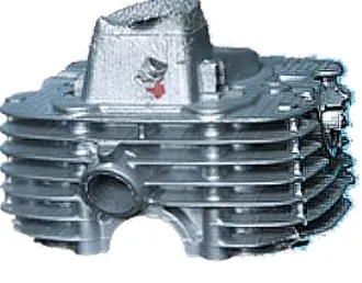
Fig 2.Cylinder Head
The force or knocking of guns is in horizontal direction only. In order to clamp the job, types of chisel play an important role. Proper clamping of the component is assured by the clamp and in return helps in efficient decoring process.
ii. Vertical Decoring Machine
In Vertical decoring machine, the castings are hammered with an air operated system (which are mounted vertically) to remove the sand. The decoring device is housed completely inside a soundproof booth equipped with sliding door for casting load/ unloads. The frame that supports the castings consists of a steel structure with specific locator (Fixture) & dampened clamping system. The decored sand is collected in the lower part of the machine in trolley. This machine is used for decoring aluminum castings like cylinder heads, engine blocks, intake manifolds etc. This is the most economic method of decoring. The force of the guns is acting ion downwards directions there by guns are
indeed placed in vertical position. It ensures self clamping of components having larger sizes. Small size components face difficulty in decoring.
Fig 3. Vertical Decoring machine
It is self clamping machine, in other words it does not require separate device in order to clamp the work pieces. It is slightly more effective than the horizontal type. Its guns are placed in vertical position facing in downward direction as we can see the above figure. It is preferred mostly for the big job sizes which cannot be fitted in horizontal type. Small work pieces can difficult to clamp in this vertical as only one gun can operate or hold on one piece.
4. Pneumatic Circuit Design
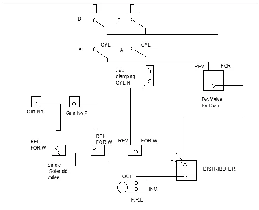
Fig 4. Pneumatic circuit
There are basically three types of chisels used in these guns. The name of this chisel is given after their geometric or cross section shape of that area which comes in contact of the work piece. They are as follows:
i. Rectangular type: The front part (that area which comes in contact of the work piece) is rectangular in shape
ii. Trapezoidal type :The cross section is in trapezoidal shape
iii. Circular type: It has circular cross section.
The company already uses trapezoidal and rectangular type of chisel in pneumatic guns. We have observed that the use of this leads to the impression on the riser portion of the work piece and also in some cases leads to breaking of it and damaging of the component. This problem was overcome by use of circular type chisel. The cross section area of the chisel is more so the stress concentration on the riser is less so no impression or breakage of riser of the component. And the advantage of cross section was that it helped in clamping of device. So as we can see in the above figure the vertical clamp is removed as there was no need of it after the use circular cross sectional chisel. The above diagram shows the design of pneumatic system used in decoring machine. Following are the parts used in above system:
i. Double Acting Cylinder:
A double-acting cylinder is a cylinder in which the working fluid acts alternately on both sides of the piston. In order to connect the piston in a double-acting cylinder to an external mechanism, such as a crankshaft, a hole must be provided in one end of the cylinder for the piston rod and this is fitted with a gland or 'stuffing box' to prevent escape of the working fluid. Double-acting cylinders are common in steam engines but unusual in other engine types. Many hydraulic and pneumatic cylinders use them where it is needed to produce a force in both directions. A double-acting hydraulic cylinder has a port at each end, supplied with hydraulic fluid for both the retraction and extension of the piston. A double-acting cylinder is used where an external
force is not available to retract the piston or where high force is required in both directions of travel.
ii. Pneumatic operated guns:
These guns are used for applying force on component and give required vibration to the component to remove the sand cores easily. It also helps in clamping of job in case of vertical decoring machine. The main purpose of it is to loosen the sand. These guns are purchased from Hydrotek Company. The weight of the gun is 5kilograms and working Pressure is 150kgs.
iii. Distributer:
It is used to distribute the air in the pneumatic system as per the requirement. It has single input and multiple output . We are using 5/2 distributer valve for the system.
iv. Air filter:
A particulate air filter is a device composed of fibrous materials which removes solid particulates such as dust, pollen, mould, and bacteria from the air. A chemical air filter consists of an absorbent or catalyst for the removal of airborne molecular contaminants such as volatile organic compounds or ozone. Air filters are used in applications where air quality is important, notably in building ventilation systems and in engines.
v. Lubricator:
A lubricator injects an aerosolized stream of OIL into an airline to provide lubrication to the internal working parts of pneumatic tools, and to other devices such as actuating valves and motors. A lubricator should always be the last element in an FRL (Filter-Regulator-Lubricator) unit. If an FRL is connected "backwards" with incoming air connected to the lubricator, oil-laden air interferes with pressure regulator operation, oil is separated from the air stream and drained by the filter, and very little or none is delivered to connected equipment.
iv. Air storage tank:
Compressed air energy storage is a way to store energy generated at one time for use at another time using compressed air. At utility scale, energy generated during periods of low energy demand (off-peak) can be released to meet higher demand (peak load) periods.Small scale systems have long been used in such applications as propulsion of mine locomotives. Large scale applications must conserve the heat energy associated with compressing air; dissipating heat lowers the energy efficiency of the storage system.
v. D.C.Valve:
5. Sequence of operation:
i. Start the air supply at an appropriate pressure (i.e. working pressure) for best results.
ii. Place casting on fixing properly. iii. Switch on switches to start machine iv. Install chisel to be used.
v. Select mode of operation i.e. auto/manual. Use manual mode for setting purpose.
vi. Press POWER ON switch.
vii. If mode of operation is manual, press JOB CLAMP switch.
viii. Guns will forward and automatically the Job will clamped(No vertical forces are acting).
ix. For AUTO MODE press both push buttons provided on the side of door, to start operation sequence.
x. Press DOOR CLOSE switch to close the door during operation.
xi. Pneumatic gun will start knocking the casting. After pressing CHISEL ON switch.
xii. After some time which is required for releasing sand from casting,press CHISEL OFF switch to stop hammering operation.\
xiii. Press DOOR OPEN switch to open door. xiv. Press JOB DECLAMP switch to declamp the job.
xv. Guns will move away from the job there by declamping it.
xvi. This completes hammering operation to release sand from casting.
xvii. Remove the job from the fixture and place new job and repeat the process.
xviii. In case machine is on AUTO mode, press push buttons to start the cycle.
xix. In AUTO mode after operation time is over reverse cycle starts automatically.
xx.
In case of any kind emergency press EMERGENCY OFF switch.6. Fixture Design
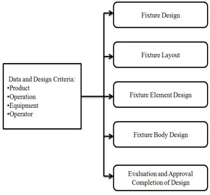
Fixture planning is to conceptualize a basic fixture configuration through analyzing all the available information regarding the material and geometry of the workpiece, operations required, processing equipment for the operations, and the operator. The following outputs are included in the fixture plan:
i. Fixture type and complexity ii. Number of workpieces per fixture iii. Orientation of workpiece within fixture iv. Locating datum faces
v. Clamping surfaces Support surfaces, if any
Generation of fixture layout is to represent the fixture concepts in a physical form. The following outputs are included in the fixture layout:
Fig 5. Flow Chart of Fixture plan
i. Zero positions of locators ii. Positions of clamps
iii. Positions of supports, if any iv. type of locators
v. Type of clamps vi. Type of supports
vii. Clamping forces and sequence
viii. Fixture element design is either to detail the design drawings committed on paper or to create the solid models in a CAD system of the practical embodiment of the conceptual locators, clamps and supports. It is possible to use standard designs or proprietary components. The following outputs are included in the fixture element design:
ix. Detailed design of locators x. Detailed design of clamps
xi. Detailed design of supports, if any
xii. Tool body design is to produce a rigid structure carrying all the individual fixture elements in their proper places
6.1 Fixture designing procedure followed:
i. The first and the most important step of our design procedure was the study of exact working of the machine. This included calculation of the forces generated by the vibrating guns on the workpiece. This helped us in deciding the dimensions of our fixture to ensure complete efficient working of the machine without damaging the fixture or the workpiece.
ii. Next step included proper dimensional study of the workpiece given to us by the company. The workpiece was a cylinder head. All its dimensions were noted for better accuracy of the fixture design. This was a very important step as it decided the dimensions of the fixture to ensure the proper positioning of the vibrating guns at the desired position. Any errors in the gun positioning would cause improper functioning of the machine.
Fig 6. Initial Concept Model
i. Next step was to prepare rough sketches of design of the fixture as per the requirements. Many options were made, and then an optimum design was selected based on the discussions with the company heads
ii. After a rough design was fixed, next step was to prepare a proper CAD model of that design. This was done using the CATIA V5 R20 software. The outer dimensions of the fixture were decided according to the constraints given by the company of the casing of the machine.
iii. After CAD model it was mandatory to check the accuracy of the design dimensions. Hence it was decided to make a wooden prototype of the design made after on the software.
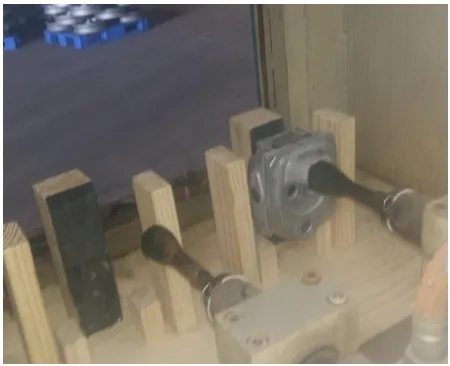
iv. After the prototype was ready, it was tested for its dimensional accuracy. It was placed inside the machine and position of guns was tested.
v. It was observed that only 1 gun had is positioned as per the requirement while other was offset from the gun as we can also see it from the above picture.
Fig 7.Testing of Prototype
vi. The prototype required future changes which were carried out and dimensional changes were made.
vii. In this design the entire blocks was made of same material as per our approach and few mm of rubber coating was planned.
viii. More slots were added for easy removal of the sand falling from the casting.
ix. Provisions were made to allow the sand to fall directly at the bottom of machine where all the sand is collected for disposal purpose.
x. Material for fixture was decided as MS (mild steel). Also, for reducing the weight of the fixture, material was removed from the side pillars.
xi. This empty region was then decided to be filled with rubber. This rubber would help to absorb vibrations and prevent damage to the casting as well as the fixture and the operator.
Fig 8. Modified Model without Hard Rubber
6.2 Final Fixture Design
We made changes which were required after testing the prototype. Inorder to confirm the design we meet the fixture expert from Laxmi Tools, Bosari, Pune. Then he guided us for future improvement in design and to reduce the weight of the fixture.Changes made were as follows:The material used for the fixture was more hard rubber than the mild steel hence it saved lot of dead weight and also the cost of fixture.
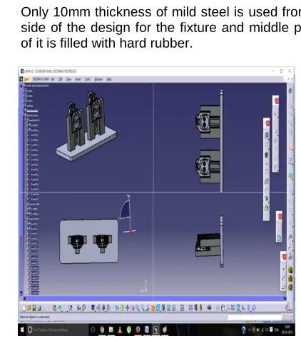
i. Only 10mm thickness of mild steel is used from any side of the design for the fixture and middle portion of it is filled with hard rubber.
Fig 10.Othographical views of fixture
ii. The extra cushion was provided of rubber so there is no direct contact of the work piece with the mild steel hence lesser chances of damage.
iii. The other problem which was taken care of was the removal of sand from the either sides of the job. iv. By lifting the fixture the arrangement was made
such that the small opening of the hole is obtain so sand comes out easily.
v. The figure above shows the close view of the opening obtain from where the sand will automatically be removed and decoring process is successfully completed.
vi. The back portion or the resting of fixture is also covered with rubber as most of the impact force will be acting on it.
vii. Some amount of space is given so that after guns impact can be sustain successfully by the fixture and no damage is cost.
Fig 11.Close view of the fixture
Fig12. Small opening for sand removal
viii. This also helps in keeping the environment clean as the sand coming out can be blown off to the trolley or sand collector which is kept under the machine by pressurized air.
6.3 Features of our fixture:
i. It is capable of decoring 2 castings in one machine cycle. This is very important toincrease the production rate, as manual decoring takes around 90 to 100 seconds for single casting, but this machine will decore 2 castings in less than 40 seconds.
ii. No need of separate clamping device. The fixture has been designed in such a way that the vibrating guns will serve as natural clamping. This has helped in reducing the cost and weight of the fixture. iii. Accurate positioning of the vibrating guns. The
dimensional accuracy of the fixture has led to perfect positioning of the guns to enhance the decoring effect.
iv. The major part of the fixture is made of hard rubber hence the fixture is light in weight.
v. Slot provisions for easy removal of the decored sand. This is very important for continuous working of machine. This reduces stoppage time for cleaning of the fixture. Thus reducing its maintenance cost. vi. Ease of placing the casting in the fixture.
vii. No complicated locating and clamping devices, hence the time taken by the operator to place the casting in the fixture is less. This also reduces the overall cycle timing.
viii. The rubber added to the fixture not only absorbs the vibration, but also helps in reducingthe noise generated by the machine. Hence, it makes the machine quieter in operating conditions.
ix. Simple design to fabricate.
x. Optimum cost uptoRs.10000 to Rs.15000/-depending upon the quality of MS and rubber used.
Conclusion
us to strong conclusion:
1. Reduction in rejection rate. 2. Time saving.
3. Cost saving.
4. Proper use of human resource.
The use of automation process lead to proper handling of the components and proper decoring process. The rejection rate is decreased from 20 rejections to 5 rejections thereby saving the cost of reworking and reprocessing. Proper automation of decoring machine gives ability to decore two components at a time which is double the rate of traditional process used in the industry (manual decoring). It reduces the time consumption to half. As the rejection rate is reduced by 15 components the process is efficient in terms of cost. Calculations for cost saving gives the payback period which is about 6 months i.e. all the investments were done for modifications of traditional decoring process is recovered in 6 months. Automation leads to effective utilization of decoring machine as it requires less labor work; which saves more labor cost for industry. This will lead to effective use of remaining human resource available in industry.
References:
[1] United States Patent, Vibratory Apparatus, Choules et al. Date of Patent: June 24, 1975
[2] United States Patent, Decoring Method, Stephan Date of Patent: Mar. 25, 1986
[3] International Patent Classification, Device for Decoring Casting Pieces CESTARO, Giorgio (IT/IT]; Date of Patent:21 September 2000
[4] Dr. Yadav alli Basavaraj, Pavan Kumar B K, Modeling and Analysis of Support Pin for Brake Spider Fixture e-ISSN: 2278-1684 Volume 6, Issue 1 (Mar.- Apr. 2013), PP 10-15
[5] Kiran Valandi, M. Vijay Kumar, Kishore Kumar S. Development, Fabrication and Analysis of Fixture Vol. 3, Issue 4, April 2014