ISSN (e): 2250-3021, ISSN (p): 2278-8719
Vol. 08, Issue 5 (May. 2018), ||VIII|| PP 59-67
Seismic Vibration Control of Multi-Storey Asymmetric Building
Riya M. Shah
1, Snehal V. Mevada
2, Darshana R. Bhatt
31(Structural Engineering Department BVM Engineering College, India)
2
(Structural Engineering Department BVM Engineering College, India) 3(Structural Engineering Department BVM Engineering College, India)
Corresponding Auther:Riya M. Shah
Abstract:
As recorded in the past, the response of structuresthat are asymmetric when subjected to earthquake have depictedthat they are excessively vulnerable to edge deformations. Theinvestigation presented here examined how the installation ofsupplemental viscous dampers and magneto-rheological dampers controlled the largely prevalent deformations in G+3 storey, one-way asymmetric buildings.Torsional and Lateral displacement for controlled anduncontrolled system were obtained along with the torsional and lateral acceleration response and it was concluded thatlinear viscous dampers are less effective than the non-linear viscous as well asmagneto-rheological dampers.Keywords: - Asymmetric, eccentricity, viscous dampers, MR dampers
--- --- Date of Submission: 11-05-2018 Date of acceptance: 28-05-2018 --- ---
Listof symbols
Symbol Explanation
a Plan dimension in x-direction
a0, a1 Rayleigh’s damping coefficients depending upon damping ratio for first and second vibration modes
A System matrix
Ad Discrete time-system matrix b Plan dimension in y-direction B Distribution matrix of control forces Bd Discrete-time matrix of control matrix c0i Viscous damping at large velocities
C1i Nonlinear roll-off in the force-velocity loops at low velocities C Damping matrix
Cd Total damping coefficient CR Centre of resistance CM Centre of mass
ex Eccentricity (distance between CR and CM) E Distribution matrix for excitation forces Ed Discrete-time matrix of excitation forces Fdy Resultant damping force in y-direction Fdθ Resultant damping force in y-direction Fdf Force in damper in flexible edge Fdi Force in damper in ith damper Fds Force in damper in stiff edge FdT Resultant damper force F Damper force vector g Gravitational acceleration I Identity matrix
K Stiffness matrix
K0 Coefficient present to check the stiffness at large velocities k1 Accumulator stiffness
kθθ Torsional stiffness about vertical axis m Limped mass of each slab
M Mass matrix
r Mass radius of gyration from CM about vertical axis T Time period of building
ui Relative displacement at ith stiffness damper üyand uy Lateral acceleration and displacement at CM
üyf and uyf Lateral acceleration and displacement at flexible edge üy and uy Lateral acceleration and displacement at stiff edge üyθ and uyθ Lateral acceleration and displacement in θ-direction u Displacement vector
u Velocity vector ü Acceleration vector ug Ground acceleration vector ugy Ground acceleration in y-direction x0 initial displacement of spring k1 xi x-coordinate relative to CM yi y-coordinate relative to CM z State vector
Γ Influence coefficient vector
ωθ Uncoupled torsional frequency
ωy uncoupled lateral frequency
Ωθ ratio of uncoupled torsional and that of lateral frequency of the system in y-direction Λ Location matrix for control forces
I.
INTRODUCTION
In recent years, due to advancement in technology, design and increased quality of materials in civil engineering have resulted in lighter and more slender structures. Due to this, the structures in earthquake or wind prone regions are subjected to higher structural vibrations causing serious structural damage and possible structural failure. Structural control itself is a very vast field of study currently and it looks assuring in attainment of lesser structural vibrations when subjected to earthquake loads and strong wind loads. The abstractions of utilizing structural control in order to reduce such vibrations in structures was suggested in the year 1970. A mechanical system is set up in structure to check and minimize these vibrations. For asymmetric buildings the control of the seismic responses are presented here. It is usually observed that symmetric structures are less affected during stronger earthquakes leading to lesser damage than symmetric building. When centre of rigidity and centre of mass are located at different points then structure is called an asymmetric structure.
Chang et al (1998)[1] proposed on how to analyse and design visco-elastic dampers in a 5 storey structure by equivalent strain energy method. Dynamic analysis was carried out where dampers were designed that had different damping ratio at different temperatures. Study was done based on experimental as well as the analytical results and based on that study, the modal strain energy technique has been incorporated into the computer programs ETABS for analysis of structure with supplemental VE Dampers. Goel (2000)[2] identified the system parameters for asymmetric structures with viscous dampers that controlled the seismic responses of the buildings. And also investigated deformations in plan wise asymmetric buildings in which he found that for linearly-elastic, single-story, asymmetric structure having added viscous dampers showed reduced edge deformations. Particularly, it was observed that the symmetric distribution of added damping led to a lesser reduction in values of edge deformations when compared to asymmetric distribution. Kim and Bang (2002)[3] developed a strategy for distribution of viscoelastic dampers for reduction of the torsional displacement as well as acceleration values for an asymmetric structure. Mevada and Jangid (2012) [4] analyzed linearly elastic one-way asymmetric and one-storey structure employed with semi-active variable dampers and investigated it under various actual earthquake motions. The responses were investigated considering the force algorithm of two-step viscous damping to carry out the study the effectivity of the semi-active damper system and the effect resulting due to torsional coupling.
II.
STRUCTURAL MODEL AND GOVERNING EQUATIONS OF MOTION
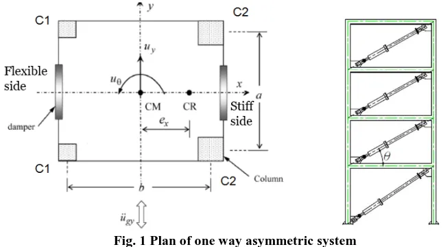
The system considered is an ideal G+3 structure consisting of columns supporting a rigid slab as stated in the Figure 1. Assumptions that were made for given system are as stated below: (i) slab of the structure is rigid, (ii) force-deformation pattern for the given structure is assumed of being linearly elastic and also (iii) the considered building is excited upon the action of horizontal component of earthquake excitation in single direction. The slab having uniformly distributed mass and so the geometric centre coincides with the structure’s centre of mass (CM). The stiffness asymmetry with respect to the CM in only one direction is generated because of the specific arrangement of columns as shown in Figure 1, so in x-direction, there is an eccentric distance, ex between the Centre of stiffness (CR) and CM. The structure has symmetry in x-direction and so, two degrees-of freedom are taken into consideration for model that is the torsional displacement, uθ and the lateral displacement in y-direction, uy as shown in Figure 1. The equation for motion are obtained as
Mü + Cu̇ + Ku = -MΓüg + ΛFd (1)
𝑀 = 𝑚 0
0 𝑚𝑟2 (2)
Where, 𝑟 = 𝑎2+ 𝑏2/12 is about vertical axis.Based on Goel, 1998, stiffness matrix for the given structure is changed as follows,
𝐾 = 𝑘𝑦
1 𝑒𝑥
𝑒𝑥 𝑒𝑥2+ 𝑟2𝛺𝜃2 (3)
𝜔𝜃 = 𝐾𝜃𝑟
𝑚 𝑟2 and 𝜔𝑦=
𝐾𝑦
𝑚 (4)
𝑒𝑥= 1
𝐾𝑦 𝐾𝑖 𝑦𝑖𝑥𝑖 and 𝛺𝜃 = 𝜔𝜃
𝜔𝑦 (5)
𝐾𝜃𝑟 = 𝐾𝜃𝜃 − 𝑒𝑥2𝐾𝑦 and 𝐾𝜃𝜃 = 𝐾𝑖 𝑦𝑖𝑥𝑖2+ 𝐾𝑖 𝑥𝑖𝑦𝑖2 (6)
The damping matrix for the structure is not known in definite manner but is obtained by considering Rayleigh’s proportionality as,
𝐶𝑑 = 𝑎0𝑀 + 𝑎1𝐾 (7)
Fig. 1 Plan of one way asymmetric system
For study taken here, both modes of structural vibrations is assumed to be taking 10% damping. The equation for motion are solved by considering the state space method (Hart and Wong, 2000) as,
ż= 𝐴𝑧 + 𝐵𝐹 + 𝐸ü𝑔 (8)
Where, state vector is z = {u u̇}T ;
𝐴 = 0 𝐼
−𝑀−1𝐾 −𝑀−1𝐶 ; 𝐵 =
0
−𝑀−1 𝛬 𝑎𝑛𝑑𝐸=
0
𝛤 (9)
Where, Control forces are taken as constant within any given time intervals, and the solution can be stated in incremental pattern (Hart and Wong, 2000),
𝑧 𝑘 + 1 = 𝐴𝑑𝑧 𝑘 + 𝐵𝑑𝐹 𝑘 + 𝐸𝑑ü𝑔{𝑘} (10)
𝐵𝑑 = 𝐴−1 𝐴𝑑− 𝐼 𝐵𝑎𝑛𝑑𝐸𝑑 = 𝐴−1(𝐴𝑑− 𝐼)𝐸 (11)
III.
MODEL OF FLUID VISCOUS DAMPER
Viscous dampers operate on the principle of fluid flowing through orifice and provide resisting forces based on the structural motion when subjected to earthquake induced dynamic forces. Figure 2 shows a mathematical and schematical model of viscous damper. An emblematic viscous damper has a cylindrical body which contains central piston within a fluid chamber. The pressure difference generated across the piston assembly which is connected between two ends of building results in damper force. Figure 2 shows the model of viscous damper which is demonstrated by Symans and Constantinou (1998) and Lee-Taylor (2001).
Fig. 2 Mathematical and Schematic model for viscous damper
The force in damper is directly proportional with the relative velocity between the ends of viscous damper as shown in following equation,
Fd= Cd z d αsgn(z d) (12)
Where, for any ith damper, α is the damper exponent ranging from 0.2 to 1 for seismic application (Soong and Dargush, 1997) and sgn(·) is signum function. The piston head orifices primarily controls the exponent value. When α = 1, it is known as a linear viscous damper (LVD) and for α smaller than 1, given damper is considered as a nonlinear viscous damper (NLVD) which in this case is taken as α = 0.5 for NLVD. Dampers having α greater than 1 have not been used much practically.
IV.
MODEL OFMAGNETORHEOLOGICAL DAMPER
Magnetorheological (MR) dampers are semi-active systems using MR fluids to cater control forces that are fairly promising in civil engineering uses. During malfunctioning of hardware they offer highly dependable operation at a bare minimum cost and they behave as a passive damper and hence are considered fail-safe. MR fluids contains micro-sized particles that are polarizable when kept in vicinity of magnetic force. These particles are dispersed withn a special medium like oil of silicon. Whenfluid is acted upon by magnetic field, chains of particlesformrendering the fluid to be semisolid in state, showing plastic behavior. These fluid has large yield strength, lower viscosity and stable hysteretic behaviour over a wide temperature range. It just takes milliseconds for such devices to transit to rheological stability stage furnishing high band-width to devices. As a result of such mechanism higher forces can be generated.
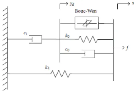
Presently, the Modified Bouc-Wen model specified by Spencer et al. as shown in Figure 3 is used. Over a wide range of inputs this model accurately predicted the behaviour of prototype MR damper. The equations governing the force predicted by this model is
fi = αizi+ c0i x di− y di + k0 xdi− ydi + k1 xdi− x0
= c0iy di+ k1(xdi− ydi)
(13)
Where, variable ziis given as
z i= −γ x di− y di zi zin−1− βm(x di− y di) zi n+Am(x di− y di)
y di =
1 (c0i+ c1i)
αizi+ c0ix di+ k0 xdi− ydi
(14)
To account for the dependence of the force on the voltage applied to the current driver and the resulting magnetic current, the suggested parameters are
αi= αa+ αbudi , c0i= c0a+ c0budi , c1i= c1a+ c1budi (15)
V.
NUMERICAL STUDY
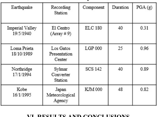
Seismic response values of G+3, one-way asymmetric and linearly elastic building is investigated for different actual earthquake ground excitations by studying the numerical simulation. The response values considered are lateral as well as torsional displacements of deck mass at the CM and edges. (uy, uθ, uys and uyf respectively); also lateral and torsional acceleration for deck mass at the CM and edges (üy, üθ, üys and üyf respectively) and forces in dampers employed at stiff and flexible edge of structure (Fds, Fdf respectively) along with the resultant damper force, Fdy (= Fds + Fdf). The response values for the given system is carried under the following parametric variations: lateral time period of the system (Ty = 2π/ωy), Ωθ = ωθ/ωy i.e. the ratio of uncoupled torsional to lateral frequency. The dampers employed are LVDs, NLVDs and MR dampers. The peak responses are taken corresponding to parameters listed above for four considering earthquake excitations namely, Loma Prieta (1989), Imperial Valley (1940), Kobe (1995), Northridge (1994) having 0.96 g, 0.31 g, 0.82 g and 0.89 g as peak ground acceleration (PGA) values; details summarized as in Table 1. For the study, the aspect ratio is kept as unity for the given plan dimension. Also, total two dampers placing one at each edge are employed in the structure.
Table 1 Details of earthquake excitations
VI.
RESULTS AND CONCLUSIONS
Fig. 5 Hysteresis loop for Imperial Valley earthquake
Table 2: Responses under Imperial Valley Earthquake
Response parameter Uncont rolled Controlled with LVD % reducti on Controlled with NLVD % reducti on Controlled with MRD % reducti on DISPLACEMENT (m) 0.14 0.07 48.81 0.08 42.06 0.12 14.16 ACCELERATION
(m/s2) 0.01 0.01 55.87 0.01 49.21 0.09 -551.3 TORSIONAL
DISPLACEMENT (rad) 5.68 3.20 43.60 5.57 2.00 6.72 -18.22 TORSIONAL
ACCELERATION
(rad/s2) 1.05 0.63 39.47 1.11 -5.62 1.52 -45.24
Table 3: Responses under Kobe Earthquake
Response parameter Uncont rolled Controlled with LVD % reducti on Controlled with NLVD % reducti on Controlled with MRD % reducti on DISPLACEMENT (m) 0.41 0.34 18.21 0.36 11.84 0.75 -83.00 ACCELERATION
(m/s2) 0.05 0.03 27.94 0.04 24.69 0.50 -948.0 TORSIONAL
DISPLACEMENT (rad) 18.83 13.74 27.03 16.54 12.19 37.51 -99.18 TORSIONAL
ACCELERATION
(rad/s2) 3.51 2.53 28.04 3.08 12.26 6.44 -83.34
Table 4: Responses under Loma-prieta Earthquake
Response parameter Uncont rolled
Controlle d with LVD % reducti on Controlled with NLVD % reducti on Controlled with MRD % reducti on DISPLACEMENT
(m) 0.28 0.21 25.78 0.22 19.63 0.27 4.83 ACCELERATION
(m/s2) 0.03 0.02 28.00 0.02 21.49 0.20
-606.15 TORSIONAL
DISPLACEMENT
(rad) 12.63 8.36 33.82 9.77 22.61 13.57 -7.46 TORSIONAL
ACCELERATION
(rad/s2) 2.26 1.43 36.65 1.70 24.67 2.16 4.40
Table 5: Responses under North-ridge Earthquake
Response parameter Uncont rolled
Controlle d with LVD % reducti on Controlled with NLVD % reducti on Controlled with MRD % reducti on DISPLACEMENT (m) 0.41 0.34 17.07 0.36 12.34 0.46 -11.61 ACCELERATION
(m/s2) 0.04 0.03 29.51 0.03 22.25 0.31
-677.42 TORSIONAL
DISPLACEMENT
(rad) 16.49 14.21 13.79 15.10 8.40 21.79 -32.16 TORSIONAL
ACCELERATION
(rad/s2) 2.15 1.56 27.42 1.67 22.31 2.63 -22.13
VII.
DISCUSSIONAND CONCLUSION
displacement and acceleration values. Also it was obtained that NLVDs are more effective than LVDs and MR damper in this case. The MR dampersemployed here have reduced the values to some extent for some cases however the capacity of MR dampers used here in 200kN on increasing which more reductions can be obtained.
REFERENCES
[1] K.C. Chang, Y.Y. Lin, M.L.Lai, “Seismic analysis and design of structures with visco-elastic dampers", Proceedings, ISET Journal of Earthquake Technology, vol. 35, pp.143-166, December 1998, p. 380, No.4.
[2] Goel R. K. “Passive control of earthquake induced vibrations in asymmetric buildings",12WCEE 2000. [3] Jinkoo Kim ,Sunghyuk Bang, “Optimum distribution of added visco-elastic dampers for mitigation of
torsional responses of plan-wise asymmetric structures",Engineering Structures vol. 24, 2002,1257-1269. [4] Mevada Snehal, Jangid R S, ” Seismic response of torsionally coupled System with semi-active variable
dampers”, Journal Of Earthquake Engineering, 2012,16:7, 1043-1054.
[5] Goel R K,“Effects of supplemental viscous damping on seismic response ofasymmetric-plan systems”, Earthquake Engineering and Structure Dynamics, 1998,vol 27 No. 2, 25–141.
[6] Lee D, Taylor DP, “Viscous damper development and future trends”, Structure Design of Tall Buildings,2001, vol 10 No. 5, 311–320.
[7] Symans MD, Constantinou MC, “Passive fluid viscous damping systems forseismic energy dissipation” ISET Journal of Earthquake Technology,1998, vol 35 No. 4, 185–206.
[8] A. K. Chopra, Dynamics of structures, theory and appliction to earthquake engineering. Pearson education, Inc., 2007.
[9] Gary C Hart, Kevin Wong, Structural Dynamics for Structural Engineers. John Wiley And Sons inc.,2000.
[10] Soong TT, Dargush GF, “Passive Energy Dissipation Systems in StructuralEngineering”,1997, John Wiley & Sons, Inc., New York.