Real-Time Pen Input System for Writing Utilizing Stereo
Vision
Fadi Imad
1*, Sharifah Mumtazah Syed Ahmad
1, Shaiful Hashim
1, Khairulmizam Samsudin
1,
Marwan Ali
21 Department of Computer and Communication Systems Engineering, Faulty of Engineering, Universiti Putra Malaysia, Serdang, Malaysia.
2 School of Engineering, RMIT University, Melbourne, Vic, 3083, Australia.
* Corresponding author. Tel.: +60183212799; email: [email protected] Manuscript submitted December 20, 2017; accepted February 15, 2018.
doi: 10.17706/jcp.13.9 1000-1009.
Abstract: A system that captures handwritten words on a piece of paper utilizing two cameras which observe and track a pen’s tip lateral movement is presented. The system tracks the pen’s tip in real-time based on the two images vision using colored markers. The stereo camera is calibrated for accurate three-dimensional (3D) positioning of the pen’s tip. Pen’s tip 3D coordinates are then being used to re-construct the handwritten input into computer image. Experimental results show that the system can detect and track handwriting within 1mm accuracy on the y-axis and 7 mm accuracy on the x-axis (depth).
Key words: Stereo vision, real-time vision, 3D tracking, pen-based interface.
1.
Introduction
Traditional user interface methods with computers such as knobs, sliders, keyboards and mice have been the most common for many tasks. However, in some tasks such as drawing and writing those methods are not user friendly. The industry has recognized the shortcomings of traditional user machine interface methods in such tasks compared to the convenience of pen-based interface. Therefore, digitizing tablets and screens were introduced since the early 1990s. Since the input device is the computer screen or a tablet and they must be large for convenience of use and because digitizing sensors are embedded on the surface. Their large size makes them bulky and not applicable to hand held devices of nowadays.
With the exponential increase of performance of technology over time. The CPU processing power has seen a 1 trillion-fold increase over the past 60 years [1]. This increase in processing power of CPU along with the increase in cameras resolution and the slump in their prices all make cameras a feasible choice as sensors. Handwriting or drawing can be captured in real-time using video cameras instead of using the conventional tablets and touchscreens. This alternative is much more user friendly because of the freedom and the flexibility of the interface system. It also allows users to write more intuitively. Furthermore, the writing area is not limited by the physical size of the digitizer in the conventional tablet, surface or similar system [2], [3].
output as a good quality image which can be used for character recognition if required. The interface system consists of two video cameras, a pen with two colored markers, one just above the tip of the pen and one at the other end. The two cameras are to be placed on the writing surface focusing of the pen. Image processing algorithm allows for the tracking of the pen’s tip position and pen’s tilting angle in each video image frame. Then stereo imaging techniques are used to find the 3D position of the pen’s tip and pen’s tilting angle.
The paper is organized as follow: In Section 2 a summary of previous similar or related work is done. Then in Section 3 the design of the system is described. After that, Section 4 presents how the system performance was evaluated and the number of experiments. Finally, the concluding findings and observations as well as future research directions are presented in Section 5.
2.
Related Work
The research work on handwriting or drawing detection mainly takes two pathways either offline or real-time. The offline systems detect the written text from a static image which is taken after the writing. The most popular for offline is the optical scanner. Alternatively, real-time systems perceive the written text from analyzing the pen’s tip movement in a live video feed. Real-time systems are the cutting edge because they allow for immediate display of handwriting. The most common example of these real-time capturing systems are the electronic tablets, for example Wacom’s tablet [4].
Research attempts which aim to provide a user-friendly input solution for handwriting and drawing that do not rely on sensor tablet started since the early 80s. In 1984 K.Sato et al. [5] developed a way for extracting online stroke data from input patterns using a CCD camera. They have tried to obtain the pen tip position and pen up-down on the writing plane using its shape and shadows. Then in 1996 Toshinori Yamasaki et al. [6] improved on the system through extracting the stroke data from the sequential input pattern. However, the one of main drawbacks of this technique is the inclusion of undesirable patterns such as the writing pen, the hand and the shades. They have suggested taking the image from the reverse side of the writing plane to overcome the drawback.
Another system was implemented by H.Bunke et al. [7] for real-time handwriting acquisition by reconstructing the movement of the pen tip from a sequence of images. The distinction between pen-up and pen-down strokes is accomplished using nearest neighbor classifier. The method applied faced two major problems which are the movement of hand, pen and shadows which are perceived as handwriting. The second problem is the occluded ink traces by pen or hand. They have overcome these problems by using the last frame to extract the text which defies the main purpose of the system being real-time. Likewise Gernot A.Fink et al. [8] improved on previous works by utilizing pre-processing and pen-up/down classification. Pen tracking was accomplished using a combination of template matching for the pen’s tip and motion prediction using Kalman filter. While the challenge of pen-up/down stroke distinction was solved by searching for ink traces in the vicinity of pen trajectory. To overcome the occlusion by the pen tip or writer hand, pen-up/down classification is performed with a time delay of 1 second. However, this induced some latency to the operation of the system. Other similar work has followed by Mario E. Munich et al. [9] where they have worked on saving computational requirements. This was performed through designing a filter which predicts the most likely position of the pen tip on the next frame reducing the search area. Other researchers have worked on improving the reliability of pen up/down classification as it is one of the main challenges for pen tracking.
power. Therefore, Makoto Mariya et al. [10] in 2005 developed a video tablet system based on stereo cameras. They were able to detect the tip position in the image frames using colored markers. The system inferred the depth information from the parallax between the tip in the two frames. However, the placement of the camera directly above the writing plane hindered the writing process by blocking the users view.
The advancements in the depth sensors technology for examples Kinect® and the leap motion sensors can solve the problem of tracking the tip position and up/down classification. However, the fundamental technology these sensors rely on has some drawbacks. These systems use infrared source along with infrared camera to map the surrounding. The downside of using infrared that these systems cannot operate under the interference of sunlight or other infrared sources.
3.
System Description
Fig. 1. Experimental setup.
The proposed system for video based real-time writing tablet consists of three main components as shown in Fig. 1. Firstly, for detecting pen from the video frames, the pen has two color markers made with non-glossy colored tape to avoid light reflection which can change the color contrast. The green color was purposely chosen in order to avoid interference because green objects are rarely used indoors [11]. For outdoors applications, different colors maybe used to avoid interference.
Fig. 2. Stereo camera configuration.
3.1.
Pen Tip Tracking Algorithm
The image sequences used for pen tracking are captured in an image resolution of 640 × 480 pixels. Each camera captures 30 video frames per second. The cameras are positioned on the mount with 10 cm distance between their centers. The writing space visible by the cameras is maximized by pointing the cameras lenses in a direction parallel to the writing surface.
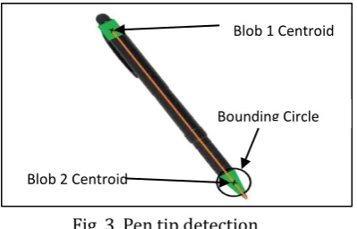
Fig. 3. Pen tip detection.
The method applied to track the pen tip position in the image frames relies on colored markers. Green colored tape is used to create two markers on the pen. One marker is near the tip to help locate the tip in the frame whilethe second is on the other end of the pen to help detect the direction the tip is pointing and if required the tilt angle of the pen. After the image was captured HSV filtering was used to extract the markers from the rest of the image. Then erosion function was applied to eliminate any green objects below the required size threshold and dilation function was applied to fill small holes in the foreground to form blobs. After that the centroid of the two blobs was detected and a bounding circle was drawn around the blob near the pen tip. Finally, a line was drawn from the centroid of the blob at the end of the pen passing through the centroid near the tip of the pen until it crosses the bounding circle. The position of the tip was at a small distance from the crossing point which can be observed in Fig. 3.
3.2.
Stereo Camera Calibration
To make use of the pen tip position in the two frames in finding the 3D location of the pen tip, the cameras has to be calibrated. The calibration process is performed to compute the extrinsic and intrinsic parameters of the camera. The extrinsic parameters of a camera specify the position and the orientation of the camera with respect to the coordinate system, while the intrinsic parameters describe the inherent properties of the camera optics, including the focal length, the image center, the image scaling factor and the lens distortion coefficients. Finding the intrinsic parameters does not pose a challenge as they represent the characteristics of the camera and do not depend on the scene viewed and, once estimated, can be re-used as long as the focal length is fixed. On the other hand, finding the extrinsic parameters which are typically, 12 rotation and translation parameters for the camera is a complex process which has to be repeated
whenever the cameras are moved or rotated. The intrinsic and extrinsic parameters can be expressed as 𝑢 and 𝑣 represent the point projection in pixels, X, Y and Z are known as world homogeneous coordinates
Blob 2 Centroid
Bounding Circle Blob 1 Centroid
𝐶ℎ =K [R│T] 𝑊ℎ
𝑢 𝑣 1
=
𝛼𝑥 0 𝑢0
0 𝛼𝑦 𝑣0
0 0 1
𝑟11 𝑟12 𝑟13 𝑡1
𝑟21 𝑟22 𝑟23 𝑡2
𝑟31 𝑟32 𝑟33 𝑡3
𝑋 𝑌 𝑍 1
[12]. While K and [R│T] symbolize the intrinsic and extrinsic parameters respectively. (𝑢0, 𝑣0) is a principal
point which represents the center of the image and 𝛼𝑥, 𝛼𝑦 are focal lengths expressed in pixel-related units.
𝑟𝑛𝑛 are the rotation parameters while 𝑡𝑛 represents the translation parameters. Finding the rotation and
translation matrices is a simple linear problem but the lens distortion complicates the problem by introducing nonlinearity. Our calibration methods used the rectangular checkerboard patterns (Tsai grid [13]) shown in Fig. 4 above, while depending on Zhang’s Camera Calibration algorithm [14].
Fig. 4. Checkerboard used for stereo camera calibration.
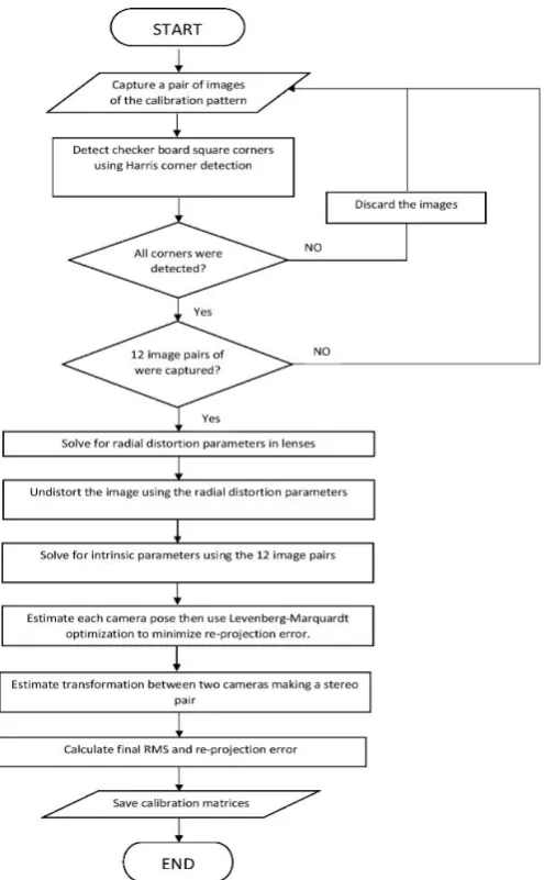
Fig. 5. Flowchart of the calibration procedure.
for detection and processing. The images are captured with the planar pattern in few different orientations to improve the accuracy of the calibration. Using edge detection and knowing the dimensions of the checkerboard squares the calibration parameters were found. A radial model is formed of the distortion coefficients and isapplied in later stages to correct geometric lens distortions. The 3D projection matrix is constructed to be used in finding the 3D position from a 2D images.
3.3.
3D World Coordinates Mapping and Translation
To track 3D world coordinates of the pen tip the video frames need to be processed in real time. The initial step was using the radial model to remove the distortion in the two frames. Then the frames were rectified making use of the translation and rotation matrices in order for them to have a common plane. After the rectification, the pen tip tracing algorithm was applied to the two frames. Following that the position of the pen in 2D was found from the position on the pen tip on the frames. Finally using the disparity which is the difference in coordinates between pen tip positions in the two frame the third dimension (depth) was found.
3.4.
Pen’s Tip 3D Coordinates to Writing
Having the 3D coordinates of the pen’s tip the written text on a plane could be simply interpreted. The 2D on the writing plane indicated the pen’s tip position on the surface of the paper. Writing traces are placed on the position if the tip is down on the paper surface. The third dimension is used to detect the pen tip up/down position. If the vertical position is below a certain threshold the pen tip was considered to be down on the pageand a trace of black pixel is plotted accordingly. The process is repeated for a sequence of frames in real-time to produce annotation, writing and drawing.
4.
Testing and Evaluation
Before evaluating the accuracy of the developed system, the calibration results were compared to actual geometric measurements of the system. Since the evaluation results are highly dependent on the system setup, the achieved results are only valid for the same camera configurations.
4.1.
Calibration
Results
Extrinsic Parameters:
R= 0 99 0 19 10
3 2 53 10 3
0 32 10 3 0 98 5 13 10 2
2 53 10 3 5 13 10 2 0 99
T=
9 93 8 38 10 2
0 49 Intrinsic Parameters: DL= [ 0 13 0 17 0 0 0 0 0 5 17 10 2]
DR= [ 0 17 0 46 0 0 0 0 0 0 29]
The distortion coefficients matrices for the left and right cameras DL and DR indicated that there is a difference in distortion due to manufacturing tolerances for the lenses.
4.2.
System Testing
In order to test the performance of the system, pen marks with known distances were placed on a piece of paper. Then the distances obtained from the stereo cameras are compared as shown in Table 1.
Table 1. Experimental Results of Actual Measurements and Measurements Obtained from the Stereo Camera
Measured Distance (mm)
Camera Obtained Distance (mm)
Error (mm)
Distance to Stereo Pair (mm)
x
(Dep
th
) 57 56 1 308
57 58 1 325
79 83 4 403
113 120 7 636
y
92 93 1 301
104 102 2 335
88 87 1 422
83 82 1 630
The data collected in Table 1 indicated that the accuracy of y-axis on the paper plane determined by the stereo pair is accurate to the range of about 1 mm. However, the error in x-axis on the paper plane which is the depth can be as large as 7 mm depending on the distance of the point to the stereo pair.
Following the initial test, the handwriting input of user on the paper was compared with the computer constructed input. A total of 15 words were written and collected to be visually inspected.
The performance of the system for the word is shown in Fig. 6. In the top, the grayscale image of the hand written complete word is shown and bellow it is the constructed word using stereo cameras.
Generally, the performance of the system is satisfactory except in the cases where the there is no enough lighting. In low lighting conditions, the pen tip detection tracking does not operate accurately due to the shift in the contrast of the colored markers used in tip detection.
Fig. 6. Handwritten words and words constructed by stereo camera.
camera were cropped then overlaid on each other as shown in Fig. 7.
Fig. 7. Handwritten words overlaid on the words constructed by stereo camera.
By visualizing the overlays, it can be noticed that the handwriting trace mostly lies within the one constructed by the stereo camera. However, there is an error margin of one pixel due to the pen tip tracking being affected by the light flickering. Although the 50 Hz anti-flickering frequency has contributed noticeably in reducing the effect of fluorescent lamps, however, flickering it still present. Since the system translates every 1 mm into a single pixel hence the system accuracy is limited to one millimeter.
5.
Conclusion
Motivated to find a more user-friendly computer input interface a stereo camera handwriting computer input system which can capture pen’s annotations in real-time. From the sequence of image frames, the 3D location of the pen tip was obtained. The 3D location of the tip in the z axis is used to in pen-up/down decision making while x and y decide the pen stroke position.
The experimentation evaluation has proven the system has an accuracy of 1mm. The accuracy of the system can also be enhanced by increasing the horizontal displacement between the two cameras. Nevertheless, this will move the common area of the cameras further away.
Few future improvements can be introduced to the system in three main areas, pen tracking method, tracking accuracy and writing smoothness. A more robust tracking algorithm such as SIFT or SURF that doesn’t require a marker can be used to track the pen tip [15], [16]. Moreover, the tracking accuracy can be enhanced by utilizing the full HD resolution of the cameras. However, these two improvements will be at the expense of frame rate unless the processing power of the computer is considerably increased. To get around this Graphics Processing Unit (GPU) is to be used to improve the throughput by processing in parallel.
Improving tracking accuracy and speed can improve the writing representation been displayed. However, to achieve a smooth representation some processing must be done to produce equally spaced intermediate points between the sparse pointes tracked by the cameras. This can be accomplished by fitting a Cubic spline to each segment then resample the spline to the desired rate [17]. A further step to enhance the system will be through implementing real-time character and word recognition of the handwritten text utilizing techniques such as Hidden Markov Model, which was proved to have a good recognition performance [18], [19].
References
[1] Moore, G. E. (2006). Cramming more components onto integrated circuits, reprinted from electronics. IEEE Solid-State Circuits Society Newsletter, 11(5), 33–35.
660.
[3] Maruyama, K., & Yamakose, H. (2008). Imaging apparatus. US Patent App, 12/118, 300.
[4] Liu, C., & Liu, C. (2010). Tablet of battery-free wireless pointing device,US Patent App. 12/457, 997.
[5] Sato, Κ., & Inokuchi, S. (1984). Video tablet-2D coordinate input device with CCD camera, Trans. IEICE Japan, J67-D(6), 726-727.
[6] Yamasaki, T., & Hattori, T. (1996). A new data tablet system for handwriting characters and drawing based on the image processing. Proceedings of IEEE International Conference on Systems (pp. 428-431).
[7] Bunke, H., Von Siebenthal, T., Yamasaki, T., & Schenkel, M. (1999). Online handwriting data acquisition using a video camera. Document Analysis and Recognitio, ICDAR '99, 573-576.
[8] Fink, G. A., Wienecke, M., & Sagerer, G. (2001). Video-based on-line handwriting recognition. Proceedings of Sixth International Conference on Document Analysis and Recognition, Seattle, WA (pp. 226-230).
[9] Munich, M. E., & Perona, P. (2002). Visual input for pen-based computers. IEEE Transactions on Pattern Analysis and Machine Intelligence, 24(3), 313-328.
[10] Moriya, M., Hayashi, T., Tominaga, H., & Yamasaki, T. (2005). Video tablet based on stereo camera — Human-friendly handwritten capturing system for educational use. Proceedings of Fifth IEEE International Conference on Advanced Learning Technologies (ICALT'05) (pp. 909-911).
[11] Aksoy, Y., Aydin, T., Pollefeys, M., & Smolic, A. (2016). Interactive high-quality green-screen keying via color unmixing. ACM Transactions on Graphics (TOG).
[12] Jain, R., Kasturi, R., & Schunck, B. G. (1995). Machine Vision, McGraw-Hill, Inc.
[13] Tsai, R. Y. (1986). An efficient and accurate camera calibration technique for 3D machine vision.
Proceedings of IEEE Conference on Computer Vision and Pattern Recognition, Miami Beach, FL (pp. 364-374). [14] Zhang, Z.. (2000). A flexible new technique for camera calibration. IEEE Transactions on Pattern Analysis
and Machine Intelligence, 22(11), 1330–1334.
[15] Lowe, D. (2004). Distinctive image features from scale invariant key points. International Journal of Computer Vision, 60(2), 91-110.
[16] Bay, H., Ess, A., Tuytelaars, T., & Van Gool, L. (2008). SURF: Speeded up robust features. Computer Vision and Image Understanding (CVIU), 110(3), 346-359.
[17] Wu, W. C., Wang, T. H., & Chiu, C. T. (2015). Edge curve scaling and smoothing with cubic spline interpolation for image up-scaling. Journal of Signal Processing Systems, 78(1), 95–113.
[18] Chen, M., AlRegib, G., & Juang, B. H. (2016). Air-writing recognition — Part I: Modeling and recognition of characters, words, and connecting motions. IEEE Transactions on Human-Machine Systems, 46(3), 403-413. [19] Chen, M., AlRegib, G., & Juang, B. H. (2016). Air-writing recognition — Part II: Detection and recognition of
writing activity in continuous stream of motion data. IEEE Transactions on Human-Machine Systems, 46(3),
436-444.
Fadi Imad was born in 1987. He received his M.Sc in electrical engineering from Universiti Tenaga Nasional in 2013 and a B.Sc degree in electrical & electronics engineering from the same university in 2010. Currently, he is pursuing his Ph.D on control systems engineering at Universiti Putra Malaysia. His research interest include artificial intelligence, robotics, machine vision and control.
Abdul Razak until 2006. Then she joined Universiti Tenaga Nasional as a senior lecturer and the head of Department of Systems & Networking until 2011. Her research interest include biometrics, security, image processing, signal processing, machine learning and steganography.
Shaiful Hashim is currently an associate professor in the Department of Computer and Communication Systems Engineering, Faculty of Engineering, Universiti Putra Malaysia. He received his Ph.D from Cardiff University, UK (2011), M.Sc from National University of Malaysia (2003) and B.Eng from University of Birmingham, UK (1998) in the field of electrical and electronics engineering. Parts of his Ph.D works have been incorporated into commercial wireless measurement system. His research interests are cloud computing, Internet of Things (IoT), network security and non-linear wireless measurement system. He has published more than fifty research publications.
Khairulmizam Samsudin is currently a senior lecturer at Computer & Communication Systems Engineering Department of Universiti Putra Malaysia. He received his Ph.D from the University of Glasgow, UK in 2002 and received his B.Sc degree in computer system and communications from Universiti Putra Malaysia in 1998. His research interests include device modelling, embedded systems, robotics, security, web services and distributed computing.