“Methodology for Analysis and Design of Leather
Groove Cutter Machine for Double Roller
Ginning Machine
Mr. Kushal J. Bahadure Dr. C. C. Handa
MCA Student MCA Student
Department of Mechanical Engineering Department of Mechanical Engineering
K.D.K.C.E. Nagpur, India K.D.K.C.E. Nagpur, India
Abstract
This paper presents the methodology for Analysis and Design for leather groove cutter machine for double roller ginning machine to designing new machine for ginning industry.The main objectives of the designing to reduced grooving time and increase productivity. The paper aims to complete fabrication of leather groove cutting machine for double roller ginning machine which consist the leather roller and grinding cutter .In first stage of designing area of maximum stress was identified related to the accuracy.
Keywords: Ginning Machine, Cotton, Leather Roller
________________________________________________________________________________________________________
I.
I
NTRODUCTIONstudy suggest that it required near about half hour to cut groove on the leather roller and after every 60 hours ,the groove made by the grinding cutter are not approximate and spherical and the depth and width of the groove increases which required 2 mm both.
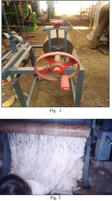
Fig. 1
Fig. 2
Due to all this problem we are able to design the leather roller groove cutter machine this is an proto type model.in which the leather roller is attatched on the main base frame stand and grinding cutter is mounted on the rack and pinion arrangement which slides as the roller rotates with the help of motor and pulley arrangement,
The leather roller rpm is maintain at 1 rpm and the grinding cutter slides along the length of the groove which is more than the length of the leather roller.as the roller rotates the the grinding cutter automatically rotates with the leather roller and the cutter rotates at 11000rpm which maintain the depth and width of the groove of roller of 2 mm.All the calculation are based on time minimum 10 to 15 sec are required to cut 1 groove on the base on roller length and no of grooves to cut. on the based of previous paper we are able to cut groove and recent industries study help us for calculating and maintaining accuracy for the leather roller.
II.
L
ITERATURE REVIEWValentin Appenzeller, Kempen present paper on”method of making helically grooved roller” In a grooved drum with a working drum surface of metal consisting of a cylindrical inner drum on which at least one ribbon is helically wound, turn by turn, the radially outer boundary of which forms the working drum surface, the ribbon also forming axially extending circumferential grooves, adjacent turns of the ribbon are connected to each other in a form locking manner on their sides facing each other in the axial direction causing the adjoining turns to be immovably xed relative to each other so that in the event of a break in the ribbon the turns will not give in to the circumferential tension force generated during winding and burst open.
cylindrical shapes. A more speci?c object is to provide an improved rolling method for the purpose indicated in which each of the several grooves is progressively formed by the repetitive rolling engagement of a forming roller or succession of like rollers therewith. Another object is to provide a gear forming method in which the gear teeth are formed by a metal rolling action that progresses across the face of the gear or substantially lengthwise of the axis thereof. Other more speci?c objects and advantages will appear, expressed or implied, from the following description of a metal rolling method performed in accordance with this invention. For purposes of illustration and explanation the method of the present invention is shown applied to the rolling of spur and helical gears, although it may be utilized to advantage in the rolling of splines and other shapes of the kind hereinabove mentioned. In the accompanying drawings: Figure l is a sectional view of gear rolling equipment capable of use in carrying out the method of the present invention.
III.
O
BJECTIVEThe main aim of this project is to overcome the traditional method
1) To design the leather roller groove cutter machine for double roller ginning machine . 2) Fabrication of leather roller using mechanical process and engg parameters.
3) To sort-out the reasons of failure of leather roller groove . 4) To suggest the solutions on failure.
IV.
R
ESEARCH METHODOLOGYThe research methodology will cover follow, sufficient literature is available related to ginning machine and leather roller. Initially the available literature would be reviewed for identifying the parameters responsible for the failure of the leather roller groove .
First the design and fabrication of leather roller groove cutter will be done using CATIA software and then analysis will give the exact location from which the leather roller groove fails. And then redesign and analysis of redesign leather roller groove cutter will be done using same software. After this the fabrication of the leather groove cutter machine will be done as per the design and engineering parameter and running of the machine will be done and maintain the accuracy of grinding cutter and leather roller is done . The conclusion and future scope of work will be discussed in the end.
Design of Leather Groove Cutting Machine: A.
By, considering efficiency, η = 85% Required motor power is,
P = H / η P = 624.88 / 0.85 P = 735.15 watts
Selecting market availability of Motor:- Power : 1H.P., 746 watts
Current 1.8 AMP Speed 1440 RPM Consider,
N1 = Speed of electric motor shaft = 1440 rpm N1 = Speed of pulley-1 i.e. on motor shaft N2 = Speed of pulley-2 i.e. on main shaft
Assuming, Velocity Ratio for shelling speed, VR = 3
So, N2 = 540 rpm Gear reduction ratio =1:56 Design of Shaft
A} Design Torque,
Td =
Load Factor, KL = 1.75 (For Line Shaft)
Td =
Td= 23.944 N-m B} Forces on belt drive Td = (T1 – T2 ) D2/2
(T1 – T2)= 232 ---1
=
=
T1 = 2.0712 T2 ---2 Using eq. 1 & eq. 2
T2 = 215.528 N T1 = 448.403 N
C} Force calculation on main shaft 1 Weight of bigger Pulley
= 8.2Kg = 8.2 X 9.81
= 60.82 N
Weight of main shaft with drum
= 8.4 Kg = 8.4 x 9.81
= 82.4 N
Weight of smaller Pulley
= 3.1Kg = 3.1 X 9.81
= 30.41 N
Vertical Shear Force Diagram
Fig. 3
∑F = 0
WPA + RVB + WSH+ RCV + WPD = 0 - 60.82 + RVB - 82.4 + RVC – 38.41 = 0 RVB + RVC = 173.63 N --- (1) Movement at point B
∑ MB = 0
∑ MB= - 60.82 x 0.127 + 82.4 x 0.228 – RVC x 0.456 + 30.41 x 0.583 Rvc = 63.141 N
Putting in equation (1) Rvb = 110.489 N
Vertical Bending Moment
Fig. 4
Mb = -60.82 x 0.127 = -5.724 N-m
Mc = -60.82 x 0.583 +100.489 x 0.456 – 82.4 x 0.228 Mc = -3.862 N-m
Md = 0
Horizontal Shear Force Diagram
Fig. 5
W2 = (2πN/60)2 = (2π x 240 / 60)2 = 631.65 r/s
Rotor radius = 0.1778m Fc = mrw2
= 8.4 x 0.1778 x 631.65 = 943.38 N
∑ FH = 0
-661.93 + RHB – 943.38 + RHC – 1225.9 = 0 RHB + RHC = 2831.12
Moment at Point B ∑ MA = 0
∑ MB = -661.93 x 0.127 + 943.38 x 0.228 – RHC x 0.456 + 1225.9 x 0.0.583 RHC = 1886.66 N
Putting in equation 2
Horizontal Bending Movement
Fig. 6
Horizontal B. M. Diagram MA = 0
MB = -661.93 x 0.127 = -86.065 N-m
MC = -661.93 x 0.583 + 975.55 x 0.456 – 943.38 x 0.228 = -158.145 N-m MD = 0
Resultant Bending Moment,
MB = √( ) ( )
= √( ) ( )
= 86.42 N-m
MC = √( ) ( )
= √( ) ( )
= 158.2 N-m
Hence, selecting max.movement on shaft, M = 158.2 N-m Selecting material of shaft SAE 1030,
Sut = 527 MPa Syt = 296 MPa
0.30 Syt 0.18 Sut
Considering F.O.S. = 2 (T-I-20-A)
For ductile material with dynamic heavy shocks for machines like forging, shearing and punching etc.
0.30 Syt = 0.30 × = 46.4 N/mm2
0.18 Sut = 0.18 × = 45.43 N/mm2
Considering maximum of it i.e. = 46.4 N/mm2 Now, for diameter of shaft,
=
√( ) ( )
Now, Recommended value for Kb and Kt(T-XII-3) For rotating shaft,
Gradually applied load (Heavy shocks) Kb= 1.5
Kt = 1 46.4 =
√( ) ( )
= 23.2 mm
Selecting std. dia. Of shaft Dsh= 24 mm
D} HUB PROPORTIONS Hub diameter,
Dh = 1.5 ds + 25 mm
ds = Diameter of shaft = 24 mm = 1.5 × 24 + 25
Dh = 62 mm Length of Hub, Lh = 1.5 ds = 1.5 × 24 = 36 mm
6.1.2 Design of V-Belt
Design Power: A.
(Pd) = PR × KL (T-XV-9) = 0.746 × 1.10
= 0.8206 KW Load Factor, Kl = 1.10(T-XV-2) Selection of belt,
On the basis of design power i.e. 0.8206 KW from design data book (T-XV-8) Belt designation is „A‟.
Nominal width, w = 13 mm or ½ inch; Nominal thickness, t =8 mm;
Recommended Diameter, D = 75 mm or 3 inch; Centrifugal tension factor, KC = 2.52;
Diameter of smaller pulley i.e. electric motor shaft pulley, D1 = 75 mm; Speed of electric motor shaft pulley, N1 = 1440 RPM
Cross check,
Vp=(π×75×1440)/(1000) = 339.29 m/min. or 5.5 m/s
For V- belt drive, Vp = 300 to 1500 m/min
This velocity is in range .So, selected velocity ratio is correct. (T-XV-10) By using velocity ratio with neglecting slip,
=
= 200 mm = 8 inch
D2 = Diameter of larger pulley on shaft
Power Rating Per Belt: B.
(FW - FC)
Working Load,FW = 132 = 169 Centrifugal Tension, FC = KC ( )2
= 2.52 ( )2 FC= 3.05 N
Angle of lap or contact on smaller pulley,
Angle of lap or contact on larger pulley,
Centre to center distance for V-belt, C = D2 = 450mm (D2 = Diameter of larger pulley on shaft-1)
OR
Centre to center distance for V-belt, C = (D1 + D2)
= (75 + 200) = 275 mm
= 2.627 Radian
Selecting, cone angle, α = 38°
Power /Belt= (169 - 3.05) = 836.31 Watt
= 0.83 KW
No. of belts =
= = 0.988 n
Length of the Belt: C.
L = ( ) + 2C +
( )
Bending Load: D.
Fb =
For smaller pulley, =
(D1 = 75 mm) = 236.7 N
For larger pulley, =
(D2 = 200 mm) = 88N
V.
C
ONCLUSIONThe main conclusion will be to find out whether it is possible to maintain the accuracy rolling roller and grinding cutter . Also the future scope for developing design model for any profile can be identified. selection of proper design parameter has been done.
R
EFERENCES[1] Bandyopadhyay, K. and Gangopadhyay, A. and Son, N.N. (2000). “Adsorption Study on Fly Ash as a Waste Resource for the Removal of Chromium.”
World Congress on Sustainable Development Proceedings, Tata Mc Graw Publishers, New Delhi , Vol. I, pp. 532-539 (2000),
[2] Gillum, N., Marvis, A. (1964). “ Properties of Roller Covering Materials”, United States Department of Agriculture (USDA), Technical Bulletin No.1490,
Washington: pp.1-45, 1994.
[3] Lippman,M. (1991). “Book on Asbestos and Mineral Fibres.” Elsevier Publishers, pp. 34-134, 1991.
[4] Lippman.M., U.S. Technical Bulletin No.135, National Institute of Occupational and Safety Hazard Standards, 1992, Washington D.C. (1992).
[5] Rao, C.S. (1995). “Environmental Pollution Control Engineering.” Wiley Eastern Ltd., New Delhi , pp. 1-79, March, 1995.
[6] Rao, M.N. and Rao, H.V.N. (1989). “Air Pollution.” Tata McGraw Hill Publishing Co.Ltd., New Delhi, pp.35-56, 1989.
[7] Shete,D.G. and Sundaram ,V. (1993). “Some Practical Hints for Better Ginning of Cotton with Roller Gins.” ICMF Journal, October, 1983.
[8] Shirley Institute “Research Encyclopaedia-II.” Manchester, Cotton Dust Hazards, Textile Series Memories, pp. 23-56, 1982.
[9] Sujana, M.G. and Rao, S.B. (1997). “Unsafe Chromium.” Science Reporter, pp.27-30, Sep.1997.