ISSN (e): 2250-3021, ISSN (p): 2278-8719
Vol. 06, Issue 07 (July. 2016), ||V2|| PP 26-34
Study on Effect of Shape of Wall Jet on Heat Transfer
Characteristics of Flat Plate.
A.Z.A. Saifullah
1Rasel Ahmed
2Md. Arifuzzaman
31Professor & Chair, Department of Mechanical Engineering, IUBAT – International University of Business
Agriculture and Technology, Dhaka 1230, Bangladesh
2Assistant Engineer, Zonal Repair Shop (Central Zone, Distribution), Bangladesh Power Development Board,
Gazipur1710, Bangladesh
3Assistant Director, Research and Development (Refrigeration), Walton Hi-Tech Industries Limited, Gazipur
1750, Bangladesh
Study on Effect of Shape of Wall Jet on Heat Transfer Characteristics of a Flat Plate
A.Z.A. Saifullah1, Rasel Ahmed2, Md. Arifuzzaman31Professor & Chair, Department of Mechanical Engineering, IUBAT – International University of Business Agriculture and Technology, Dhaka 1230, Bangladesh.2Assistant Engineer, Zonal Repair Shop (Central Zone, Distribution), Bangladesh Power Development Board, Gazipur1710, Bangladesh.3Senior Assistant Director, Research and Development (Refrigeration), Walton Hi-Tech Industries Limited, Gazipur 1750, Bangladesh.
Abstract:-The present study aims to investigate by experiment the heat transfer characteristics of a mild steel plate by using three different shapes of Wall Jet, namely, Circular Jet, Elliptical Jet and Rectangular (Plane) Jet. It is found that Nusselt Number (Nu) increases up to Reynolds Number (Re) 14000and its rate of increasing is in the order of Circular>Elliptical>Rectangular. While Re>14000, rate of increasingNu becomes in the order of Elliptical>Circular>Rectangular.Pressure Co-efficient (Cp) decreaseslogarithmically for any value of Re.It is
observed that for a fixed value of span-wise distance like 10.67cm,Cpfor Circular, Elliptical and Rectangular
Wall Jetsare consecutively 0.074278, 0.02678 and 0.018569.If Cp decreases rapidly, heat transfer rate will
decreases rapidly. Hence,cooling rate for Wall Jet flow follows the prescribed order ofCircular>Elliptical>Rectangular at low Re and Elliptical> Circular> Rectangular at high Re.
Keywords:-Wall Jet, Momentum, NusseltNumber, Reynolds Number, Pressure Co-efficient,Major axis.
I.
INTRODUCTION
The wall jet may formally defined as a “shear flow directed along a wall where, by virtue of the initially supplied momentum, at any station, the stream wise velocity over some region within the shear flow exceeds that in the external stream ” [1]. Figure 1 shows Configuration and Nomenclature for Plane Wall Jet. The wall jet is usually thought of as two-layer shear flow, where the inner layer (from the wall to ym, the
position of maximum velocity) is qualitatively similar to the conventional turbulent boundary layer, while the outer layer (extending from ym to the outer edge of the flow ) resembles that of a free jet. The displacement of
the position of zero shear stress from the position of maximum velocity, where it would occur in free jet, is about two-third of ym. The shear stress in the wall region drops off much more quickly than in a boundary layer.
The turbulence intensities are higher in the inner layer of the wall jet, including the limiting values of the wall. The best-known everyday example of a wall jet is probably the automobile defroster where it is used for heat and mass transfer modifications, thereby, to keep the windscreen free from mist and/or ice).
exit in meter. There are three regions on the impingement surface are identified based on flow characteristics of impinging jet. They are stagnation region (0.6<r/d<1.0), transition region (1.0 < r/d < 2.5) and wall jet region(r/d >2.5), where r is radial distance from Stagnation point in meter [5]. It has been shown that there are four distinct flow regions for turbulent jet flow impinging. Where Region I is the region of flow establishment, Region II is a region of established flow in the direction of the jet beyond the apex of the potential core. For Circular jet, the axial velocity is inversely proportional to the distance from the jet nozzle. For a slot jet, it is inversely proportional to the square root of the distance from the jet nozzle .The constants of proportionality are the potential-core length and the square root of the potential-core length for circular and slot jets respectively. In Region III it has shown that jet is deflected from the axial direction and finally Region IV is Wall Jet region [6]. In Region IV it is found that thickness of directed flow increases as boundary layer develops along with flat plate [7]. Many prior studies are mostly on jet impinging over flat and smooth surfaces. Gardon and Cobonpue reported the heat transfer distribution between circular jet and flat plate for the nozzle plate spacing greater than two times the diameter of jet, both for single jet and array of jets. Specially designed heat flux gage were used for the measurement of local heat transfer distribution from a constant wall temperature plate [8]. Lee et al. studied the effect of nozzle diameter on impinging jet heat transfer and fluid flow. They reported that local Nusselt number in the region corresponding to 0 ≤ r/d ≤ 0.5 increased with increasing nozzle diameter [9]. M. Poreh, Y. G. Tsuei and J. E. Cermak investigated the turbulent radial wall jet by impinging circular jet on a smooth flat plate. They showed that Shear stress does not vanish where velocity gradient is zero. They also showed that wall friction in the wall jet is larger than corresponding friction pipe flow [10].
Objective of thisinvestigationis to study the fluid flow characteristics for Circular WallJet, Elliptical WallJet and Plane WallJet and to determine their heat transfer coefficient.Figures 2, 3 and 4 are Schematic Diagram of Circular Wall Jet, Elliptical Wall Jet and Plane Wall Jet respectively. There are numerous engineering applications of the Wall Jet in essentially different areas, such as film-cooling of the liner walls of gas-turbine combustion chambers and of the leading edge of the turbine blade itself, submerged bottom outlets in hydropower dams, nuclear reactors and room ventilation concepts. Conjugate heat transfer is involved in many applications like high speed jet engines, electronics cooling, film cooling of turbine blades, extrusion of materials etc.
II.
METHODOLOGY AND ESTIMATION
2.1 Experimental Setup
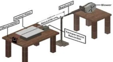
Figures 5, 6 and 7 show the experimental setup. Figure 5 shows a blower injecting air to a flat plate of mild steel using three different-shaped nozzles (Circular, Elliptical and Rectangular). Figure 6 shows a mild steel plate is being heated by using a plate heater. Figure 7 shows manometer reading recording arrangement.
2.1.1 Apparatus required
Different apparatus used during experiment are:
2.1.2 Description of the Nozzles Figure 2 shows circular nozzle. Nozzle length= 500 mm Inner diameter= 7.5 mm Outer diameter= 8.5 mm Thickness= 1 mm
Equivalent inner diameter, de = 7.5 mm
Figure 3 shows Elliptical nozzle. Nozzle length= 500 mm
Major inner diameter, a= 10.7 mm Major outer diameter= 11.7 mm Minor inner diameter, b= 5.25 mm Minor outer diameter= 6.25mm Thickness= 1 mm
Equivalent inner diameter, de = 1.55 (A0.625/P0..2) = (44.12)0.625/(26.48)0..2 = 7.5 mmwhere,
A Blower Temperature recorder Mild Steel plate Digital manometer Plate heater Inclined manometer Thermocouple wires Stop watch
Insulation materials Pitot tube
Area, A = ab /4 (3.1416 10.75.25)/4 44.12mm 2
Perimeter, P = 2π[0.5 { a 2 2+ b 2 2}]12 = 2π[0.5 { 10.7 2 2+ 5.25 2 2
}]12
= 26.48 mm Figure 4 shows Plane nozzle. Nozzle length= 500 mm Inner width, a= 9.4 mm Outer width= 9.9 mm Inner breadth, b= 4.7 mm Outer breath= 5.2 mm Thickness= 0.5 mm
Equivalent inner diameter, de 1.30[(ab)0.625 /(a b)0.25]
=1.30[(9.44.7)0.625 /(9.44.7)0.25 7.2mm
2.2 Experiment
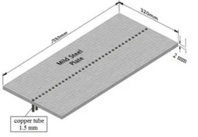
In this experiment mild steel plate is used. The nozzles were placed horizontally to the plate. Ambient air was passed through the nozzles by a blower for the purpose of cooling. Three different-shaped Wall Jets were used in this experiment, namely, Circular Wall Jet, Elliptical Wall Jet and Plane Wall Jet. Two plate heaters were used below the plate and for insulation of the plate fire clay, glass wool, ebonite sheet was used. Cork sheets were used around the frame to reduce heat loss. For getting temperature reading 35 thermocouple wires were connected to the plate by partially drilling the plate of 1.5 mm diameter. These points were taken along the axis from the center line.
The plate was heated by a plate heater electrically. After heating the plate continuously for four hours stable point temperature was obtained. Then the temperature was recorded by digital temperature recorder. Here, for taking temperature from one point to another the temperature recorder takes some time (approximately 35-40 seconds) to reach the stable position for showing the actual temperature reading of the points. For reducing time loss two digital temperature recorders were used. After taking the temperature of all the points the blower was switched on and later cooling stable point temperature was obtained. The time for single degree temperature decrease was counted by a stop watch. Then the temperatures of all the points were recorded. At the time of temperature reading in the plate pressure reading also recorded with pitot tube adjustment. Both inclined manometer and digital manometer were used to take pressure reading. The readings from digital manometer and inclined manometer were compared and approximately correct value was taken. For taking temperature and pressure reading the time required was approximately 25-27 minutes for each Re. The same procedure was repeated for different Re tests.
2.3 Theoretical Study
Reynolds Number,Re vde/ , v= 2gH, H p/g ,where,
= Density of air, kg/m3
v = Mean centerline velocity of the nozzle, m/s de= Equivalent diameter, m
µ = Dynamic viscosity of air, Ns/m2
= 1.88 × 10⁻⁵ kg/m.s [at atmospheric temperature, 34oC]
g = Acceleration due to gravity, m/s2 H = Manometric height, m
p = Manometric pressure, N/m2 Calculation of heat flux, q″: Q = k.A (∆T/∆y)
or, q″ = Q/A= k (∆T/∆y) where,
Q = Heat transfer rate, W q″ = Heat flux, W/m2
∆T = Temperature difference, 0C
∆y = Plate thickness, m
k = Thermal conductivity of plate, W/m K Calculation of heat transfer coefficient, h: h = q″/ (Ts - T∞)
h = Heat transfer coefficient, W/m2 0C Ts = Surface temperature, 0C
T∞ = Ambient temperature, 0C
Calculation of local NusseltNumber,Nux:
Local Nusselt number, Nu x h(Ts T)/[Kair(Ts T)/x] hx /Kair
where,
x = center to center distance between two points, m
Kair= thermal conductivity of air, W/m K
2.3.1 Sample Calculation: q″ = k (∆T/∆y)
= 54 (6152)/(2103)
= 2.43 × 10⁵ W/m2
h = q″/ (Ts-T∞)
= 2.43 × 10⁵/ (61-34) = 9.0 × 10³ W/ m2K
air
x hx K
Nu /
= (9.0 × 103 × 20 × 10-3)/ 0.0265 = 6.792453 × 10³
m g
p
H / 740 /(1.149 9.81) 65.65
v = 2 × 9.81 × 65.65 = 35.89 m/s
16451 10 88 . 1 / ) 10 5 . 7 89 . 35 149 . 1 ( /
Re vde 3 5
where,
ρ = 1.149 kg/m3[at atmospheric temperature, 340
C] µ = 1.88 × 10⁻⁵ kg/m.s[at atmospheric temperature, 340C]
g = 9.81 m/s2
Pressure Coefficient, Cp= (p-p∞)/ (1/2 ρU∞2)
= 639.6/ (1/2 × 1.1493 × 35.892)= 0.8643 where,
p∞ = Ambient pressure, N/m2
U∞ = Free stream velocity of air, m/s
III.
RESULTSAND DISCUSSION
Span-wise Distanceis the ratio of local distance and dimensional parameter. For Circular Wall Jet Span-wise distance is X =x/d, where x is local distance and d is diameter of the circular nozzle. When Elliptical Wall Jet is set along major axis then Span-wise distance X =x/b, where x is local distance and b is the minor axis distance from centre.When Elliptical Wall Jet set along minor axis then Span-wise distance X =x/a, where x is local distance and a is the major axis distance from centre.When Rectangular Wall Jet nozzle is set vertically then Span-wise distance X =x/w where, x is local distance and w is the width of nozzle.When Rectangular Wall Jet nozzle is set flat then Span-wise distance X =x/l where, x is local distance and l is the length of the nozzle Figures8, 9 and 10 showsVariation of Cpwith Span-wise Distance for Circular Wall Jet, Elliptical Wall Jet and
Plane Wall Jet respectively.They show that for every Wall Jet,Cpincreases with the increase of Re.
Figures11 and 12 shows Variation of Cpwith Span-wise Distance for Re=16451and Re=11945
respectively. They show that decrease of Cp for Elliptical and Circular Wall jets are approximately
logarathemically and and almost the same. Decrease of Cpof Circular Wall Jet is a little bit more than Elliptical
wall Jet. For Rectangular Wall jetCp decreases rapidly than the other two Wall jets.If rate of decrease of Cp is
more rapid then decrease of rate of heat transfer will be rapid. As a reasult, cooling will be slowerusing rectangular Wall jet than Elliptical and Circular Wall jets [19]. It is clear that heat transfer rate as well as cooling is more rapid for Elliptical Wall jet than Circular and Rectangular Wall jet for high Re (turbulent flow).
Figure 13 shows Variation of Cpwith Span-wise Distance at Re= 8764.Here,rate of decrease of Cp of Circular
Wall Jet is slower than Rectangular and Elliptical Wall jets. Among them, Cp for Rectangular Wall Jet falls
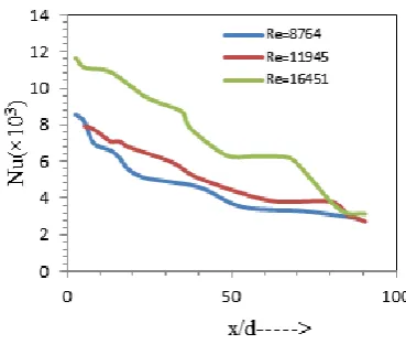
0.02678 and 0.018569.Figure 14 showsVariation of Nu with Span-wise Distance for Circular Wall Jet.It explains that the heat transfer characteristics vary with the variation of Re. Heat transfer rate increases with the increase of Re. The heat transfer rate decreases as the distance from the axis line increases. Here, high heat transfer rate is recored at the center point due to increased centerline velocity.Figure 15 showsVariation of Nu with Span-wise Distance for Elliptical Wall Jet. It explainsthat along major axis heat transfer rate is higher than the other Wall Jets. But, along minor axis heat transfer rate will not be as much higher like that. The variation of Re has reasonable effect on the heat trasfer characteristics.Figure 16 showsVariation of Nu with Span Wise Distance for Plane Wall Jet. It also means that for the Rectangular Wall Jet heat transfer characteristics is not so much satisfactory as like as the other two. When nozzle is set vertically heat transfer rate is found to be higher than when it is set in flat position.Figures 13, 14, 15 and 16 show that rate of decrease of Cp is proportional to
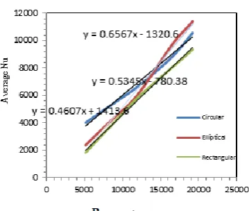
rate of decrease of heat transfer.Figure 17 showsVariation of Nu with Span-wise Distance for Re=8764. It is found thatthe heat transfer characteristics of Circular and Elliptical Wall Jets are approximately the samewithin the span-wise distance of 40. But Circular Wall Jet heat transfer characteristics is much satisfactory than that of Elliptical Wall Jet throughout the entire Span-wise Distance. Rectangular Wall Jet is less effective than the other two.Figure 18 and 19 are Variation of Nu with Span-wise Distance for Re=11945 and Re= 16451 respectively. In Figure 18, it is found that the heat transfer characteristics of Circular and Elliptical Wall Jets are approximately the same within span-wise distance 40-60. But in Figure 19, it is found that for Elliptical Wall Jet heat transfer characteristics is higher thanthat of Circular Wall Jet throughout the entire Span-wise Distance. Rectangular Wall Jet is always less effective than the other two.Figure 20 shows Variation of Nu with Re. It singnifies that average Nu of Circular Wall Jet increases more rapidly than Elliptical and Rectangular Wall Jets between Re of 4000 to 15000. But above Re = 15000, the average Nu of Elliptical Wall Jet increases more rapidly than the other two Wall Jets.
IV.
CONCLUSION
Among Circular Wall Jet, Elliptical Wall Jetand Plane Wall Jet, Circular Wall Jet is most effective for cooling purpose at Re<14000 and Elliptical Wall Jet is most effective at Re>14000 along major axis.Cp of
Circular, Elliptical and Plane Wall Jets decreases logarithmically and its order of decreasing is found Elliptical> Circular>Plane for Re>14000flow and Circular>Elliptical>Plane for Re<14000 flow.That is, heat transfer rate is higher in Circular Wall jet than Elliptical and Rectangular Wall jets for Re<14000. On the other hand, heat transfer rate is higher in Elliptical Wall Jet than Circular and Rectangular Wall jets for Re>14000.In general, Elliptical Wall Jet is most efficient for cooling along major axis.
V.
REFERENCES
[1] D. Li, X. Xia, F. Sun, Numerical Study on Heat Transfer Characteristics of Gas Turbine Coated Blades,
978-1-4244-4812-8, IEEE, March 2010, 1 – 4
[2] Yonghan Kim, Yongchan Kim, Heat transfer characteristics of flat plate finned-tube heat exchangers with large fin pitch, International Journal of Refrigeration,28, 14 April 2005, 851–858.
[3] A. Achaichai, T.A.Cowell, Heat Transfer and Pressure Drop Characteristics of Flat Tube and Louvered Plate Fin Surfaces, Department of Mechanical and Production Engineering, Brighton, Polytechnic, Moulsecoomb, Brighton, UK.
[4] Vinayak S. Powar, Prof. M. M. Mirza, Performance of Louver Fin Pattern as Extended Surface Used To Enhance Heat Transfer – A Review, International Journal of Engineering Research and Applications ISSN: 2248-9622, 3(6),Nov-Dec 2013, 1409-1413.
[5] VadirajKatti, S.V. Prabhu, Experimental study and theoretical analysis of local heattransfer distribution between smooth flat surface andimpinging air jet from a circular straight pipe nozzle, Department of Mechanical Engineering, Indian Institute of Technology, Bombay, Powai, Mumbai 400 076, India. [6] J.N.B. Livingood, P. Hrycak, Impingement heat transfer from turbulent air jets to flat plates – a literature
survey, NASA Technical Memorandum (NASA TM X-2778), 1970.
[7] James W. Gaunter, John N.B. Livingood, Peter Hrycak, Survey of Literature on flow Characteristics of a Single Turbulent Jet Impinging on Flat plate, NASA TN D-5652, February, 1970.
[8] R. Gardon, J. Cobonpue, Heat transfer between a flat plate and jets of air impinging on it, Int. Develop. Heat Transfer, ASME (1962), 454–460.
[9] D.H. Lee, J. Song, C.J. Myeong, The effect of nozzle diameter on impinging jet heat transfer and fluid flow, J. Heat Transfer 126 , 2004, 554–557.
[10] M. Poreh, Y.G. Tsuei, J.E. Cermak, Investigation of a turbulent radial wall jet, J. Appl. Mech. 34,
1967,457–463.
Figures
Figure1: Configuration and Nomenclature For Plane Wall Jet
Figure 2: Schematic Diagram of Circular Wall Jet
Figure 3: Schematic Diagram of Elliptical Wall Jet Figure 4: Schematic Diagram of Plane Wall Jet
Figure 7: Setupof the Plate for Pressure Reading Figure 8: Variationof Pressure Coefficient With Span-wise Distance for Circular Wall Jet
Figure 9: Variation of Pressure Coefficient with Span-wise Distance for Elliptical Wall Jet
Figure 10: Variationof Pressure Coefficient With Span-wise Distance for Plane Wall Jet
Figure 11:Variation of Pressure Coefficient with Span-wise Distance at Re=16451
Figure 13:Variation of Pressure Coefficient with Span-wise Distance at Re=8764
Figure 14: Variation of Nu with Span-wise Distance for Circular Wall Jet
Figure 15: Variation of Nu with Span-wise Distance for Elliptical Wall Jet
Figure 16: Variation Of Nu with Span-wise Distance for Plane WallJet
Figure 17:Variation of Nu with Span-wise Distance at Re=8764
Figure 19:Variation of Nu with Span-wise Distance at Re=16451