IoT based Automated Traffic Light Control
System for Emergency Vehicles using LoRa
Divij N Divya K
Department of Computer Science & Engineering Department of Computer Science & Engineering Sapthagiri College Of Engineering, Hesaraghatta,
Bengaluru- 560057, India
Sapthagiri College Of Engineering, Hesaraghatta, Bengaluru- 560057, India
Anuradha Badage
Department of Computer Science & Engineering
Sapthagiri College Of Engineering, Hesaraghatta, Bengaluru- 560057, India
Abstract
There is a serious issue of Emergency Vehicles being stuck at intersections due to traffic congestion or scheduled traffic signal. This may result in delay in motion or the Emergency Vehicle may remain in statutory position. Otherwise, if the emergency vehicle ever tries to override the signal, it may result in accident or traffic congestion. To overcome this problem automated traffic control system is proposed. The system is designed to find a cost efficient and accurate solution to save lives. In the system, siren of the approaching emergency vehicle is priorly sensed by using smart objects and the traffic lane in which the emergency vehicle is approaching is made free by halting the traffic in other lanes of the intersection.
Keywords: Acoustic Sensors, Congestion Control, IoT, LoRa, Object Detection
________________________________________________________________________________________________________
I. INTRODUCTION
In today’s world traffic being the main issue in concern, is creating innumerable problems to the general life. Apart from the common issues of congestion, it poses serious hindrance to the normal functioning of emergency vehicles. Emergency vehicles have to be prioritized in comparison with all other vehicles, but either due to unavoidable situations or due to self-centred motorists emergency vehicles do not reach their destinations on time. Delayed arrival of emergency vehicles may pose threats to life. Apparently, there has to be a system which detects the emergency vehicle prior to its arrival at the junction and clear the traffic ahead of it before-hand. This may minimize the delays and facilitate the needy during their emergency. Unfortunately, there are no efficient measures taken to deal with this problem in most of the countries including India. And thus either emergency vehicles may remain statutory or may override the signal. In case the emergency vehicles override the traffic signal, there are high possibilities of encountering accidents. Recent development of technology has led us to IoT, which provides an efficient method to address these issues. The difficulties faced by emergency vehicles can be avoided using Automated Traffic Control System. One or more smart object(s) are installed in every lane of a particular intersection which is designed to sense the siren of approaching emergency vehicle which triggers the camera to capture images and to verify if the vehicle is an emergency vehicle or not by comparing the obtained image with the stored data set . If the vehicle is identified as an emergency vehicle then the signal is transmitted to the Decision Support System. The Decision Support System clears the traffic by identifying the lane through which the emergency vehicle is approaching. All other signal lights of that junction are turned to red. Sound detection sensors are used to identify the departing emergency vehicle, after which traffic lights are flipped back to their normal functioning. The emergency vehicle is detected prior its arrival thus the system prevents latency. The traffic data is stored into cloud by the Decision Support System and can be used for data analysis.
II. LITERATURE SURVEY
Traffic light control system designed by Levi L. Rose [1] used only for emergency vehicle in which sensor is installed in every emergency vehicle to transmit the signal to the receiver placed at every traffic light intersection. When emergency vehicle reaches the traffic light intersection, signal code will be sent to the receiver. The receiver demodulates the code and red traffic light will get triggered at the junction. Thus, emergency vehicle will have special route from other vehicles to reach the destination.
Traffic light control system designed by M. R. Smith et al [2] a display system which indicated the lane in which the emergency vehicle was approaching the junction. A transmitter was installed on all the emergency vehicles and an I R receiver at the intersection. A master controller was used to process the signal and control the traffic flow. The departure of the emergency vehicle was also detected and displayed on the display system by the master controller.
wireless transmission mode using radio waves. Once the controller detects the RF signals it generates an emergency signal code, which is reverted back to normal after the emergency vehicle leaves the junction.
III. PROPOSED SYSTEM
In India the siren sound of all emergency vehicles are preset and follows a similar pattern. The siren sound repeats in two tones. The tones are 960 Hz and 770 Hz, and these are repeated at every 1.3 sec period. The siren sound is affected by the Doppler Effect and varies its frequency due to the motion of the emergency vehicle.
The proposed system works in two phases. First phase is about detection of emergency vehicle and second phase is all about taking the action at the intersection.
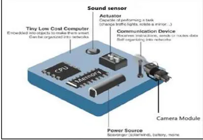
The system uses the sound detection sensor, camera and microcontroller for processing the data. The proposed system uses the LoRa technology for communication. Data set of different emergency vehicle patterns will be stored at the smart object, which will be used to compare the current emergency vehicle with the existing dataset. Camera will be installed in the smart object and will be well positioned to capture only required portion of the road.
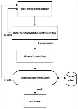
In first phase the smart object detects the emergency vehicle on the road through:
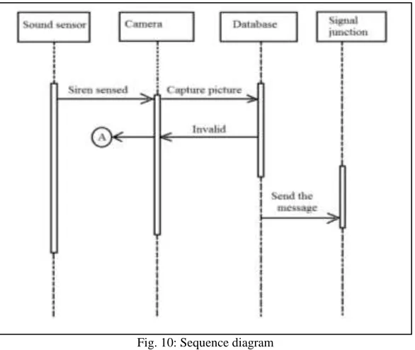
If the emergency vehicle is on the way towards the signal then the smart object which is placed (200 m) away from the signal junction will detect the siren sound of emergency vehicle by using sound detection sensor.
Next process in the smart object is about matching the moving object on the road with the stored dataset. The camera will be set to capture the pictures of vehicles on the road as soon as the Smart object detects the sound.
If both the conditions satisfy, then smart object sends the message to the Decision Support System which is centralized in the Signal junction.
Second phase is about taking the decision. Signal junction will be installed with the Decision Support System. This system receives the signals from the smart objects which are placed on the different roads which are going to intersect in the junction. All the smart objects and Decision Support System will be arranged in the star topology. The Decision Support System at the center is responsible for taking the appropriate decision about clearing the traffic on the lane where the emergency vehicle is travelling.
Decision Support System will be installed with Acoustic Sensors near the intersection which works on Receding Doppler Effect, to make sure that the emergency vehicle has crossed the junction so it can be reverted back to its normal functioning.
Decision Support System is also responsible for receiving the data, processing the data, storing the data to the cloud, as well as transmitting the data to the next Decision Support System.
Fig. 1: System Architecture
The smart object consists of Sensors, Camera, Storage, Processing unit and Communication device. Decision Support System is a processing unit with actuator.
Fig. 3: Connecting Arduino Nano with LoRa
Arduino Nano which is compatible with LoRa transceivers is used in Smart Object to match the obtained frequency and image with the Dataset. Arduino Nano board consists of Microcontroller ATmega328 processor, Flash Memory 32 KB of which 2 KB used by bootloader, SRAM is 2 KB, EEPROM is 1 KB and has a clock speed of 16 MHz.
Fig. 4: Acoustic sensor used as sound detection module
Acoustic sensors which have an audible range upto 10 meters continuously detect the audio signals and try to match with the audio frequency stored in dataset using bandpass filter.
Fig. 5: CMU cam5 with Arduino Nano
Communication Technology
LoRa Technology
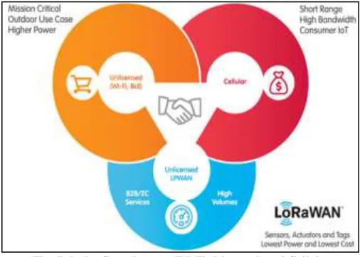
LoRa has been used for communication between sensors and the gateway. LoRa (Long Range) is a patented digital wireless data communication technology developed by Cycleo of Grenoble, France, and acquired by Semtech in 2012. It is a new wireless protocol designed specifically for long-range, low-power communications. LoRa stands for Long Range and is mainly targeted for M2M and IoT networks. This technology will enable public or multi-tenant networks to connect a number of applications running on the same network. LoRa Technology enables smart IoT applications that solve some of the biggest challenges facing our planet: energy management, natural resource reduction, pollution control, infrastructure efficiency, disaster prevention, and more. LoRa Technology is the DNA of IoT, creating a Smarter Planet. It offers compelling features for IoT applications including long range, low power consumption and secure data transmission. The technology can be utilized by public, private or hybrid networks and provides greater range than cellular networks. Each LoRa gateway has the ability to handle up to millions of nodes. The signals can span a significant distance, which means that there is less infrastructure required, making constructing a network much cheaper and faster to implement. LoRa also features an adaptive data rate algorithm to help maximize the nodes battery life and network capacity. The LoRa protocol includes a number of different layers including encryption at the network, application and device level for secure communications.
Fig. 6: LoRa Access Technology
LoRa Complements Wi-Fi, Bluetooth and Cellular:
Like Wi-Fi, LoRa operates in the unlicensed band and supports indoor applications: like cellular, LoRa Technology is highly secure from end devices to the application server, and is suitable for outdoor applications. LoRa Technology combines these features of Wi-Fi and cellular networks to offer an efficient, flexible and economical connectivity solution ideal for IoT applications whether indoor or outdoor and installed in public, private or hybrid networks. Simple sensor data can fuel analytics platforms, such as those for artificial intelligence and machine learning. These require data diversity which is made possible by low-cost LoRa- enabled sensors.
Fig. 7: LoRa Complements Wi-Fi, Bluetooth and Cellular
leverages the unlicensed radio spectrum in the Industrial, Scientific and Medical (ISM) band. The specification defines the device-to-infrastructure of LoRa physical layer parameters and the LoRaWAN protocol, and provides seamless interoperability between devices.
Algorithm
1) Start
2) Detect the sound of Emergency Vehicle 3) If the frequency matches then set the camera 4) Capture the selected road image with vehicles 5) Compare the image with the dataset.
6) If there is match for emergency vehicle with the vehicle on the road then send the message to the DSS 7) After receiving the message from smart object, DSS checks for the sender address.
8) DSS takes the appropriate decision by clearing the lane traffic of the requesting smart object. 9) If any new message from any other or same smart objects then go to step 7.
Once the emergency vehicle passes away from the central junction (intersection), data will be added to cloud and normal routine of controlling the congestion will be carried out.
Dataflow
Fig. 8: Data Flow diagram between smart object and the Decision Support System.
Fig. 9: Depicts the working of Decision Support System.
Decision Support System takes the decision to clear the lane based on the source address of the arrived packet. It waits for sound detecting sensor to send the message, after which the traffic signal is reverted back to its normal functioning, illustrated in above figure.
Fig. 10: Sequence diagram
IV. CONCLUSION AND FUTURE WORKS
The system is dedicated to resolve the most important issue of emergency vehicles being delayed due to slow moving traffic or remain stationed for a long time. The proposed method is applicable to detect a police car siren, emergency vehicle siren or a fire-fighting vehicle siren.
The reference papers considered during literature survey included sensors in every vehicle, after the arrival of the emergency vehicle a fixed time quantum was set to revert back to normal functioning which has many demerits. The above issues are resolved in a cost efficient way by installing smart objects at the intersection and using long-range, low-power LoRa. Sound detection sensors are used to sense the departure of emergency vehicles and eventually flip back the traffic lights to their normal functioning. The system can be extended to any number of lanes. Decision support system monitors the traffic and also stores the data onto the cloud. Thus, this data can be accessed and surveyed for future enhancement.
The system may further be developed in future by developing a dynamic web or mobile application as an interface through which the system can be controlled, both automatically and manually in a smarter way. Automated message system may also be included which can be used to alert the driver about the next free lane from the intersection which leads to the destination. Communication may be established among the Decision Support Systems in highly populated areas to alert the upcoming junctions for immediate action.
REFERENCES
[1] Levi L. Rose, “Emergency Traffic Control System with Security Transmission Coding”, United States Patent, April 5th, 1997.
[2] Michael R. Smith, Paul J. Davidson and Henry L. Pfister, “Emergency Vehicle Warning and Traffic Control System”, United States Patent, October 4th, 1998.
[3] N. M. Z. Hashim , A. S. Jaafar , N. A. Ali , L. Salahuddin , N. R. Mohamad , M. A. Ibrahim K. Elissa, “Traffic Light Control System for Emergency Vehicles Using Radio Frequency”, IOSR Journal of Engineering (IOSRJEN), Vol. 3, Issue 7 (July. 2013)
[4] Takuya Miyazaki, Yukhi Kitazono and Manabu Shimakawa, “Emergency vehicle siren detector using FFT on dsPIC”. Proceedings of the 1st IEEE/IIAE International Conference on Intelligent Systems and Image Proccessing 2013. (references)
[5] Gowram Iswarya Assistant Professor, School of Civil Engineering, REVA University, Bengaluru Bharath H P Assistant Professor, School of Electronics and communication Engineering, “Sound Sensors to Control Traffic System for Emergency Vehicles”, REVA University, Bengaluru. V. Viharika Reddy Assistant Professor, School of Civil Engineering, REVA University, Bengaluru. Published at International Journal of Applied Engineering Research ISSN, Volume 13. (references)