148 | P a g e
FUZZY LOGIC TECHNIQUE BASED SHUNT ACTIVE FILTER
FOR HARMONIC MITIGATION
Uma M. Chavan
Student Member, IEEE Department of Electrical engineering Rajarambapu Institute of Technology
Islampur-415409, India. [email protected]
A. R. Thorat
Department of Electrical engineering Rajarambapu Institute of Technology
Islampur-415409, India. [email protected]
Abstract—Nowadays nonlinear loads are increasing day by day due to industriliasation. Power quality problems increases due to these nonlinear loads.Major power quality problem is the current harmonics.Shunt active filter (SHAF) is used to reduce the current harmonics. Response and the accuracy of filter depends on the method used for the extraction of reference current. A new topology has been proposed in this this paper to minimize the current harmonics by controlling shunt active filter using fuzzy logic controller (FLC) with instantaneous active and reactive current theory (𝐢𝐝 𝐚𝐧𝐝 𝐢𝐪)within the limit of IEEE Std.519.
Under unbalance supply voltage conditions simulation is done with fuzzy logic controller and synchronous reference frame technique. To analyze the performance of SHAF three phase four wire (3P4W) system is considered.Simulation result shows that Fuzzy controller technique gives the best performance under unbalanced voltage conditions.
Keywords—Power Quality, Harmonic Compensation,Shunt Active Power Filter,Fuzzy Logic Controller,Synchronous Reference Frame(SRF).
I. INTRODUCTION
Presently, need of power is increased due to globalization and industrialization. The use of power electronic devices such as converters, switching devices and nonlinear loads has been increased. The devices like cycloconverters, computers, rectifiers, printers, arc furnaces, variable speed drives,faxes, etc. introduces the harmonics in the power system. These nonlinear loads draw current which is nonlinear in nature from the ac mains and source. Due to these loads, harmonics get injected in the system. Due to presence of harmonics in the system harmonics it badly affects the power system and may have chances to damage of equipment’s. It reduces the quality of power by increasing the reactive power and total harmonic distortion. It causes voltage flicker, voltage sag, poor power factor, increased losses, voltage swell, voltage regulation etc.[1-2]. In the communication network, disturbances occur due to harmonics. Problems related to power quality are
increasing, therefore it is essential to reduce these problems by mitigating harmonics in the system.
For reducing the problems related to harmonics, filters are implemented in the system. Traditionally, passive filters are widely used for reducing the harmonics. But there are some drawbacks such as resonance problem, slow in response, no scope for programming and occupy more space etc. An installed passive filter scheme is valid for the present load and network configuration. If there is any change in the network, it requires redesign for addition of filters [3]. However active filters are reliable and robust. In networkif any changes are occurred, working operation of active filters are not affected and additional filters can be connected in parallel. For compensating the current and voltage related problems, active filters are used. For avoiding the resonance problem, reactive power compensation and harmonic compensation, active filters are mostly used [4].
149 | P a g e Active filter performance is based on the technique which is used for extracting the reference current for controlling the inverter switches and DC voltage. Traditionally, PI controller is used for control of filter. It requires mathematical model in linear nature which is difficult to obtain [6]. Under load disturbance and system parameter variations, PI controller not give a better performance. Fuzzy controller is introduced over traditional controllers. Advantages of FLC [7]:
i. No need of accurate mathematical model ii. Non-linearity can handle easily
iii. Robust control
iv. Can work with imprecise inputs
This paper provides,a fuzzy logic controller with triangular membership function.For unbalance voltage situation, synchronous reference frame i.e.instantaneous active and reactive current method is used for extracting reference current. Section III describes the id and iq method.Section IV defines the
FLC. Circuit configuration utilize for simulation is described in section V with results. Under unbalancedcondition, MATLAB Simulink model justifies the operation of shunt active filter.
II. SHUNT ACTIVE POWER FILTER
Fig.1. Structure of Shunt active power filter
For compensating load side current harmonics, filter injects harmonic current which is equal in magnitude but opposite in phase. Fig.1 shows the principle ofshunt active filter.A voltage source inverter (VSI) is acts as a SAPF.VSI is controlled such
that it inject or absorb a compensating current Ic to or from the system, so as to cancel the current harmonics present on the AC side. The VSIwith series connected inductor suppresses the ripple current.
Igrid= Ifilter+ Iload (1)
III. SYNCHRONOUS REFERENCE FRAME THEORY
Synchronous reference theory i.e. instantaneous active and reactive current (id and iq) theory is used for
controlling the shunt active filter synchronous reference frame i.e. instantaneous active and reactive current(id and iq) theory is used. Advantage of this method
is, it gives the better performance than the other control technique during unbalanced supply voltage condition [8],[9].
By using synchronous reference theory three phase load currents are converted into dq0. Parks transformation is used to isolate the content of harmonics from the fundamental current. The parks transformation is defined by,
[ id
iq
io
] = √2
3
[
cosθ cos (θ−23π) cos (θ+ 2π
3)
−sinθ −sin (θ−2π
3) −sin (θ+ 2π 3) 1 √2 1 √2 1 √2 ] [ ia ib ic ](2)
Where, θ is angular position of synchronous reference. Here, id and iqare the instantaneous active and reactive
current component. Instantaneous active current (id) and
reactive current (iq) contains AC and DC component. A
high pass filter i.e. a low pass filter with feed-forward effect is used for extracting the harmonic reference current from the load current.Synchronous reference currents isresolved in two components as,
id = ĩ + id ̅d(3)
iq = ĩ + iq ̅q (4)
The ‘ ͞ ’sign indicates the fundamental component and‘~’indicates the harmonic contents.
The harmonic contents are utilize for the current extraction. SAPF reference current will be then,
[id
∗
iq∗] = [
ĩd
ĩq] (5)
Inverse park transformation is used to calculate the three phase systemSAPF currents, as follows:
[ ia∗
ib∗
ic∗
] = √2
3[
cosθ −sinθ
cos (θ−2π
3) −sin (θ− 2π
3)
cos (θ+2π
3) −sin (θ+ 2π
3)
] [id
∗
iq∗] (6)
150 | P a g e s
Fig.2.Principle of synchronous reference frame
IV. FUZZY LOGIC CONTROLLER
Fig.3. Structure of Fuzzy Logic Controller
The internal structure of fuzzy controller is shown in Fig.3. It consist of four stages-
a. Fuzzification b. Rule base c. Fuzzy inference d. Defuzzification
In real world, classic and crisp variables are present. For applying fuzzy inference, we need input in linguistic variables values. In fuzzy sets, linguistic values are expressed by degree of membership. Converting the numerical input to the linguistic values is known as Fuzzification.For controlling the output variable, rule base is used in fuzzy logic system. The fuzzy rule is, IF THEN type rule with a condition and conclusion. IF THEN rule of fuzzy relates a condition describes by using fuzzy sets and linguistic variables to a conclusion or an output. Elastic conditions are used by IF part to capture knowledge. An output or conclusion is given by THEN part in the form of linguistic variables. Fuzzy inference is the process of generating a relation between the input and output applying fuzzy logic. For producing the fuzzy output set, fuzzy inference
system is applied to the set of rules in fuzzy rule. Output of the fuzzy inference system is fuzzy value. The process of converting fuzzy output into a crisp output is known as Defuzzification. In Defuzzification technique, centroid of area method is widely used in real applications. Centroid of area is covered by the curve of the membership function is calculated to the
crisp value.
Fig.4. Membership function for inputs and output
Error and change in error are the two inputs of FLC.Error is the difference in measured and reference value of the capacitor voltage.The output of the FLC is shown by control current Imax. Seven fuzzy sets are
selected for converting numerical values of input to linguistic variables.Fuzzy sets are: Negative big (NB), Negative medium (NM), Negative small (NS),zero (ZE), Positive small (PS), Positive medium (PM), and positive big (PB).
FLC is characterized as –
For each input and output there are seven fuzzy sets.
151 | P a g e Fuzzification using continuous universe of
discourse.
Implication using Mamdani's 'min' operator. For Defuzzification ‘centroid of area’ method is
used.
Fig.4 shows thetriangular membership function for each input and output. Fig.6 shows the structure of id and iq method with FLC.
V. SYSTEM PERFORMANCE
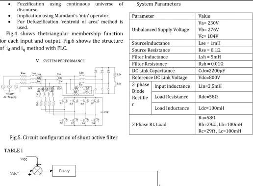
Fig.5. Circuit configuration of shunt active filter
TABLE I
System Parameters
Parameter Value
Unbalanced Supply Voltage
Va= 230V Vb= 276V Vc= 184V SourceInductance Lse = 1mH Source Resistance Rse = 0.1Ω Filter Inductance Lsh = 5mH Filter Resistance Rsh = 0.01Ω DC Link Capacitance Cdc=2200μF Reference DC Link Voltage Vdc=800V 3 phase
Diode Rectifie r
Input inductance Lin=2.5mH
Load Resistance Rdc=58Ω
Load Inductance Ldc=100mH
3 Phase RL Load
Ra=58Ω
Rb=29Ω , Lb=100mH Rc=29Ω , Lc=100mH
Fig.6. Instantaneous active and reactive current with fuzzy logic controller
Shunt active power filter with 3P4W supply system is shown in Fig.5. Table I shows the system parameters used in simulation.System consist two loads i.e. three phase diode bridge with RL and three phase RL load. To examine the performance of 3P4W shunt active power filter system, four leg VSI technique is used. For switching hysteresis controller technique is used.Shunt active filter performance is analyze with unbalance supply voltage condition with fuzzy controller.
CASE- Unbalanced Condition
152 | P a g e shown in Fig. 7(d). Load current and DC link voltage are shown in Fig. 7(e) and Fig. 7(f).
(a)
(b)
(c)
(d)
(e)
(f)
Fig.7. System Waveforms under Unbalanced condition
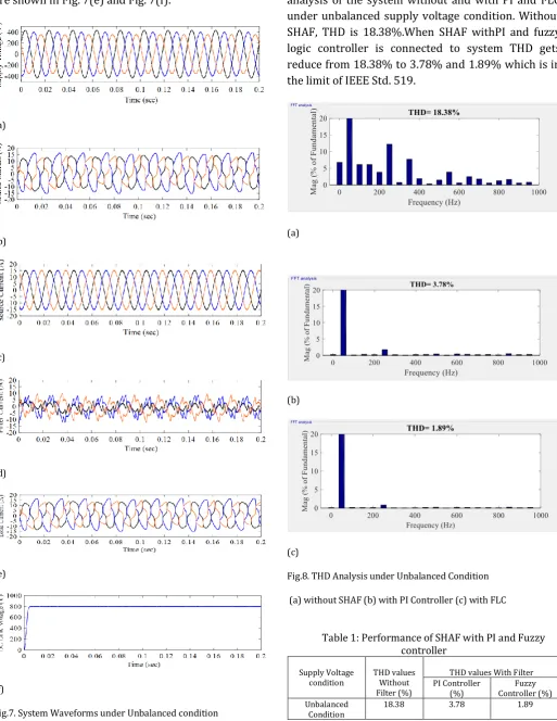
Fig. 8(a), Fig. 8(b) and Fig. 8(c) shows the FFT analysis of the system without and with PI and FLC under unbalanced supply voltage condition. Without SHAF, THD is 18.38%.When SHAF withPI and fuzzy logic controller is connected to system THD gets reduce from 18.38% to 3.78% and 1.89% which is in the limit of IEEE Std. 519.
(a)
(b)
(c)
Fig.8. THD Analysis under Unbalanced Condition
(a) without SHAF (b) with PI Controller (c) with FLC
Table 1: Performance of SHAF with PI and Fuzzy controller
Supply Voltage
condition THD values Without Filter (%)
THD values With Filter PI Controller
(%) Controller (%) Fuzzy Unbalanced
153 | P a g e Table 1 shows the performance of shunt active filter with PI controller and Fuzzy controller. Both of the controller are compensates the current harmonics. It is shown that Fuzzy controller is gives better performance than PI controller.
VI. CONCLUSION
The main aim of this paper is to eliminate the current harmonics induced by nonlinear load according to IEEE Std. 519 limit. To reduce the current harmonics FLC with id and iq method is
proposed. In FLC, triangular membership function
and Mamdani min method is
used.The id and iq method improves the SHAF
performance in unbalanced condition. DC link voltage of capacitor is controlled by FLC. Four leg VSI based shunt active filter is simulated. From simulation results, current harmonics are effectively mitigated by using FLC and these are within the limit of IEEE Std. 519.
REFERENCES
[1] Bhim Singh, Ambrish Chandra, Kamal Al-Haddad and B.N.Singh, “An
Improved Control Algorithm of Shunt Active Filter for Voltage Regulation,Harmonic Elimination,Power Factor Correction and Balancing of Nonlinear Loads,”IEEE Trans. On power electronics, vol. 15, no. 3, pp. 495-507, May 2000.
[2] Hatem Zeineldin, Parag Kanjiya and Vinod Khadkikar, “Optimal
control of Shunt Active Power Filter to meet IEEE Std. 519 Current Harmonic Constraints under Nonideal Supply Condition,” IEEE Trans.
On Power Electronics, vol. 62, no. 2, February 2015.
[3] J.C.Das, “Passive Filters-Potentialities and Limitations” IEEE Trans. On
Industry Applications, vol. 40, no. 1, pp.232-241, January 2004.
[4] A. Chandra, K.Haddad and Bhim Singh, “A Review of Active filters for
Power Quality Improvement,” IEEE Trans. On Industrial Electronics, vol. 46, no. 5, pp. 960-971, October 1999.
[5] Vinod Khadkikar, Mohammed Qasim and Parag Kanjiya,
“Artificial-Neural-Network-Based Phase-Locking Scheme for Active Power Filters,”IEEE Trans. Industrial Electronics, vol. 61, no. 8, August 2014.
[6] Suresh Mikkili and A. K. Panda, “PI and Fuzzy Logic Controller based
3-phase 4-wire Shunt active filter for mitigation of Current harmonics with Id-Iq Control Strategy,”Journal of power Electronics (JPE), vol. 11, no.6, November 2011.
[7] A. K. Panda and Suresh Mikkili, “Types-1 and -2 fuzzy logic
controllers-based shunt active filter Id–Iq control strategy with different fuzzy membership functions for power quality improvement using RTDS hardware,” IET Power Electron., vol. 6, pp. 818–833, February 2013.
[8] Gil Marques, Pedro Verdelho and Vasco Soares, “An Instantaneous
Active and Reactive Current Component Method for Active Filters”
IEEE Trans. on Power Electronics, vol. 15, no. 4, July 2000.
[9] Charles. S and G.Bhuvaneswari, “Comparison of Three Phase Shunt
Active Power Filter Algorithms,” International Journal of Comp. and