Collaborative Agent-Based Systems
Shawn A. Bohner
1, Denis Graˇcanin
1, Michael G. Hinchey
2and Mohamed Eltoweissy
31Virginia Tech Dept. of Computer Science Blacksburg, VA 24061, USA
2Loyola College in Maryland Dept. of Computer Science Baltimore, MD 21210, USA
3Virginia Tech Dept. of Electrical and Computer Engineering Arlington, VA 22203, USA
Abstract
As demands for behaviorally sophisticated software grow, agent-based systems are increasingly being em-ployed. Software agents are frequently applied to large, complex systems that involve interdisciplinary develop-ment teams. These complex systems have proved to be challenging to develop and evolve, even for the most competent software engineers. Taking lessons learned in other engineering disciplines such as computer and architectural engineering we investigated a model-based engineering approach called Model-Driven Architecture (MDA) to automate, whenever possible, the develop-ment and evolution of agent-based applications. In our investigation, we use the Cognitive Agent Architecture (Cougaar); one of the most mature and sophisticated col-laborative agent-based architectures. MDA and Cougaar served as the primary components and implementation platform for our research. In this paper we present our approach and demonstrate how MDA is effective for producing sophisticated agent-based systems. A key challenge was found in designing a flexible meta-model framework that would accommodate both top-down do-main information and bottom-up platform specific con-structs, as well as the transformations and mappings be-tween them. We employed a General Domain Application Model (GDAM) as the platform-independent model layer and General Cougaar Application Model (GCAM) layer
as the platform specific model respectively. Domain-level requirements are formulated using a XML Process Definition Language (XPDL) based graphical editor and are the refined through a series of model transformations (via the underlying metamodel) to systematically gener-ate the agent-based software system. Through an illustra-tive case-study, we report on the feasibility, strengths and limitations of the model-based approach as it was inves-tigated with the Cougaar.
1. I
NTRODUCTIONsys-tems that require very complex behaviors and decisions. Suffice it to say, these agent-based applications are so-phisticated, complex, and very hard to develop.
Interdisciplinary development of these systems has emerged as a way to ensure that relevant requirements are rendered properly as the abstract models from the prob-lem domain evolve into increasingly more detailed and complete ones used to generate software. Development and maintenance environments must support this inher-ent part of producing today’s highly integrated and com-plex computing systems. Software architecture provides a framework to understand dependencies that exist between the various components, connections, and configurations reflected in the requirements. These emergent technolo-gies provide a reasonable basis for addressing complexity issues by separating concerns (integration, interoperabil-ity, decision support, and the like) and allowing agents to provide the necessary processing. The task orienta-tion, coupled with intelligent agents, provides a strategic and holistic environment for designing large and complex computer-based systems. These systems may support logistics management, battlefield management, supply-chain management, to mention but a few.
The Cognitive Agent Architecture (Cougaar) can be characterized in the same way. Cougaar is an open source, distributed agent architecture [2], a result of approxi-mately eight years of development for the Defense Ad-vanced Research Projects Agency (DARPA) under the Advanced Logistics Program (ALP) and the Ultra*Log program [3]. The primary focus of development has been on very large-scale, distributed applications that are char-acterized by hierarchical task decompositions, such as military logistics planning and execution. In addition, during the last four years, particular attention has been given to fault tolerance, scalability, and security.
Many of today’s software systems exhibit characteris-tics that align with agent systems. They are task-oriented and often adaptive, and may involve autonomic behav-iors, or engage in collaborative or competitive activi-ties. These and other aspects make it challenging to de-velop and evolve agent-based systems in a timely fash-ion. To address this key challenge, we investigate the Ob-ject Management Group’s (OMG) Model Driven Archi-tecture (MDA) approach [6, 17, 24], which aims at sepa-rating application logic from the underlying technologies to improve reusability, portability and development pro-cesses. The underlying premise is that business knowl-edge should be long-lived, whereas technical concerns are generally short-lived and limited to a given technology. MDA provides a means of automating the development process to a significant degree. Additionally, we examine how changes to the software system are characterized and reasoned about in the model-based environment.
In some respects, MDA is an advanced
perspec-tive on well-known essential systems development con-cepts practiced over the years (albeit frequently practiced poorly). OMG promotes MDA advocating Unified Mod-eling Language (UML) as the modMod-eling technology at the various levels. MDA endeavors to achieve high portabil-ity, interoperabilportabil-ity, and reusability through architectural separation of concerns; hinging on the long-established concept of separating the operational system specification from the details of how that system implements those ca-pabilities on its respective platform(s). That is, separate the logical operational models (external view) from the physical design for platform implementations.
Development of agent-based systems can be thought of as the evolution of abstract requirements into a concrete software system. Starting with requirements that must be refined and elaborated, the system’s evolution is achieved through a successive series of transformations. For non-trivial systems, this can be complex, time consuming, and prone to error as software engineers work together to de-velop the requisite components, assemble them, and ver-ify that they meet specifications. MDA, also known as Model Driven Development [7], represents an emerging approach for organizing this evolution and its resulting artifacts. Through a successive series of computationally-independent, platform-independent and platform-specific model transformations, MDA facilitates the generation of software systems. A metamodeling foundation [7] allows efficient implementation of the transformation process. The Eclipse tools [13], including the Eclipse Modeling Framework (EMF), are used here to implement an MDA framework based on the Cougaar platform.
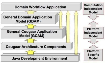
Figure 1 illustrates our approach and its basic MDA concepts pertaining to Cougaar applications. Starting with an often-abstract Computation Independent Model (CIM) such as a process workflow or functional descrip-tion, the Platform Independent Model (PIM) is derived through elaborations and map-pings between the original concepts and the PIM renderings. Once the PIM is suffi-ciently refined and sta-ble, the Platform Specific Models (PSM) are derived through further elaborations and re-finements. The PSMs are transformed into operational systems.
The CIM layer is where vernacular specific to the problem domain is defined, constraints are placed on the solution, and specific requirements illumined. Artifacts in the CIM layer focus largely on the system requirements and their environment to provide appropriate vocabulary and context (e.g., domain models, use case models, con-ceptual classes). The CIM layer contains no process-ing or implementation details. Instead, it conveys non-functional requirements such as business constraints, de-ployment constraints, and performance constraints as well as functional constraints.
Figure 1. Conceptual Cougaar Model Framework
plan, but not the execution of the plan in a tangible form. Beyond high-level services, the problem domain itself must be modeled from a processing per-spective. The PIM is where the logical components of the system, their behaviors, and interactions are modeled. PIM artifacts focus on modeling what the system should do from an external or logical perspec-tive. Structural and semantic information on the types of components and their interac-tions (e.g., design classes, inter-action and state diagrams) are rendered in UML, the defacto modeling language for MDA.
Mapping from the PIM to the PSM, is a critical el-ement of MDAs approach. Mappings from PIM repre-sentations to those that implement the features or func-tions directly in the platform specific technologies are the delineation point where there is considerable leverage in MDA. This mapping allows an orderly transition from one platform to another. But the utility does not stop there. Like the PIM, there are opportunities to have layers within the PSM to produce intermediate transformations on the way to the executable system. These models range from detailed behavior models to source code used in con-structing the system.
levels of modeling (we can skip levels).
The remainder of the paper is organized as follows. Section 2 provides an overview of Cougaar and its ca-pabilities. Section 3 describes the new Cougaar MDA framework. Section 4 outlines some of the underlying structures for the transformations. Section 5 provides a brief case study to illustrate the approach. Section 6 pro-vides a discussion of related work and Section 7 con-cludes the paper.
2. C
OUGAARM
ODEL-D
RIVENA
RCHI -TECTURECougaar provides a platform for developing com-plex agent-based applications that can be aware, self-healing, self-preserving and fault-tolerant. Like many so-phisticated software development technologies, the key challenge is the efficient and timely development of these large-scale applications.
Central to this research effort is an effective technol-ogy for developing agent-based systems well-suited for tasking and workflow common in today’s business en-vironment. Cougaar is an open-source, Java-based tributed agent architecture for developing large-scale dis-tributed agent-based applications characterized by hierar-chical task decompositions [2, 3]. The Cougaar environ-ment enables developers to construct collaborative, agent-based applications that involve high-level tasking, deter-mine suitable processes and activities, and allocate ap-propriate resources to complete the tasking. From an in-formation systems workflow perspective, Cougaar agents collaboratively accomplish various tasks based on the functional business processes with which they are con-figured [8].
Cougaar has been used for rapid, large scale, dis-tributed logistics planning and conclusive research has been performed for fault tolerance, scalability, and secu-rity for enhancing the survivability of distributed agent-based systems operating in changing environments. A Cougaar agent consists primarily of a blackboard and a set of plugins. The blackboard is a container of objects that follows publish/subscribe semantics. The agent is characterized by one or more plugins that are referentially uncoupled (i.e., they do not know about each other). Plu-gins implement the core business logic associated with the agent. They publish objects, remove objects, publish changes to existing objects via the blackboard, or create subscriptions to be notified when objects are added, re-moved or changed in the blackboard.
While agents collaborate with other agents, they do not send messages directly to each other. Instead, a con-cept of task is used for this purpose. Each task creates an “information channel” used within the society for passing
down requirements, and responses going back [2]. Then the agent must be located to allocate the task by creating a subscription that examines the roles or property groups of organizations in the local blackboard. Once the proper organization is found, the task containing the object to be sent to the other agent is allocated to that organization by creating an allocation and publishing it to the blackboard. The Cougaar communication infrastructure then ensures that the task is sent to the specified organization’s and the specified agent’s blackboard. Details of this are presented later in the illustrative case study.
2.1. CMDA FRAMEWORK
Cougaar provides a higher level of abstraction than the underlying Java in which it is implemented. Con-sequently, the conceptual distance between the design abstractions and the source code is somewhat reduced. However, the gap between a domain model (needs and requirements) and a design model is still substantial and the MDA approach is used to bridge that distance and fa-cilitate automatic generation of executable applications.
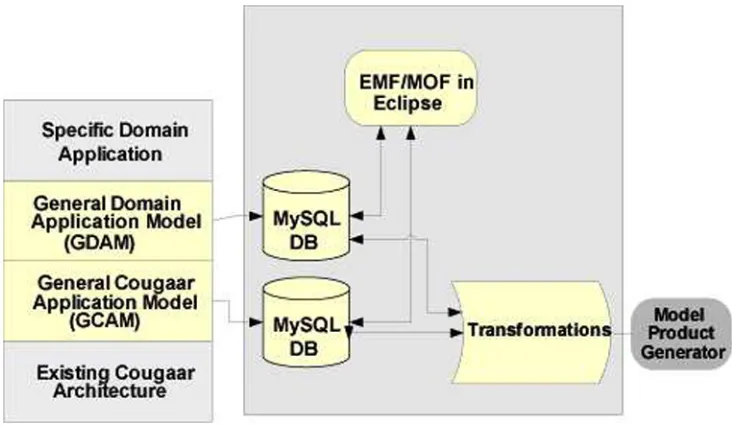
We use a framework based on the Cougaar Model-Driven Architecture (CMDA),to describe the automatic application generation [14, 15]. CMDA prescribes the kinds of models to be used, how those models may be prepared, and relationships between the various kinds of models. Building on Figure 1, Figure 2 illustrates the CMDA framework and exposing its key elements more concretely.
The Cougaar platform-specific architecture models are expressed in the General Cougaar Application Model (GCAM) [2]. The GCAM provides representation in its model of the basic constructs of Cougaar [3]. The core representation includes: Agents, Communities, Societies, Plugins, Assets, Preferences, Knowledge Rules, Poli-cies, Rules, Constraints, Events, Facts, Services, Service Providers, Tasks, Nodes, Subscriptions, Predicate, Mes-sages, Directives, Logic Providers, Hosts, Domains, and Configuration. Beneath these are are the Java and lower-level constructs relevant to the implementation platform.
fol-Figure 2. Model Driven Architecture Framework
lowing decisions were made:
• Transformations between the CIM and PIM should be lightweight. The platform independent trans-formations should subsume the computationally-independent ones thus requiring only a simple trans-formation between the two.
• The business logic must be embedded within the computationally-independent representation to en-force constraints. The constraint language must be simple and easily transformed into code that can be integrated within the platform.
• The platform-specific elements of application con-figuration and deployment are treated separately from the application requirements.
• User interactions and the user interface represent a separate and important challenge. Automatic or semi-automatic user interface generation based on the application requirements is not unique; i.e., there can be many different user interface designs. Such designs can be customized based on the domain pref-erences. We chose to leave this area to our research partners as part of their scope and it is not reported in this research.
3. O
VERALLA
PPROACHIn this section we outline the overall approach to CMDA and detail some key elements that make it effec-tive. At the core of the CMDA is the metamodel that de-fines how components are defined and how they are
al-lowed to interconnect. The components are stored within a database repository, which can be queried by a compiler and an editor. Transforms and mappings are the glue in MDA holding together what would otherwise be an soft-ware artifact reuse approach. These connections offer a key architecture element for the relating of models and concepts.
3.1. TRANSFORMATION
For this research effort, capabilities of various formal methods were evaluated by conducting an in-depth sur-vey of some of the key formal methods used for speci-fying agent-based systems. Formal methods were con-sidered based on their Object-Oriented (OO) modeling support, usability, tool support and concurrency support. Support for representing objects was a key selection cri-terion, as Cougaar is an object-oriented system and in-cludes the ability to represent objects and their constraints such as pre-conditions and post-conditions. Interoperable tool support was another important criterion for selection since CMDA was to be interfaced with the Eclipse plat-form [13]. Tool support also includes GUI interfaces to perform consistency checks, type checking and code gen-eration.
com-pletely and correctly.
The transformation challenges entail using multiple representations to represent the CDMA system compo-nents [8]. The CMDA project endeavors to build a de-veloper environment that offer dede-velopers’ components which can be aggregated to represent the system in the workflow, GDAM and GCAM levels. Each of the com-ponents, named as Workflow Beans, GDAM Beans and Cougaar Beans, respectively, (similar to the Java beans concept) contain sections of software artifacts and related information pertaining to that bean. Some example sec-tions of the software artifacts that beans contain include:
1. The model from which the transformer gleans the partial set of requirements,
2. The model from which the system’s design model is assembled by the transformer,
3. References to the lower-level beans, or links to Java code which can implement the bean (these are tra-versed by the transformer while assembling the sys-tem’s components), and
4. Test case fragments that contain information on how to assembly the unit test cases for the beans.
Further, the bean contains documentation information such as a description of the bean, and constraints pertain-ing to data, operation and connections with other beans. Constraints may be divided into two groups:
1. Port constraints, detailing constraints on input ports of the bean, and
2. Role constraints, detailing the restrictions the bean has on the roles or services the bean provides or sup-ports.
The contents and size of the sections and information in a bean are influenced by the abstract layer to which the bean belongs. The model sections of each bean are rep-resented using the Unified Modeling Language (UML) [21], while the VDM++ or the Object Constraint Lan-guage (OCL) representations may be used to delineate connector and other constraint information. The code sec-tion contain links to Java code libraries at the GCAM level and pointers to lower levels in the rest of the abstrac-tion layers. The requirements might be a combinaabstrac-tion of XPDL, text, and UML diagrams, while the constraints also contain mapping (or connection) information that are mostly rule-based with some formalizations applied.
The workflow of the CMDA system proceeds with the developer assembling the system by picking the right workflow bean components and connecting them to repre-sent the workflow. Constraints pertaining to connections are encoded in the beans. When developers attempt to
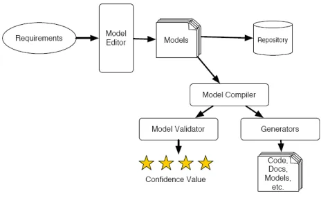
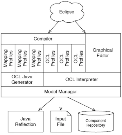
Figure 3. System overview
connect components illegitimately, they are shown a de-tailed error message. Once the workflow of the system is built, it can be verified for consistency. Figure 3 shows the system overview with its respective major elements.
The developer is then shown a list of GDAM beans that can be chosen to map a particular workflow bean. The system will list only related GDAM beans based on the constraints specified by the developer at the workflow level. The rationale to allow developers to choose the right component is to allow developers to make design decisions with the system assisting them (by showing a list of possible solutions and patterns).
Similarly, GDAM beans are mapped into Cougaar beans. In all layers, as and when required, the developer will input the necessary information to satisfy the com-pleteness and correctness of the bean component. The usability of the system can be improved by developing wrappers that would mask the semantic complexities of the representation language. Once the models are built, the transformation engine will traverse through the beans at each level and generate the software artifacts based on predefined transformation rules.
Figure 4. CMDA System Representation
described in detail in the subsequent sections, a quick de-scription is given below to provide an overview of the sys-tem. The CMDA system is comprised of the following key parts:
Graphical Editor: allows the creation and editing of the system description. It allows a mouse-based graphi-cal environment for system specification, tied to the OCL sub-system for full specification and interactive validation. The domain and application models of the intended system are created using the editor. The models are assembled from the components avail-able in the component repository. The editor also fa-cilitates users (Cougaar developers) to create a new domain and new Cougaar components.
Component Repository: is comprised of a database that is used to store components and their revisions. The repository has support for version control in order to facilitate smoother distributed collaborative develop-ment and publishing of components. The repository can be extended using policies and procedures to en-force effective knowledge management.
Model Manager: provides a unified view of all the com-ponents and their contents, either as a Java class vis-ible to the Virtual Machine (VM) via reflection, to the repository, or in the file being processed. The intended system’s design documentation can be gen-erated from the information provided by the model manager.
OCL Interpreter: built on top of ANTLR [20]. The
in-terpreter provides validation of constraints that are defined in the component definitions and supports the evaluation of domain-level and application-level constraints that are used to describe the behavior of the intended system.
OCL Java Generator: used to generate Java source code equivalent to the OCL constraints described by the user.
A Compiler: is a translator that converts, with the help of the mapping and OCL profiles, the input high-level description of the intended system into it is equivalent software artifacts such as Java source code, test cases, and documentation (requirements and design).
Mapping Profile: a translator that takes a configured component description and produces an artifact, such as Java source code or documentation.
OCL Profile: a translator taking a configured component and producing OCL expressions to be used by the OCL interpreter.
3.2. METAMODEL
The Cougaar development process was divided into two modeling phases. The completion of these two phases results in creating domain and application models of the intended system.
GDAM can be conceptually thought of as being sim-ilar to various programming language libraries such as MFC or Swing. The libraries abstract and modularize the commonly-used functions, thereby helping users to focus on encoding business logic. The GDAM can also be viewed as a layer that roughly corresponds to the Plat-form Independent Model (PIM) in the MDA. The PIM is used to represent the system’s business functionality without including any technical aspects. The MDA ap-proach advocates converting PIM models into Platform-Specific Models (PSMs) through a series of transforma-tions, where the PIM is iteratively made more platform specific, ending in the PSM. Hence, GDAM allows do-main experts to represent the specification of the sys-tem in a platform-independent, domain-specific language that can be transformed, without losing information, into specifications of how applications will be implemented in the Cougaar platform.
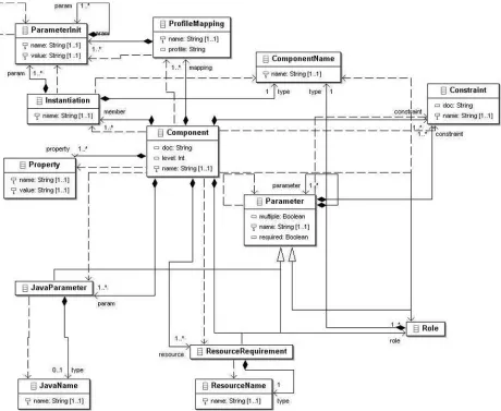
Figure 5. Metamodel
based on templates. That allows a user-developed appli-cation model to be converted into software artifacts based on pre-defined templates.
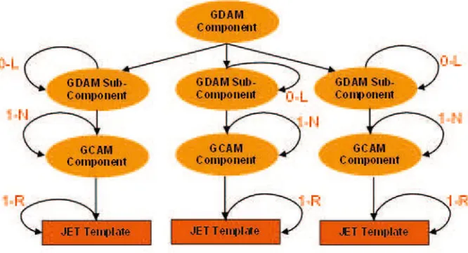
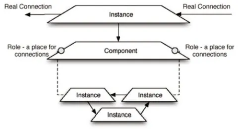
The meta-model of the CMDA system supports the definition of GDAM and GCAM. In order to have a smooth translation between GDAM and GCAM, and to facilitate multiple sub-layers within the two models, the same meta-model was used to define both models. The meta-model is recursive in nature and allows users to specify the intended application as a hierarchy of com-ponents as shown in Figure 5.
Each component contains instances of other compo-nents, at same or lower layers, and the components at the lowest level (called leaf components) should be specific enough for generation of the artifacts. The leaf compo-nents are attached to the templates that contain informa-tion on how to process the parameters of the component and generate the required artifacts (Figure 6).
The meta-model simultaneously specifies several parts of the intended system. These include the follow-ing.
File Formats: the meta-model provides an XML schema for how input files are given to the system. The schema is directly used for storing reusable compo-nents, and is indirectly used as the format for anno-tating XML Process Description Language (XPDL) files to specify a deployment-ready generated sys-tem.
Language: as there is a compiler that translates from the input form to multiple artifacts, an input language specification is needed. Whether from a complete reusable component definition or XPDL, the funda-mental structure and relationships of the components
stay the same, specified in the meta-model.
Parsing: the meta-model is automatically generated from an XML schema into an EMF model. That model is then used to automatically generate a set of Java classes representing its entities. EMF provides inbuilt mechanisms for serializing and de-serializing this model to and from XML, as specified by the original schema.
Structural Analysis: the generated de-serialization code validates the XML against the input schema, thereby some structural analysis and error checking is per-formed automatically.
The meta-model continuously evolves as and when functionalities are added to the CMDA system. At present, the meta-model has at its core a small number of entities (Figure 7):
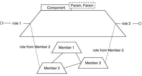
Component: the root element in the hierarchy. It is reusable and specifies the set of parameters that the component takes in when configured as part of the domain or application model. The leaf components (lowest level component) names a Mapping Profile that is used to generate artifacts based on the param-eters specified in the leaf component during compi-lation.
Instantiation: a reference or instance of a component that combined with values for its parameters (Param-eterInits) represents a part of the model. Instantia-tions are contained within components themselves.
Figure 6. A Component
required, multiple, and singular values. Parameters have constraints expressed over them, specified in OCL, that validate values assigned to them.
Role: a type of parameter that specifies another instan-tiation. It is used for representing the connections between components.
Resource: a type of parameter that is used to specify deployment-specific values.
ParameterInit: the value for a parameter. The value can include subtypes of parameter, such as a role or re-source. These are OCL expressions that result in a relevant value. The results of these OCL expressions are passed to the constraints of the original parame-ter in order to validate it.
Property: is a named OCL expression indicating some calculated value relevant to the component. This is used for validation, and provides a level of encapsu-lation around the mechanics of a component’s usage.
Components are allowed to have named parameters to specify them. Unlike simple template parameters, the pa-rameter definitions are defined like a very small subset of an XML schema. Parameters do not define their own tag names, but they do specify anameattribute, which is matched when given a value. They are also allowed to define a parent parameter, thus allowing sets of parame-ters and a cardinality. Together these two allow variable numbers of sets of parameters, giving a reasonable con-figuration language for components.
Components can specify roles, named interconnec-tions, with other components. These interconnections specify data types sent and received over them. Roles are considered special types of parameters which are care-fully initialized only with references to other component instances. They also cannot have inner roles, or any such hierarchy, as normal parameters can.
Similar to roles, deployment data is considered a spe-cial type of parameter that cannot be made hierarchical. In addition, deployment data cannot be given a true fixed-value in a component definition, only an expression us-able for deriving the value when the system is deployed.
Components can specify inner member components that define their inner structure. These member compo-nents are initialized and connected together. Their param-eters, connections, and deployment information are given static values or Object Query Language [23] expressions based on the component’s parameter data. This allows the component to fix some parameters, while simply propa-gating down values for others.
Component properties relevant to the user are exposed through a set of properties, defined as name-value pairs. Each value is expressed using OCL. They can be either OCL constants or expressions that allow their derivation. This allows the component to define its properties as the values of properties in its member components, possibly with some modification (such as unit conversion) and re-naming (to make it domain–relevant).
Unlike parameters, properties don’t take values from their container; instead, they derive values from their pa-rameters, members, or explicit initialization.
While the definitions immediately provide useful de-scriptions of the system, they do not directly provide Java code, test cases, requirements documentation, or UML di-agrams. That is the job of a compiler. The compiler, in some cases, needs “help” from the component definitions.
Figure 7. Metamodel UML Diagram
3.3. COMPILER
The compiler simply acts as a driver for the mapping and OCL profiles. Given a top-level component defini-tion, it executes some of its own static validation checks, followed by the component?s constraints, followed by the execution of any mapping profiles. The component’s con-straints may call OCL profiles as needed. Once the com-piler finishes this process for the top-level component, it proceeds through a depth-first traversal of the com-ponent’s instantiations, repeating the process described above. At the end, the components have all been validated and have had artifacts generated from them. The compiler is an Eclipse builder, watching for changes to files within a project configured to use it. When a file with an ex-tension of.Xcompis modified, the compiler invokes a full rebuild. Through interaction with the Implementa-tion Repository, it minimizes work for instantiaImplementa-tions that haven’t changed.
Mapping profiles provide the mechanism for
generat-ing artifacts from an instantiation. They extend an Eclipse extension point defined by the compiler, and implement a specified interface that generates an artifact when given an instantiation. An additional wrapper is provided that allows Java Emitter Templates (JET) to be used, by ex-tending a second extension point instead. The compiler scans for and detects either type of extension, and maps its fully-qualified id attribute as its name. When an instan-tiation’s component lists this name, the mapping profile is invoked to generate text for an artifact.
As each instantiation can generate artifacts, those arti-facts must be created and managed. By properly manag-ing them, we can avoid wasteful regeneration of artifacts on unchanged components. The instantiation repository manages the contents of the dependent project. It creates one directory underneath the project for each component, named after it. Underneath that, it creates a numbered di-rectory to contain each instantiation. The mappings of in-stantiation parameters to these directory numbers is man-aged via an XML file that stores the mappings as the in-stantiations are generated. The dependent project has an Eclipse nature that maps to a class that provides methods for accessing and manipulating the instantiations avail-able in the repository.
The model manager provides a unified name space for the OCL interpreter, combining multiple sources of potential data. The default sources are straight-forward: the input file, allowing self-referencing; Java reflection, allowing references to Java types like
java.lang.String and the component repository, allowing references to components other than the one cur-rently being defined. It should be noted that the details of the model manager’s interfaces won’t be complete un-til it is tested against the OCL interpreter and generator’s needs. The input file’s component is simply wrapped to an instance called self. That variable is required for ba-sic operation. Using standard reflection mechanisms un-derjava.lang.reflect, a complete interface is pro-vided to the entire Java type system and all types avail-able to the plugin?s classpath, as determined by Eclipse’s management facilities. The component repository offers an interface to the model manager, to allow components to refer to others.
3.4. JET TEMPLATE
The CMDA system works on two key sub-elements: the meta-model and JET templates. The meta-model is the base for building domain and application models that are used to specify the input parameters of the intended Cougaar application. The data captured in the models (GDAM and GCAM) are serialized into an XML docu-ment. The XML document referred to as .Xcompfile shows the “design” of the intended system..Xcompfiles are a serialized XML version of the EMF model used to represent the CMDA model. They are used as the input to the JET templates to produce the code. The deployment parameters are separate issues and the.Xcompfile does not contain any deployment parameters.
The structure of the models can be considered as a typical tree or graph with nodes representing the com-ponents, and the edges between nodes representing the linkage between components. The linkage between the components can be of two types: inter-layer and intra-layer. The intra-layer linkage represents the connection
between two components residing in the same layer and the inter-layer linkage represents the composed of rela-tionship between a component and its lower-layer compo-nents. The components in the upper layer have to be com-posed of components residing in the lower layers. The components in the lowest layer (leaf nodes) are attached to JET templates through means of profile mapping. The profile mapping specifies which JET template needs to be used for converting the parameters into artifacts.
The JET template is the template file written with a JSP-like syntax (actually a subset of the JSP syntax). It can not only express the source code that needs to be gen-erated, but also other software artifacts such as documen-tation. Like the general JET template, the Cougaar JET template mainly consists of two parts: the static part and the dynamic part. In order to maintain the modularity and reduce the file size of JET templates, the developer can fragment the JET template into multiple files. The break-ing of the JET templates will also help in reusbreak-ing the tem-plate fragments. The breaking process is achieved by cre-ating a new JET template, crecre-ating an object of the tem-plate, and invoking the generate method. The attributes required by the template fragment are passed as param-eters of the generate method. A number of ready-made templates were created for the CMDA system.
3.5. COMPONENTDEVELOPMENT
The CMDA system requires a set of domain and ap-plication components to build the model and to generate software artifacts of the intended system. The compo-nent development is an evolutionary process and any pre-existing source code can be wrapped with the minimum effort and used in the CMDA system. This is to ensure that least amount of startup time is spend on using a pre-existing code as a new component. While a new compo-nent can be created easily from pre-existing source code, the reusability of such component is very limited as these components have very little or no parameters. As and when the new component, created for a specific instance, needs to be reused, the JET template for the component is refactored and parameterized. After a series of such evo-lutions, the JET template is highly parameterized and that component becomes highly reusable.
The number and reusability of the components in-crease along with the inin-crease of usage of the CMDA sys-tem. In order to start the evolution of the components, a set of seed components was developed. The set of seed components developed includes:
Expander: a highly parameterized component that will generateExpanderPlugincode.
in-stances where no new task is published by the plu-gin.
AllocatorwithTaskPublish: a component with low pa-rameterization that will generate AllocatorPlugin
code for some instances in which a new task is pub-lished into the blackboard.
Assessor: a component with low parameterization that will generateAssessorPlugincode for some specific instances.
Completion: a highly parameterized component that will generate code for a generic Plugin that sub-scribes to a task and masks it as complete.
Execution: a highly parameterized component that will generate code for theExecutionPlugin.
Aggregator: a highly non-parameterized component that will generate the code forAggregatorPluginfor very specific instances.
3.6. DEVELOPMENTENVIRONMENT
The Meta-Model is based on a few simple concepts:
• Collaboration Components are designed to work to-gether to finish a task. They interconnect via con-nection points called “Roles.”
• Decomposition Components can be defined in terms of other components. Each use of another compo-nent is called an “Instantiation.” The inner definition itself can be a network of collaborating components. This and the collaborative concept above make the Meta-Model recursive (Figure 8).
• Reuse Components are designed to be used multi-ple times. However, each time its used, a component must take parameters that define its specific behav-ior. An Instantiation of a component contains values to fill those parameters, called “ParameterInits.”
• Generation The Component definitions by them-selves aren’t the desired end-product. Instead, com-ponents define (or reference) definitions of how ar-tifacts source code, UML models, documentation, deployment information, etc. are generated from a component definition. These definitions are called “Profile Mappings.” Profile Mappings interpret a component instance’s parameter values to determine how to generate the appropriate artifacts.
• Validation As the assemblies of models are expected to be complex, some automatic ability to verify the correctness of them is desirable.
CCollaboration omponents were designed to work to-gether. The workflow as imported into the system is a flowgraph representing the stages and decisions of the de-sired application. At the top level, this represents com-munities of Cougaar agents collaborating. Due to the re-cursive nature of the Meta-Model (described below), in-dividual agents or even inin-dividual plugins collaborations can be described using the same mechanisms. Collabora-tion between components is primary described using con-nections between Roles. A Role is simply an endpoint for a connection, declared and attached to a Component. An Instance of the component is connected via its ports to other instances, forming a graph.
CDecomposition omponents can be defined as its own graph of other component instances . This allows the CMDA system to use the same tools, Meta-Model, and user interface for society, agent, and plugin-level descrip-tions. Similarly, entire systems can be converted into reusable components for larger systems later.
EParameterization ach component declares what kind of parameters it needs in order validate and generate arti-facts. The parameter system in CMDA is fairly complex, so a slow, thorough approach will be taken in its descrip-tion.
The “Parameter” is an abstract input to a component, like a Java Interface or C++ abstract class. A component actually takes in:
1. Roles Names of other component instances that the generated instance will collaborate with.
2. JavaParameters A Java object value (as a string). Described in detail below.
3. ResourceRequirements A parameter that is only needed for deployment. These should be OCL ex-pressions that are evaluated at deployment time to determine their final values.
Figure 8. Component structure
OGeneration nce validated, a component instance is passed to its profile mappings (PMs). Profile mappings are compiler extensions that generate artifacts. A compo-nent specifies which profile mappings apply to it. Each PM generates output, possibly with its own internal val-idation system, capable of declaring errors on the input .xcomp file, viewable as normal compile errors. How-ever, those validation failures are internal to the PM and do not cause a full-level validation failure.
4. T
RANSFORMATIONR
ULESGiven the metamodel, we can now describe our trans-formation approach in some more detail. Our transforma-tions have three primary stages:
1. Tree Decomposition — The top–level model is treated as a single component. The component serves as the root of a component tree that contains the entire system being generated. The tree structure prevents cyclic dependencies, stratifies the compo-nent graph into layers, and provides a deterministic execution path for the generation of the system.
2. OCL Evaluation— Parameters to each component are evaluated as OCL expressions before use (includ-ing their connections to other components). OCL supports the UML models, and serves as an expres-sive means to transform semantics between layers of the system.
3. Artifact Generation— When the final artifacts are needed, an expressive Java–based runtime is fully accessible to generators to create artifacts in any way they deem necessary. The system invokes generators with their parameters and provides them with full ac-cess to the system being generatedandthe Cougaar CMDA runtime.
4.1. TREEDECOMPOSITION
All models are structured as simple trees. Each layer jump between platforms: the platform–independent model, the platform–specific model, etc., reify as levels in the tree’s hierarchy.
4.1.1. Component Layering: Transformations occur at the boundaries of the CIM, PIM, and PSM. Even within these layers, there are often many transformations. Trivial transformations are handled in a single level, while non-trivial transforms may take several levels to fully resolve. Abstractly, platform dependent and independent can be represented by two adjacent layers, but complex systems and platforms usually require many layers of transforma-tion before the full system can be specified. If the under-lying platform is hierarchal, we can directly map compo-nents to the underlying platform, leading to a straightfor-ward transformation.
If the platform is distinctly different, we may define a single child for a component, which converts semantics between the platform independent and dependent layers. After it has done its internal transformations, it can then contain additional layers of children to continue the trans-formation.
Even further, if this transformation procedure isn’t ap-propriate for a particular part of the platform, the compo-nent can define a mapping to do the rest of the work. The mapping can then execute its own procedure for further transformation and artifact generation.
The component developer may choose this route for a few reasons:
artifact already generated anywhere else in the sys-tem, they may choose to reuse it with differing in-stantiation parameters.
2. Refactoring— Like traditional compilers, some lev-els of automatic refactoring may be implemented. Common subcomponents could be factored out and reused in several places. In CMDA terms, utility plu-gins could be dropped in for common combinations of other plugins, resulting in much smaller and faster object code.
3. Nonhierarchal Processing — Some platforms may simply not be amenable to hierarchal decomposition. Whatever methods are best for them can be placed in, instead of attempting to coerce it back into a tree.
Even in this case, the complexity is hidden behind a single component. It has its parameters to use as it needs, and through their evaluation, access to the entire contain-ing component’s definition — via theself.parent pa-rameter provided by the system.
As such an escape from the hierarchal system is still represented as a regular component (with a different map-ping), it is compatible with the regular CMDA system above and below it. Regular CMDA components can in-clude it as needed, without any concern for its internal structure. Similarly, this non-traditional component may only choose to do part of its work nonhierarchially. It can still include other CMDA components that do use the regular execution and generation path.
4.1.2. Execution Path: The system’s generation path executes in a top–down–top pattern. Top–down, the OCL parameters and constraints are evaluated, and validators run. With a valid system defined, and the parameters’ final values evaluated, we find ourselves at the leaves of our system’s defining tree. There, we execute our artifact generators for the leaves.
We continue bottom–up. With these leaf artifacts gen-erated, we return an identifier for the artifact back to the parent. The parent’s generator is run, with all its child artifacts’ identifiers available. We proceed back up the tree this way until we have the topmost artifact generated, resulting in a complete system.
4.2. OCL EVALUATION
OCL makes for a very natural parametric language for the CMDA system. First, it comes with UML. Second, it provides a good expression language for describing pa-rameters. Third, it is effectively for building quick valida-tion passes through the declaravalida-tion of simple constraints. We use OCL heavily in the system. While we use the tree–level decomposition to break down our layers be-tween the PIM and PSM, OCL wires it all together.
Par-ents specify OCL expressions to configure their children. Beyond normal numeric, string, and boolean expressions, we can supply Sets, OrderedSets, Bags, and Sequences1.
When the CMDA system executes to generate arti-facts, we run OCL expressions in three different parts of the component:
1. Parameters — OCL expressions that evaluate to scalar values, strings, and various collections.
2. Roles— References to siblings or parent–level enti-ties in the platform. Roles connect components to-gether.
3. Constraints— OCL predicates validating the result-ing values of the parameters and roles.
Parameters can configure any aspect of a component. Each parameter’s definition includes the method it’s in-terpreted with. Some will be OCL expressions, some are simple strings, and others are run–time OCL expressions. In Cougaar, we can configure static attributes resulting from expressions. We can also define OCL expressions that pass on verbatim to generators, which set up the OCL for execution at run time.
Siblings connect to each other through roles, which specify collaborators through OCL expressions like
self.parent.other-sibling. In Cougaar, this includes other agents in a society.
4.3. ARTIFACTGENERATION
Generators are keyed to different profiles, such as source code, documentation, or formal models. Each gen-erator connects to a component through amapping, which is invoked during the CMDA compiler’s execution. Gen-erators have full access to the parameter values of the component, and are allowed to generate a single top–level artifact for that component. The nature of the hierarchy for artifacts depends on the artifact generated (e.g. a Java artifact generator may only return one class name to the parent).
They may, however generate multiple inner artifacts. For example, instead of a single Java class, an entire pack-age may be generated, following a naming convention de-fined by the coordination of generators between a parent and child component.
In the next section, we discuss an abbreviated case study that outline how the transformations are imple-mented and used to generate Cougaar applications.
5. S
UMMARYC
ASES
TUDYIn order to get a more concrete sense of the CMDA approach and the prototype environment that was
oped to explore key aspects of the approach, this section provides an abbreviated case study. The feasibility of the overall approach and representation mechanism was evaluated by developing a workflow model for a sample project, namely Books OnLine 2 [1], a complete exam-ple of a Cougaar-centric application. BooksOnLine em-ulates functionality of an online book store and incorpo-rates many of the infrastructure features.
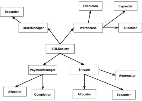
Figure 9 illustrates the basic elements of an online book store where each circle is a cluster within a Cougaar society of collaborating agents. Each of these organi-zations will have several different subfunctions imple-mented using Cougaar PlugIn components.
Figure 9. Books Online Example [1]
As an example, Figure 10 shows P ayment cluster that includes functionality that will be used by a company outside of the corporate boundaries of BooksOnLine.
Figure 10. Payment cluster [1]
Figure 9 shows the overall structure of interaction be-tween the agents. At the top level, the interaction is de-fined through the roles each agent defines for collabora-tors and the assignments of these roles. Looking at Fig-ure 11, we see that we have a 3–level hierarchy of artifacts to generate.
At each level of the hierarchy, a different set of gen-erators are defined to analyze the model and generate rel-evant artifacts. At the bottom–most layer we have our Expander, Execution, Allocator, Aggregator, and Com-pletion models. Generators at this level generate directly executable code for the Cougaar API, and correspond 1-1 to each of these models. For example, we have an Ex-panderGenerator that analyzes instances of Expander in models and generates Java code that implements the Ex-pander design pattern.
The models have parametric values which the genera-tors read and use for code generation. In Figure 11, there would be several different Java source files generated by the Expander’s generator. The generated Java code is in the form of Cougaar plugins, connecting directly into its existing infrastructure as if it was hand–written. Each Java class would be similar in structure to each other, but would have specific differences that cause them to operate in line with their parameters. These Cougaar-API level PSM models are typically implemented using a fill–in– the–blank JET template system, which work similarly to the well–known JSP (Java Servlet Page) system. The ma-jority of the generated code is written verbatim in the tem-plate, with generation logic defined as Java code within a block of escaped text.
Parameters transform through two paths. First, com-ponents define expressions for their inner comcom-ponents, based their own parameters. As these expressions are OCL, they can be rather sophisticated. The dependency graph for parameters is top–down. Each component de-fines input parameters that it uses to determine the values for parameters passed to its inner components. The gen-eration process thusly goes top–down to evaluate all the parameters. At the bottom–most level, the values of all parameters have been fully evaluated, and artifacts can be generated. The top–most component cannot define any input parameters.
Second, the generators take the resulting parameters and use them for their own artifact generation. The OCL interpreter is available as a library both at generation time and at runtime for the generated artifacts. In the lat-ter case, the OCL is compiled at program initialization. OCL–aware components have been written to simplify. The loop below uses the numOfSubscriptions pa-rameter as a count for a loop, generating several subscrip-tions as needed.
files that instantiate the generated Java–based plugins. The agent.xml files use the Cougaar infrastructure for loading our generated Java code. The generator applied to all four of these agents is the same, a JET template that generates the agent.xml file.
Finally, a generator is run against the BOLSociety model, which generates an agent.xml file. Similar to the JET template for agent.xml, it simply generates a soci-ety.xml file. Both of these files are defined by two differ-ent schema in the Cougaar architecture.
As discussed earlier, the overall generation process occurs top-down. When we run against the top model, it invokes a build against all of its sub–models. The sub– models do the same, recursively. At the bottom level, the generators take their evaluated parameters and generate Java code for the Cougaar plugins. The generators return the name of their generated artifact up to their parent. The parents then generate their artifacts and return the name of their generated artifact up to their parent.
In the Books Online system, the BOLSociety’s build will invoke a build of all the agents. Like all the other agents, the Warehouse would invoke generators for it’s contents —the Execution, Expander, and Alloca-tor plugins. The plugins’ generaAlloca-tors would return Java class names to the Warehouse’s compiler. The class names would then be used to generate the Warehouse’s agent.xml. The Warehouse’s agent name would be re-turned to BOLSociety’s build, which would then use it in it’s society.xml
At each level, we use Cougaar’s standard methodol-ogy for parameterization. At some levels, the child ends up being responsible for generating its fully–configured self. At others, the parent will instantiate and configure the child at run–time. When a parent configures a child, the parent stores the child’s parameters in it’s artifact. When a component is responsible for it’s own parame-ters, the generated artifact uses the parameters directly. For example, some parameters to the Expander will result in specific piece of code being generated. Other param-eters will result in text being generated in the agent.xml, which the Cougaar runtime will use to configure our Ex-pander plugin at runtime.
As the generators defined at each level can be JET templates (any eclipse plugin extending our APIs can be generators), we can start each one from a hand–written artifact. The original artifact is simply renamed to indi-cate it’s now a template (.javajet), and the model will specify it as a generator. The generator developer then starts defining parameters and its accompanying genera-tion logic to generalize the template.
At the top layer, we have a simple container model that holds the components and wires them together:
<?xml version="1.0" encoding="ASCII"?>
<model:component xmlns:model="http://www.cougaar.org/xc/model" doc="" level="0" name="BOLSociety">
<member name="TheWarehouse"> <type name="Warehouse"/>
<param name="bookSupplier" value="OrderManager"/> <param name="superior" value="OrderManager"/> </member>
<member name="TheOrderManager"> <type name="OrderManager"/> ...
<mapping name="Cougaar11" profile="gcam.jet.Society"/> </model:component>
Using themappingtag, we indicate which generator will create an artifact for this model. Multiple generators may be specified, creating mulitple models. We specify anOrderManagerfor both thebookSupplierand
superiorroles here. The Order Manager is instantiated below that. While our simple example only requires one of each, the same agent could have multiple instantiations, with different parameters to specify each.
Below that, we have model definitions for every type of object Here, the Warehouse would define itself as two plugins within an agent.
<?xml version="1.0" encoding="ASCII"?>
<model:component xmlns:model="http://www.cougaar.org/xc/model" name="Warehouse">
<member name="WarehouseExecution"> <type name="Execution" />
<param name="subscription" value="o.isKindOf(Task) & & o.oclAsType(Task).getVerb()=’PACKER’"> <param name="variable" value="PerformJob_performJob">
<param name="contents" value="new PerformJob(getBlackboardService(),
task, logging, getPlanningFactory())" /> </param>
<param name="CodeSnipet"
value="threadService.schedule(performJob, 1000);" /> </param>
</member>
<member name="WarehouseExpander"> <type name="Expander" />
<param name="subscription" value="o.isKindOf(Task) & & o.oclAsType(Task).getVerb()=’BOOKSFROMWAREHOUSE’"> ...
The Warehouse is made of two plugins within the Cougaar agent: an ExecutionPlugin and an
ExpanderPlugin. The first is a simple plugin that accepts Java code in some of its parameters.The
subscriptionparameter provides the plugin with an OCL expression to look for on the Cougaar Blackboard. Upon finding an object of this type, it declares a vari-ableperformJob of typePerformJob2. The vari-able is filled with a newPerformJobinstance, initial-ized to the current task. The current task is defined by the
ExecutionPlugin. Once filled, the variable is used in a direct piece of java code fed in throughCodeSnipet.
threadServiceis defined as a standard member vari-able of the plugin.
ExecutionPlugindefines itself quite simply as an XML schema:
2Direct Java code in the parameters are a “backdoor” to allow generator
<?xml version="1.0" encoding="ASCII"?>
<model:component xmlns:xsi="http://www.w3.org/2001/XMLSchema-instance" xmlns:model="http://www.cougaar.org/xc/model" doc="" level="0" name="Execution">
<param name="subscription">
<parameter xsi:type="model:javaParameter" name="variable"> <parameter xsi:type="model:javaParameter" name="contents"/> </parameter>
<parameter xsi:type="model:javaParameter" name="CodeSnipet"/> </param>
<mapping name="ObjectName"
profile="org.cougaar.xc.pm.demo.ExecutionPlugin"/> </model:component>
A simple subscription containing variable
andCodeSnipets,
An abbreviated look at the template will be useful:
<%@ jet
class="ExecutionPlugin" ...
import java.util.*;
/**
* ExpanderPlugin with parameters <%= argblock.getInst().getParam() %> */
public class <%=className%> extends BOLComponentPlugin { private static final String pluginName = "<%=className%>"; private ThreadService threadService = null;
// NAME = <%= Interpreter.eval (argblock.getInst(), "self.type.name")%> <% ArrayList subs = argblock.paramsNamed ("subscription");
ArrayList names = new ArrayList (subs.size ()); ArrayList preds = new ArrayList (subs.size ()); ArrayList exprs = new ArrayList (subs.size ()); int i;
for (i=0; i<subs.size (); i++) { String name = "subscriptionNr"+i; String pred = "predicateNr"+i; names.add(name);
preds.add(pred); %>
private IncrementalSubscription <%=name%>; <% ParameterInit pi = (ParameterInit) subs.get (i);
exprs.add(pi.getValue ()); %> private UnaryPredicate <%=pred%> = new OCLPredicate ("<%= pi.getValue ()%>");
<% } %>
protected void setupSubscriptions() { <% for (i=0; i<subs.size (); i++) { %>
<%=names.get(i)%> = (IncrementalSubscription) getBlackboardService().subscribe(<%=preds.get(i)%>);
<% } %> } ... /**
* Expand as indicated. */
protected void execute() {
System.out.println ("Executing " + pluginName); Enumeration e;
<% for (i=0; i<subs.size (); i++) { %> /*
Check: <%=exprs.get(i)%> */
e = <%=names.get(i)%>.getAddedList (); while (e.hasMoreElements()) {
try {
Task task = (Task) e.nextElement ();
<% ParameterInit sub = (ParameterInit) subs.get(i); EList subE = sub.getParam();
Iterator subI = subE.iterator(); while(subI.hasNext()) {
ParameterInit var = (ParameterInit) subI.next(); if(var.getName().equals("variable")) {
StringTokenizer st = new StringTokenizer(var.getValue(),"_"); String varType = st.nextToken();
String varName = st.nextToken();
ParameterInit contents = DemoUtils.findChild(var,"contents");%> <%=varType%> <%=varName%> = <%=contents.getValue()%>; <% }else if(var.getName().equals("CodeSnipet")) {%> <%=var.getValue()%>
<% } }%> } catch (Throwable t) {
System.out.println (pluginName+": failed on expansion of \"<%=exprs.get(i)%>\"");
} } <% } %> }
}
We demarcate elided parts with
el-lipses. In the class declaration, we define as many IncrementalSubscriptions and
OCLPredicates as we have subscription
parameters. In setupSubscriptions, we initialize
the subscriptions with our predicates on the Blackboard. Finally, inexecute, we go through all of our parame-ters given in eachsubscription, and do the variable declarations and Java code declared in each.
The workflow model was transformed into PSM and code fragments (code for Assets and Agents) were gener-ated from the PSM. This demonstrgener-ated how components are created, assembled (to create application and imple-mentation models) and transformed into design, code and documentation artifacts (Figure 11).
Early on in the effort, there was considerable skepti-cism around the ability to actually generate Cougaar ap-plications from high level specifications. To a large de-gree, this has relaxed as we learned more about MDA and about available tools to support the CMDA prototyp-ing effort. While there is still a healthy respect for the effort needed to generate all of the work products from a Cougaar Application development effort, the gap has closed considerably. We have now seen that for general instances of workflow and agents, parameterized compo-nent specification is a viable option with reasonably good results. There are still instances where complete speci-fication is difficult, requiring human-in-the-loop effort to supply vital information, but they are not overwhelmingly hard or the norm.
Generating source code from increasingly refined and elaborated models was feasible and in most situations doable. The CMDA Meta-Model based on the recursive GDAM/GCAM structures appear to provide a reasonably good framework from which to implement the MDA ap-proach. While the prototype was not robust enough to develop full Cougaar Applications in a development en-vironment, it did develop them in an experimental envi-ronment. We did not examine scale or special cases of developing components; however, for the general cases that we experimented with, there were some promising results.
However, we found that roundtrip engineering re-quires considerable information and closure on that in-formation to be fully feasible. However, a looser interpre-tation of roundtrip engineering based on mappings and dependencies coupled with todays reverse engineering tools provided significant leverage towards the objective. Given our experience, we believe that as the CMDA com-piler evolves, roundtrip engineering for the larger class of components will be feasible. It will require account-ing for component, connections/dependencies, and con-figurations that are expressed in forms like the .Xcomp file we currently employ. Further, there will need to be a more elaborate artifact management approach to sup-port roundtrip engineering in future implementations of CMDA.
Environ-Figure 11. Books Online artifacts
ment (IDE). As it turned out, this worked well for im-plementation. The UML as a base language provided the input while the Design-Generate-Test cycle fell naturally with the bounds of the IDE. Using this approach, the typ-ical compilation issues such as validation, error recovery, name lookup, and the like, show up quickly.
However, it is important to note that unlike traditional source code, different formats are relevant for different levels of abstraction in CMDA. Different diagram formats are relevant for component, agent, and society levels, such as class, component, and package metaphors. Albeit, we found in Java normal source code is perfectly fine at all levels.
Like other MDA efforts, we found that artifact man-agement quickly becomes complex with all the different kinds of artifacts. Moreover, these artifacts were relevant at different times, much more than any nontrivial system can manage at a low level. We found that deciding which artifacts to generate at any given time are best decided through some delegation mechanism. This is the rea-son for the tight integration between the compiler and the component templates (the templates plug into the
com-piler and extend its interfaces) the dependencies could be managed in an automated manner, relieving the developer of the burden.
We found that most artifacts have their own deploy-ment needs (i.e., relative and absolute path locations). For example, java source has to be deployed to match the de-clared package and class name. Naming the artifacts and preventing conflicts in naming is a complex problem to do well. To ensure uniqueness, while we could use an generator to generate new names from scratch (e.g., auto-gener 1), we would sacrifice human comprehensibility of the generated code (as well as the other model artifacts).
From a project management perspective, there were some reasonable lessons learned as well. The design and underlying architecture needs time and patience to evolve in applied research projects like this one. We should not hesitate to improve the design, even midway through the project (provided the changes do not adversely affect the project schedule). This avoids homeostasis of initial de-sign and provides the necessary learning that is an impor-tant part of this type of effort. The willingness to transi-tion to a more aggressive infrastructure was a good move as it resulted in a more flexible solution.
6. R
ELATEDW
ORKThere have been a number of projects that have ad-dressed multi-agent systems (MAS) and MDA before and since our first research effort using this technology back in 2003 [8]. As we investigated more and more de-tailed issues, we found leverage using MDA principles [9]. We targeted a model-based engineering approach flexible enough for many model representations (ranging from abstract requirements to concrete code) to be used. While we engaged the MDA structure (i.e., CIM to PIM to PSM) to separate key development and evolution con-cerns, a distinguishing element of our approach is that we have not stayed strictly with the OMG route of de-riving artifacts mostly in UML. Rather, when UML was the expedient route, it was used. Otherwise, we adopted the notion that if we had a close rendering of the capa-bilities needed in the lower levels and they could be ab-stracted to the higher layer without creating an interoper-ability dependency, then we would build the transforms and mappings directly. For example, when we developed the Expander for flexible tasking (described earlier), it was more expedient to opportunistically map the notion of task in the PIM to the agent tasking components in Cougaar (without violating the PIM and PSM separation). This allowed quick and verifiable transformation rules.
Some non-MDA-based MAS methodologies such as Prometheus [19], Tropos [10] and MaSE [12] have pro-posed the mapping of the design models into implemen-tation code and have provided some tools for supporting both the design and the implementation of MAS. How-ever, it is possible to describe platform specific details during the design of the application — violating the sep-aration of concerns between PIM and PSM. The resulting high-level design models can be platform dependent and, consequently, are not easily portable to any other plat-form.
As with many MDA-oriented MAS efforts, we chose to use a combination XML and other representations like OCL because they lend themselves to the support of transforms and mappings. As described in [5], the
key to MDA lies in the modeling representations and the transforms/mappings. XML lends support for major data transformations while OCL provides the constraints nec-essary to characterize mappings to relevant components and parameters for configurations. CMDA follows a sim-ilar form, but is less UML specific in its representations. Where there exists a line from abstract models to con-crete components (source code is a model), CMDA al-lows the incorporation of the models and relevant trans-forms/mappings.
Other research has used the MDA approach to de-fine a MAS development process. [22] demonstrated the use of MDA to derive MAS low-level models from MAS high-level models. The authors propose to use the Tro-pos methodology and the Malaca models in the MDA approach. The high-level models created while using the Tropos methodology are transformed into low-level Malaca models. However, the transformation from the Tropos models into Malaca models is not completely au-tomated. Since human in the loop is not explicitly de-signed into the approach, there are some discontinuities in the flow when this occurs. Moreover, such an approach does not deal with the transformation from Malaca mod-els into code. In [16], the authors proposed a domain-dependent methodology based on a model-driven ap-proach for the development of distributed mobile agent systems. They define a mobile agent conceptual model for distributed environments and describe a set of com-ponents, represented by a collection of intelligent mobile agents.
Koehler et al. outline their transformation method that implements model-driven transformations between PIM business view elements and PSM architectural models [18]. This approach, while more sophisticated for the boundary between PIM and PSM, maps well onto the CMDA approach. In CMDA, we attempted to stay as sim-ple as possible, but comsim-plex enough to handle the com-plex tasking that could arise with collaborative agents in Cougaar. The CMDA metamodel was derived from our experience and provided a reasonable structure for the rel-evant transformations and mappings.
More recently, Demir compared the Software Factory approach espoused by Microsoft with the Model-Driven approach [11]. While the example with the online book-store (standard example for MASs), lines up nicely with CMDA, the paper is theoretical and is not supported by an actual prototype or empirical results. CMDA does provide a complete system that demonstrates what Demir discusses in his paper with the exception of the compari-son with software factories.
![Figure 9. Books Online Example [1]](https://thumb-us.123doks.com/thumbv2/123dok_us/872579.1584772/15.573.70.265.262.438/figure-books-online-example.webp)