Multi-agent Optimal Control of Ball Balancing on a Mobile
Robot
Amir Mohammad Hosseini
,
*
Adel Akbarimajd
Department of Electrical Engineering, Faculty of Technical Engineering, University of Mohaghegh Ardabili, Ardabil, Iran
1.
Introduction
Distributed artificial intelligence or theory of multi-agent systems have been initiated in computer engineering (see for [1] and [2]), however in recent years they have been applied in many different fields. Multi-agent systems are composed of several interconnected subsystems. From a viewpoint, these subsystems operate autonomously and are controlled independently; thus each of them can be interpreted as an “agent”. From another viewpoint they are components of a large system and they must have interaction and interconnection.
The main characteristic of multi-agent systems is their distributed nature, as they may be spatially or temporally distributed. Due to the advantages in simplicity, fault tolerance and scalability, research on multi-agent systems have been rapidly expanded in recent years and these systems have found interesting applications in multi-robot environments [3]-[6], transportation [7], [8], power networks [9]-[11] and … . Some applications such as multi-robot and transportation systems are innately distributed. However, some other applications such as power networks had been planned and controlled over decades as monolithic systems but in recent years, with some representations, they have been behaved as multi-agent systems.
One of the concepts associated with multi-agent systems is multi-agent control. Due to complexity and bigness of multi-agent systems, it is desired that their controllers is designed and implemented in a distributed manner. That is each controller takes feedback from its local states rather than taking feedback from all states of the system. Here, the main challenge is that the control objectives are essentially defined for the whole system and satisfying global objectives with local information needs innovations in control structure.
In this paper a distributed control scheme is proposed in order to balance a ball on a mobile robot. This work is somehow related to the widespread works done about
control of ball and beam system (see [12] and [13] as two of recent ones). The difference is that the typical ball and beam system is not located on a moving platform. Moreover, no distributed control mechanism is applicable for ball and beam system. The ball balance system proposed in this paper is actually a new platform for design and test of multi-agent control systems. A two-loop distributed optimal control strategy is also provided for the proposed system.
The rest of the paper is organized as follows. In the next section the proposed ball balance system is introduced and its dynamic equations are derived. In the third section, the control task is distributed among two agents and a two-loop optimal control scheme is designed for the each agent. In Section 4 simulation results are provided and finally section 5 includes conclusions and discussions.
2.
System Modeling
The system under study is shown in Figure 1. The base system is a planar mobile robot. A link with length L
Fig. 1. The proposed ball balance mechanism
is located above the robot that is supported by two prismatic joints with joint variables d1 and d2. Prismatic
joints are driven by two electric DC motors, shown by M in the figure. A ball with radius R is located on the link. Mass and moment of inertia of the link and ball are mL,
Abstract: Multi-agent systems have origin in computer engineering. However, they have found applications in different fields. One of the newly emerged problems in multi-agent systems is multi-agent control. In multi-agent control it is desired that the control is done in distributed manner. That is the controller of each agent should be implemented based on local feedback. In this paper a mechanism is introduced as a test bed for multi-agent control systems. The introduced mechanism is balancing of a ball on link located on a planar mobile robot. Dynamic equations of the mechanism are derived and the control task is distributed among two agents. For each agent a two loop controller is designed wherein external loop is a LQR controller and inner loop is a simple proportional controller. Regulation and fault tolerance performance of controller scheme is evaluated by simulations.
L
J , mB and JBrespectively. We denote the distance of
the ball from middle point of the link by r and the angle of the link with horizontal line by α. The goal of the control task is to balance the ball on the link and to keep it in the middle point of the link (r=0, r=0) while the mobile robot is moving.
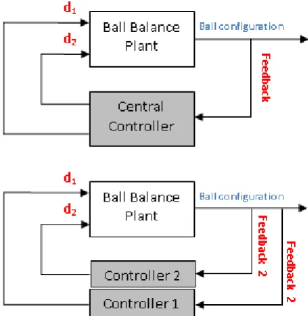
The control objective should be achieved by control of prismatic joints. Here, two control strategies are available: centralized control and distributed control. Schematic of these strategies are shown in Figure 2. In centralized control, a feedback from ball configuration is supplied to a central controller who is responsible for generating appropriate values of d1 and d2 to achieve control objectives. This problem is a multivariable nonlinear control problem which imposes complexities in design and analysis. In distributed control approach however; two independent controllers are implemented for d1 and d2. Each controller, which is considered as an agent, has its own local feedback from configuration of the ball. By using this structure, complexity of design and analysis is reduced and control objective is achieved by simpler controllers.
In order to model the system, as there is no communication between agents d1 and d2, it is assumed
that each agent self-sufficiently drives the mechanism and it does not take into account the effect of other agent in the motion. That is when we model the system from the viewpoint of d1, we assume d2 =0. By this assumption we can write kinetic and potential energy for the link and the ball with respect to a frame fixed on the mobile robot as:
2 2 )2 2
2 ( 2 1 ) ( 2 1 2
1 α
m L r
R r J r m
K = B + B + B − (1)
α sin ) 2 (L r g m
P= B − (2)
where g is gravity acceleration. Then Lagrangian of the mechanism is obtained as L=K−L. Since there is no direct actuation in r direction, Lagrange equation is written as:
0
= ∂ ∂ − ∂ ∂
r r dt
d L L
(3)
which yields:
0 sin )
2
( 2
2 − − − =
+ α α
g m r L m r R J
m B B
B
B (4)
Fig. 2. Schematic diagram of centralized control (top) and distributed control (bottom) schemes available for
control of ball balance system
As for a solid ball J 52mR2
B = , (4) can be written as:
0 sin )
2 ( 5
7r− L−rα2−g α = (5)
As explained before, from viewpoint of agent d1 it is
assumed that d2 =0, then from Figure 1 one can obtain
L d1
sinα= . Assuming small velocities around equilibrium state, (5) is reduced to:
0 5
7 − 1 =
L d g r
(6)
and state space representation of motion assuming d1 as input is:
1
7 5 0
0 0
1 0
d
L g
+
= X
X (7)
where X=
[
r r]
T .Using similar approach, we can derive state space representation of motion assuming d2 as input as:
2
7 5 0
0 0
1 0
d
L g
− +
= X
Equations (7) and (8) represent effect of d1 and d2
on motion as independent inputs (when each of them is independently treated as an agent). In practice, however,
1
d and d2 are generated by electric DC motors. To
obtain dynamic equations of a DC motor, neglecting armature inductance, equations of motor is given as:
m m a a
in I R K
V = + θ (9)
g m m m a m m K B J I K
T θ θ
+
=
= (10)
where Vin is input voltage of motor, Ra and Ia are resistance and current of armature, θm and Jmare angle and moment of inertia of motor, Km is torque constant,
g
K is gear ratio and Bis friction constant. Assuming that joint variable d1 is linearly dependent to θm with
1
d K m=
θ , transfer function of d1 with respect to Vin
is obtained from (9) and (10) as:
) ( 1 ) ( ) ( 1 b as s s V s d in +
= (11)
where m g a m K K R KJ
a= and ( )
m g a m K K BR K K
b= + .
3.
Controller Design
As it was explained in the previous section, the objective of control task is to regulate the ball in the middle point of the link. In the proposed control strategy, this objective is achieved in a distributed manner; that is agents d1 and
2
d independently try to regulate their states to
[
] [
T]
Tr
r = 0 0
=
X . To this aim, we design a linear
quadratic regulator for each agent.
For state space equation (7), corresponding to agentd1,
performance index is defined as:
(
)
∫
∞ + = 0 2 1J XTX d dt (12)
By minimizing above performance index we aim at getting fast response as well as consuming low control effort. It is well known from optimal control theory (see [13] for example) that the control law which minimizes (12) is given as:
[
]
TT T t r t r t t
d1()=−B PX()=−B P () () (13)
where T L g = 7 5 0
B and P is the positive definite
solution of following Riccati equation:
0 I P PBB PA P
AT + − T + = (14)
with
= 0 0 1 0
A and I being 2×2 identity matrix.
Solving (14) for P yields:
+ + = 1 5 14 5 7 5 7 5 7 1 5 14 g L g L g L g L g L
P (15)
substituting in (13), optimal control law is obtained as:
) ( 1 5 14 1 ) ( 1 t g L t d X + −
= (16)
Using similar method, we can obtain optimal control law for agent d2 as:
)
(
1
b
as
s
+
𝒅𝒅
𝟏𝟏(𝒓𝒓𝒓𝒓𝒓𝒓)K
P Electric Motor P Control𝒅𝒅
𝟏𝟏+
_
𝑉𝑉
𝑖𝑖𝑖𝑖 + − 1 5 14 1 g L[
𝒓𝒓
𝒓𝒓̇
]
LQR Control Ball balance Plant) ( 1 5 14 1 ) ( 2 t g L t d X +
= (17)
Above LQR controllers provide desired values for d1and 2
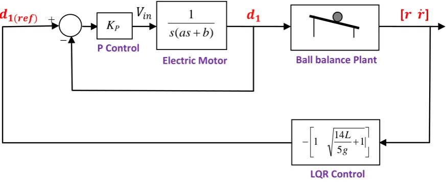
d in an external control loop. These values are used as references for the controller of the electric motors in internal control loop. This concept is illustrated for agent
1
d in Figure 3. Agent 2 has similar control strategy. In inner loop, a simple proportional controller with parameter KP is employed. Using this P-controller,
transfer function of inner loop becomes:
a K s a b s a K s V s d P P in ref + + = 2 ) ( 1 ) ( ) ( (18)
We designKP in such a way that the critically damped response of electric motor is achieved. To this end:
a b KP
4
2
= (19)
4.
Simulation Results
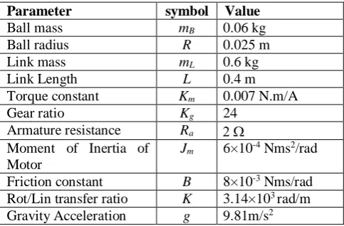
To evaluate performance of the proposed control scheme, model of mobile robot was built in MSC.ADAMS and, in order to implement controllers, it was linked to MATLAB/SIMULINK. Parameters of the simulated model are given in Table 1. By these parameters open loop transfer function of electric motor (equation (11)) becomes:
) 028 . 321 429 . 22 ( 1 ) ( ) ( 1 + = s s s V s d in (20)
and from (16) we obtain KP =1149 that results in closed loop transfer function for electric motor as:
218 . 51 313 . 14 218 . 51 ) ( ) ( 2 1 + + = s s s V s d in (21)
From (14), LQR control law for agent d1is given as:
[
1 1.0555]
( )1 t
d = X (22)
With these controllers, closed loop poles of the entire system will be located at
4 . 7 98 . 4 , 967 . 0 , 868 .
21 − − + j
− which implies on
stability of the system with a single dominant pole at
967 . 0
− which makes the behavior of the system similar to first-order stable system. This is expected to provide a satisfactory behavior is for the system.
Table 1. Parameters of simulated model
Parameter symbol Value
Ball mass mB 0.06 kg
Ball radius R 0.025 m
Link mass mL 0.6 kg
Link Length L 0.4 m
Torque constant Km 0.007 N.m/A
Gear ratio Kg 24
Armature resistance Ra 2 Ω
Moment of Inertia of Motor
Jm 6×10⁻⁴ Nms2/rad
Friction constant B 8×10⁻³ Nms/rad
Rot/Lin transfer ratio K 3.14×10³ rad/m
Gravity Acceleration g 9.81m/s2
4.1 Regulation Test
In the first simulation we assumed that the link is initially located in horizontal configuration (i.e.
0
,
0 1= 2 =
= d d
α ) and the ball is initially at rest and it is located at 0.1m distance from the middle point of the link (i.e. r=0.1, r=0) . Simulations were carried out in two different cases. In the first case, we assumed that the mobile robot does not move. In the second case, however, it was assumed that the mobile robot moves with the following motion equation:
> < < + − = 5sec t 6 125 5sec t 0 2 5 3 1 ) ( 2 3 t t t
xrobot (23)
which imposes acceleration variation of
[
5 5]
2 sm
− that
is relatively large variation. Simulation results for both cases are shown in Figure 4. When the robot does not move, as it is expected, the system can regulate the ball into middle point of the link. When the mobile robot moves and applies an external (disturbance) force to the control mechanism, the system can regulate the ball, as well. The interesting fact is that there is no significant difference between curves in simulations of two cases. This implies that the system can successfully regulate the ball even when the robot moves.
4.2 Fault Tolerance Test
One of the most interesting advantages of multi-agent systems is their fault tolerance property. That is the whole system can undergo a graceful degradation when some agents fail. To evaluate fault tolerance in the proposed mechanism, we repeated the simulation of the system for second case of previous tests. However, here we assumed that the agent d1fails at t=2 (because of for
results are shown in Figure 5. After failure of d1, agent d2 is responsible for regulating the ball. By
designed control scheme, it could re-plan its motion in order to compensate failure of d1 and complete the
control task successfully. It can be seen in Figure 5 that the mechanism could properly control the ball.
5.
Conclusions
A ball balance system was introduced as a platform to design and analyze multi-agent control system. It was illustrated that there is two approaches to control this system. In central control approach a multivariable nonlinear control should be designed for the system that is a complicated task. In distributed control approach the
task is distributed among agents, therefore simpler controllers are expected. Based upon this rationale the system was modeled. The control task was distributed among two agents and for each agent a control scheme was developed. The control scheme includes a LQR control in outer loop and a simple P-controller in inner loop. Appropriate values for control parameters were designed. To evaluate the performance of the controllers, the mechanism was constructed in MSC.ADAMS and linked to MATLAB/SIMULINK. Simulation results showed that the system can balance the ball on the link. Moreover, the system is fault tolerance as one of the agents can individually complete the control task when the other agent fails.
0 1 2 3 4 5 6 7 8
-0.05 0 0.05 0.1 0.15
r
(m)
0 1 2 3 4 5 6 7 8
-0.1 -0.05 0 0.05 0.1
time (sec).
dr
/d
t
(m
/s
)
0 1 2 3 4 5 6 7 8
-0.05 0 0.05 0.1 0.15
d1
(m)
0 1 2 3 4 5 6 7 8
-0.1 -0.05 0 0.05 0.1
time (sec.)
d 2
(m)
Case1 Case2
Case1 Case2
Case1
Cata2 Case1Case2
Fig. 4. Simulation results of balancing the ball in two cases.
Case 1: The mobile robot does not move Case 2: The mobile robot does moves with (23)
0 2 4 6 8 10
-0.05 0 0.05 0.1 0.15
r
(m)
0 2 4 6 8 10
-0.1 -0.05 0 0.05 0.1
time (sec.)
dr
/d
t
(m
/s
)
0 2 4 6 8 10
-0.05 0 0.05 0.1 0.15
d1
(m)
0 2 4 6 8 10
-0.1 -0.05 0 0.05 0.1
time (sec.)
d2
(m)
fault time
References
[1] Nilsson, N. J. “Distributed artificial intelligence”. SRI International Menlo Park CA Artificial intelligence center., 1981
[2] Shaw, M. J., and Whinston, A. B. “Learning and adaptation in distributed artificial intelligence systems.”, Distributed Artificial Intelligence, 1989; 2, 413-429.
[3] Ren, W., and Cao, Y., “Distributed coordination of multi-agent networks: emergent problems, models, and issues”, Springer, 2010
[4] Lin, P., and Jia, Y., “Consensus of a class of second-order multi-agent systems with time-delay and jointly-connected topologies”, IEEE Transactions on Automatic Control, 2010; 55(3), 778-784.
[5] Sarker, M. O. F., Dahl, T. S., Arcaute, E., and Christensen, K. “Local interactions over global broadcasts for improved task allocation in self-organized multi-robot systems”. Robotics and Autonomous Systems, 2014; 62(10), 1453-1462. [6] Akbarimajd, A., and Simzan, G., “Application of
Artificial Capital Market in Task Allocation in Multi-robot Foraging”, International Journal of Computational Intelligence Systems, 2014; 7(3), 401-417.
[7] Robu, V., Noot, H., La Poutré, H., and Van Schijndel, W. J., “A multi-agent platform for auction-based allocation of loads in transportation
logistics.”, Expert Systems with Applications, 2011; 38(4), 3483-3491.
[8] Xu, Y., Liu, W., & Gong, J., “Stable multi-agent-based load shedding algorithm for power systems. IEEE Transactions on Power Systems, 2011; 26(4), 2006-2014.
[9] Bazzan, A. L., and Klügl, F., “A review on agent-based technology for traffic and transportation”, The Knowledge Engineering Review, 2014; 29(03), 375-403.
[10] Nagata, T., and Okamoto, K. “A multi-agent based optimal operation for microgrid. In (SMC), In Proc. 2014 IEEE International Conference on Systems, Man and Cybernetics, 2014; 3791-3796
[11] Jonban, M. S., Akbarimajd, A., and Javidan, J. “Intelligent Fault Tolerant Energy Management System With Layered Architecture for a Photovoltaic Power Plant.”, Journal of Solar Energy Engineering, 137(1), 2015; 011004.
[12] Chang, Y. H., Chang, C. W., Tao, C. W., Lin, H. W., and Taur, J. S., “Fuzzy sliding-mode control for ball and beam system with fuzzy ant colony optimization”, Expert Systems with Applications, 2014; 39(3), 3624-3633.
[13] Whelan, J., and Ringwood, J. V., “A Demonstration Rig For Control Systems Based On The Ball and Beam With Vision Feedback”. In Proc. of the IFAC Symposium ACE, 2014, 94, 9-15