© 2017 IJSRST | Volume 3 | Issue 1 | Print ISSN: 2395-6011 | Online ISSN: 2395-602X Themed Section: Science and Technology
Implementation of IOT with Esp8266 Part I - Creating A Prototype
K. Priyanka Srinivasulu Reddy
Research and Development Engineer, Videocon Industries Ltd., Aurangabad, Maharashtra, India
ABSTRACT
This paper aims at presenting a practical approach to IOT driven smart home devices. This paper describes in detail - a) The Smart Home concept b) Our concepts to model the Smart Home using smart devices c) Development of a prototype for controlling smart home devices through IOT and d) Controlling of dumb devices through IOT by the means of Wifi driven chipset solution – ESP8266. Contrary to the other projects, this work is directed towards a sensors approach and an ontology modelling of the Smart Home. This work has the originality to take into account the real heterogeneity of information present in a habitat. This paper is a good overview to present what is a Smart Home and which are the necessary hardware and software components to make a Smart Home. Smart Home concept has been implemented using smart devices, a wifi driven IOT chipset solution – ESP8266 and controlling of dumb devices through IOT by the means of this Wifi driven chipset.
Keywords:
Internet of things (IOT), smart TV, smart devices – hand held devices, smart wearables, wireless sensor network, ESP8266,I.
INTRODUCTION
Definitions
: As identified by Atzori, Internet of Things can be realized in three paradigms – internet-oriented (middleware), things internet-oriented (sensors) and semantic-oriented (knowledge). Although this type of delineation is required due to the interdisciplinary nature of the subject, the usefulness of IoT can be unleashed only in an application domain where the three paradigms intersect.The RFID group defines Internet of Things as – The worldwide network of interconnected objects uniquely addressable based on standard communication protocols. In our definition, we make the definition more users centric and do not restrict it to any standard communication protocol. This will allow long-lasting applications to be developed and deployed using the available state-of-the-art protocols at any given point in time. Our definition of Internet of Things for smart environments is – Interconnection of sensing and actuating devices providing the ability to share information across platforms through a unified framework, developing a common operating picture for enabling innovative applications. This is achieved by seamless ubiquitous sensing, data analytics and
information representation with Cloud computing as the unifying framework.
IoT Elements:
We present a taxonomy that will aid in defining the components required for Internet of Things from a high level perspective. Specific taxonomies of each component can be found elsewhere. There are three IoT components which enable seamless ubi-comp: a) Hardware - made up of sensors, actuators and embedded communication hardwareb) Middleware - on demand storage and computing tools for data analytics and
c) Presentation - novel easy to understand visualization and interpretation tools which can be widely accessed on different platforms and which can be designed for different applications. In this section, we discuss a few enabling technologies in these categories which will make up the three components stated above.
Smart
Home
Environment:
With thetalking to each other, machine-to-machine communications and person-to-computer communications will be extended to “things”. Key technologies that will drive the future IoT will be related to Smart sensor technologies including WSN, Nanotechnology and Miniaturization. The automation of home settings to act according to the inhabitant requirements is termed as intelligent home automation system. [1, 4, 6]
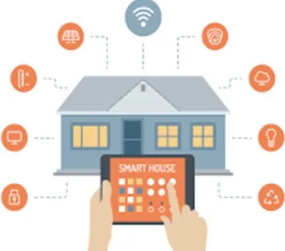
Figure 1.1: Smart Home Concept
Smart Homes, shown in figure 1.1, also known as automated homes, intelligent buildings, and integrated home systems are a recent design development. Smart homes incorporate common devices that control features of the home. Originally, smart home technology was used to control environmental systems such as lighting and heating, but recently the use of smart technology has developed so that almost any electrical component within the house can be included in the system. Moreover, smart home technology does not simply turn devices on and off; it can monitor the internal environment and the activities that are being undertaken whilst the house is occupied. The result of these modifications to the technology is that a smart home can now monitor the activities of the occupant of a home, independently operate devices in set predefined patterns or independently, as the user requires.
In general, an intelligent home automation system consists of clusters of sensors, collecting different types of data, regarding the residents and utility consumption at home. Systems with computing capabilities analyse the assimilated data to recognize the activities of
inhabitants or events. These can automate the domestic utilizations effectively and also can support the inhabitant by reducing the costs and improving the standard of living. In the recent past, several research activities were actively involved with IoT. Most of the research activities related to IoT are confined to management of resource constraint devices, and different mechanisms of interconnection. The future cyber-age networked infrastructures of household appliances in homes are likely to be reliant on sensors embedded in/on the infrastructure. Such technologies will act as a catalyst to the evolution of a new generation of services that will have a great impact on the social and technological eco-system. It can be envisaged that the next generation systems and services will encompass several domains such as e-Governance, Health Care, Transportation, Waste Management, Food Supply Chains, and Energy & Utilities.
New technologies and applications built on top of smart devices may fulfil the vision of Intelligent Infrastructure. To date, there has been no complete development of a monitoring smart home of commercial perspective, nor any investigation into how such a house is perceived by either the inhabitants or their careers. The smart homes designed so far are for different purposes such as information collection and decision support system for the wellbeing of the inhabitants, storing and retrieving of multimedia data and surveillance, where the data is captured from the environment and processed to obtain information that can help to raise alarms, in order to protect the home and the inhabitants from burglaries, theft and natural disasters. [2, 3, 5, 7]
II.
DESIGN AND DESCRIPTION OF
PROTOTYPE
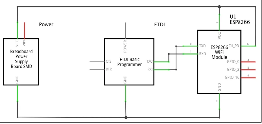
Figure 1.2: Circuit Diagram
Hardware and Software Requirements:
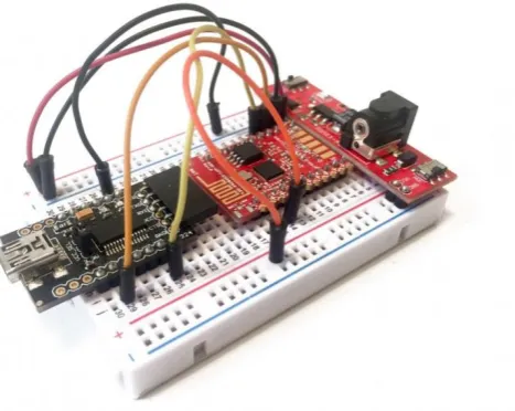
For this project, you will of course need an ESP8266 chip. I used the Olimex ESP8266 module, but any ESP8266 module will work fine here. You will also need some way to control your lamp or other devices. I originally used a simple relay for my tests, but I quickly moved to a PowerSwitch Tail Kit which allows to simply & safely plugging high voltage devices to your projects. You will also need a 3.3V FTDI USB module to program the ESP8266 chip. Finally, you will also need some jumper wires & a breadboard. [9, 11, 12]
This is a list of all the components that will be used in this guide:
ESP8266 Olimex module
Breadboard 3.3V power supply
3.3V FTDI USB module
PowerSwitch Tail Kit
Breadboard
Jumper wires
Note that you will also need a device to control. I used a simple 30W desk lamp as a test device, but you can also use any other device in your home (if the power rating is lower than the maximum power accepted by the Power Switch Tail Kit). You can also just use a simple relay for
test purposes. On the software side, we will use the Arduino IDE to configure the ESP8266 chip.
I will let you see my guide on how to set up the ESP8266 for a first use & how to upload a sketch: https://www.openhomeautomation.net/getting-started-esp8266/
You will also need to install several libraries for this project:
aREST
aREST UI
Hardware Configuration
Arduino Programming:
We are now going to write the code required to control our lamp remotely. Note that we want a completely autonomous operation of the device. The ESP8266 will have to handlerequests coming from your browser, display a simple HTML page with two buttons (On & Off), and then control the PowerSwitch Tail Kit accordingly. To do all that, we will use the powerful aREST UI library that makes it really easy to build graphical interfaces.As we are using the Arduino IDE for the ESP8266, we will simply write some Arduino code here. It starts by declaring which libraries we are going to use:
#include <ESP8266WiFi.h> #include <aREST.h> #include <aREST_UI.h>
Then, we declare the aREST UI object:
aREST_UI rest = aREST_UI();
After that, you will need to include your WiFi name & password:
constchar* ssid = "your_wifi_name";
constchar* password = "your_wifi_password";
Now, in the setup() part of the sketch, we actually build the interface of the project, with a button linked to pin number 5 of the board:
rest.title("Relay Control"); rest.button(5);
After that, we connect the board to the WiFi network:
WiFi.begin(ssid, password);
while (WiFi.status() != WL_CONNECTED) {
delay(500); Serial.print("."); }
Serial.println("");
Serial.println("WiFi connected");
// Start the server server.begin();
Serial.println("Server started");
// Print the IP address
Serial.println(WiFi.localIP());
Then, in the loop() part, we handle incoming connections with the aREST UI library:
WiFiClient client = server.available(); if (!client) {
return;
}
while(!client.available()){ delay(1);
}
rest.handle(client);
Note that you can find all the code for this project on the corresponding GitHub repository:
https://github.com/openhomeautomation/esp8266-relay
I used the Arduino IDE to upload the code to the board. First, select the ESP8266 board inside the Arduino IDE. Make sure that you choose the option that corresponds to your board, especially if you are using the Olimex board like I did for this tutorial. Also make sure that you changed your WiFi name & password inside the sketch.
Then, put the chip in bootloader mode by connecting GPIO0 to GND, and then power cycle the board by switching the power supply off & then on again. Then, upload the sketch to the board. Once it is done, disconnect GPIO0 from GND, and power cycle the board again.
Results:
1. Boot up the ESP module by connecting to 5V & GND.
2. Wifi local network „Priyanka_IOT‟ will be created by ESP module.
3. Connect to this Wifi network as shown in figure 1.4.
Figure 1.4: Results 1 - Connect to Network
4. Start internet explorer and enter IP address : 192.168.4.1/led/1
This will turn ON led as shown in figure 1.5.
Figure 1.5: Results 2 - LED is ON
5. Start internet explorer and enter IP address : 192.168.4.1/led/0
This will turn OFF led as shown in figure 1.6.
III.
CONCLUSION
This paper, presents what a Smart Home is, which components are necessary to make a Smart Home. Firstly, a concept regarding indoor environment and smart home automation using Smart TV as the central monitoring and man to in presented machine interface unit. Second, the design and description of a prototype for controlling smart and dumb home appliances through IOT by the means of a Wifi driven chipset solution – ESP8266 is described in detail. In this, the hand held smart devices such as smart phones, tablets, smart wearables etc. act as the central monitoring interface for monitoring and control of smart home appliances. Lastly, the working and results of the prototype are given.
This Application notes detailed how to install software for developing IoT applications and testing them on home appliances, using the ESP8266-01. It then showed how to create Android program to control home appliances using this ESP module. The results with images were thereby depicted. The links provided in the rest of this document can be used to learn about IoT Development, or can be used in case of unforeseen problems occurring while following this document.
In future scope, this technology of IoT can be used to monitor and control all home appliances remote through WiFi network and smart devices by connecting appropriate relays and power supply.
IV.REFERENCES
[1] The Smart Home Concept : Our Immediate Future [2] https://www.researchgate.net/publication/2246964
59_The_Smart_Home_Concept_our_immediate_f uture
[3] The Internet of Things and The Web of Things by Emmanuel Baccelli, Dave Raggett
[4] Towards the Implementation of IoT for Environmental Condition Monitoring in Homes by Sean Dieter Tebje Kelly, Nagender Kumar Suryadevara, and Subhas Chandra Mukhopadhyay, Fellow, IEEE
[5] D. Surie, O. Laguionie, and T. Pederson, “Wireless sensor networking of everyday objects in a smart home environment,” in Proc. Int. Conf. Intell. Sensors, Sensor Netw. Inf. Process., 2008, pp. 189–194.
[6] H. Sundmaeker, P. Guillemin, P. Friess, S. Woelffle, Vision and Challenges for Realizing the Internet of Things. Luxembourg, Germany: European Union, 2010, ISBN 9789279150883. [7] Internet 3.0: The Internet of Things, Analysys
Mason, Singapore, 2010.
[8] K. Ashton, That ―Internet of Things‖ Thing, RFiD Journal. (2009).
[9] H. Sundmaeker, P. Guillemin, P. Friess, S. Woelfflé, Vision and challenges for realising the Internet of Things, Cluster of European Research Projects on the Internet of Things - CERP IoT, 2010.
[10] J. Buckley, ed., The Internet of Things: From RFID to the Next-Generation Pervasive Networked Systems, Auerbach Publications, New York, 2006.
[11] M. Weiser, R. Gold, The origins of ubiquitous computing research at PARC in the late 1980s, IBM Systems Journal. (1999).