ISSN (e): 2250-3021, ISSN (p): 2278-8719
Vol. 04, Issue 01 (January. 2014), ||V6|| PP 42-55
Response the Cylindrical Elevated Wheat Storage Silos to Seismic
Loading
Hamdy H.A. Abdel-Rahim
11(Department of civil Engineering., Faculty of Engineering, Assuit University ,Egypt
Abstract : - The elevated cylindrical storage silos are lifeline structures and strategically very important, since
they have vital use in industries. Silos are special structures subjected to many different unconventional loading conditions, which result in unusual failure modes. In addition silos are cantilever structures with the material stacked up very high vertically. The earthquake response of silo structures for the storage of bulk solids differs for elevated silos and silos supported directly on the ground. The walls of different type of silos are subject to earthquake loads from the stored mass, and these may substantially exceed the pressures from filling and discharge. The assessment of horizontal action of ensiled material due to seismic vent seems to be particular interest. This paper is concerned with the earthquake response of these structures, which has received little attention to date. A cylindrical silo wall and bulk solid is modeled by three dimensional finite solid l elements. The interaction effect between the silo wall and bulk solid is taking account by using the nonlinear approach proposed by Duncan and Chang. A then interface layer proposed by Desia is applied to describe the phenomena taking place on the surface between the granular material and silo wall. Coulomb's friction low was used for modeling of wall friction. An incremental iterative finite element technique is applied for dynamic analysis of wheat silos using SAP2000 structural software package. In this research seven reinforced concrete silo models with different height to diameter ratios were studied and analyzed in time history by using earthquake acceleration 0.5g applied to silos models. The resulting finite element silo pressures as the silo is full with and without earthquake excitation are compared with theoretical filling and discharging pressure. The result obtained revealed that the elevated silos response is highly influenced by the earthquake characteristics and is depending on the height to diameter ratio. Also the findings indicate that the squat silo (large diameter and height) are more resistance to the earthquake and more economical. The seismic responses of the elevated wheat silo such as top displacement, normal forces, shearing forces and bending moments in silo support have been assessed for earthquake records.
Keywords: - seismicbehaviour, bulk and granular solids ,time history analysis, filling, discharging, wheat silos
I.
INTRODUCTION
Containers used for storing bulk solids are usually called bins, bunkers, silos, or tanks. Although there is no generally accepted definition for these terms, shallow structures containing coal, coke, ore, crushed stone, gravel, and similar materials are often called bins or bunkers, and tall structures containing materials such as grain and cement are usually called silos (Li 1994). A number of representative silos that were damaged or collapsed during recent earthquakes around the world will be presented in this section. Possible causes of failures and potential measures to prevent damage will be discussed. Earthquakes frequently cause damage and/or collapse in silos resulting in not only significant financial loss but also loss of life. For example, during the 2001 El Salvador earthquake three people lost their lives as a result of a silo failure (Mendez 2001).
There are few researches that have tried to investigate the behavior of silos under earthquake loading with considering granular materials-structure interaction. Holler and Meskouris have tried to investigate the behavior of silos under earthquake loading. They have tested different hypoplastic models and concluded that the Von Wolffersdorf's hypoplastic model with intergranular strain extension is the most effective material aw for describing. The time dependent cyclic behavior of granular material. Nateghi and Yakhchalian can be concluded in silos with lower height to diameter ratios, the vibration of granular material inside silo in parts situated near the top surface of granular material plays an important role in the dominant frequency of response. The stiffness of granular material situated in layers near the top surface of granular controls the dominant frequency of response. Also the concluded the the dynamic pressure at the upper half of silos height have considerably exceeded the Eurecode pressure, Silvestri, Gasparini, and Tromdetti indicate that in the case of silos characterized by specific (but usual) height/diameter slenderness ratio, the portion of grain mass that interacts with the silo walls turns out to be noticeably lower than the total mass of the grain in the silo. The effect of lateral loads can be significant especially on larger silos containing heavier material since the magnitude of the horizontal seismic load is directly proportional to the weight of the silo (Dogangun et al. 2009).
II.
MODELING OF GRANULAR MATERIALS
The proposed numerical model of the cylindrical R.C. silo bin system consists of three types of finite elements, see Fig.1
reinforced concrete silo bin wall elements,
Fig. 1 Conception of numerical discretisation of axi-symmetric silo wall-bulk solid system.
Hypothetical contact layer (interface layer),
Bulk solids elements.
The following assumptions were formulated for the first numerical FEM model taking into account the imposed actions coupled with permanent bulk solid pressure (Gnatowski, 1998):
– The FEM analysis was applied to the cylindrical R.C. wall structure (considered here as a thin cylindrical shell),
– Constant distribution of imposed action on the silo wall over the wall perimeter, – Granular, non-cohesive particulate solid,
– The computational model based on real behaviour of bulk solid with application of the nonlinear elastic theory,
– The reinforced concrete silo wall described by constitutive laws of elastic linear theory of the cylindrical shell.
To describe the phenomena taking place on the surface between the granular medium and the silo wall, an adaptation of a thin contact layer (interface element) proposed by Desai et al., 1986 [4] is applied. The following matrix has been used in the formulation of the problem:
i i
G
SYM
d
d
d
d
d
d
D
0
0
0
]
[
1 2 1
2 2 1
(1)
0
.
1
)],
2
1
)(
1
/[(
]
[
)],
2
1
)(
1
/[(
)]
1
(
[
2 2 2 2 1
m m m m m m m mE
d
E
d
Where: Em, and m are the modulus of elasticity and Poisson’s ratio of bulk solid, respectively.
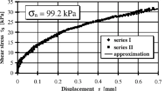
To define shear modulus Gi given in matrix (1) an empirical relationship between shear stresses s and relative displacement s at the contact zone should be obtained experimentally from direct shear apparatus tests. On the above basis, the following formula has been used:
where: n experimental parameters, L displacement modulus [mm], the coefficient of friction of bulk solid at the contact surface, n stress in normal direction to the contact surface, s,max maximum value of shear stress. The experimental relationship obtained here in the formulation
(For wheat) in the direct shear apparatus is presented in Fig. 2.
Taking into account = s/gi and Gi = ds/dthe following formula was obtained
n i n i n i s i
L
g
g
L
L
g
n
d
d
G
exp
) 1 (The experimental relationship obtained here in the formulation (for wheat) in the direct shear apparatus is presented in Fig. 2 (Lapko et al. 2003).
Fig. 2 Experimental curves obtained from direct shear apparatus tests for wheat considered in the FEM model description.
For the needs of numerical analysis of the interaction effects between silo wall structure and bulk solid, the nonlinear approach proposed by Duncan and Chang, 1970 as been here adopted. The stiffness matrix of the finite element modelling the mass of bulk solid is used in the following way:
m mG
SYM
d
d
d
d
d
d
D
0
0
0
33 23 22 13 12 11Where the components of the matrix are denoted as follows:
In order to determine the modulus of elasticity Em of bulk solid, the numerical iterations procedures proposed by Duncan and Changwere applied:
m
a a f
m
P
KP
c
Q
E
32
3 3 1
sin
2
cos
2
)
)(
sin
1
(
1
Where: 1 and 3 principal stresses (max. and min.), c cohesion of bulk solids, internal friction angle, K and m material parameters, Pa value of atmospheric pressure, Qf experimental coefficient. This assumptions and relationships were elaborated with the use of the iteration algorithm and then applied in a computer program
Gnatowski, 1998.
In the general issues concerning the actions provoked by earthquake ground motion on the walls of flat-bottom grain silos, the assessment of the horizontal actions seems to be of particular interest. These actions are usually evaluated under the following hypotheses:
(i). Stiff behaviour of the silo and its contents (which means considering the silo and its contents to be subjected to ground accelerations);
(ii). The grain mass corresponding to the whole content of the silo except the base cone with an inclination equal to the internal friction angle of the grain is balanced by the horizontal actions provided by the walls (supposing that the seismic force coming from the base cone is balanced by friction and therefore does not push against the walls).
This design approach is not supported by specific scientific studies; as a matter of fact, even though there are many papers on the behaviour of liquid silos under earthquake ground motion (Hamdan 2000, Nachtigall 2003), there are no examples of scientific investigation into the dynamic behaviour, let alone under earthquake ground motion, of flat-bottom grain silos.
The main goal of the paper is to present analytical developments devoted to the evaluation of the effective behaviour of flat-bottom silos containing grain, as subjected to constant horizontal acceleration and constant vertical acceleration. In more detail, the developments presented here, keeping the validity of the hypothesis (i), aim to assess the effective horizontal actions that rise on the silo walls due to the accelerations, by means of analytical studies and on the basis of dynamic equilibrium considerations.
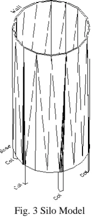
Fig. 3 Silo Model
The analyses reported here are developed by simulating the earthquake ground motion with constant vertical and horizontal accelerations (time-history dynamic analyses are not carried out). The results obtained show how these horizontal actions are far lower with respect to those that can be obtained using the hypothesis (ii).
III.
MODELING OF SILOS
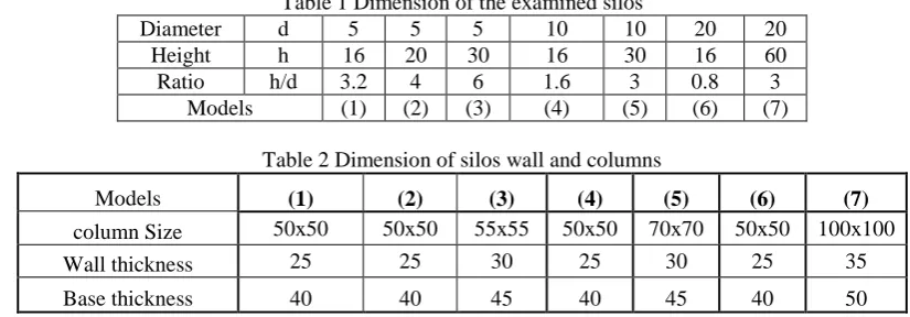
Seven finite element models of the present work were used to analyze different cylindrical silos with flat bottom. The following table 1 was the dimensions of the silos:
Table 1 Dimension of the examined silos
Diameter d 5 5 5 10 10 20 20
Height h 16 20 30 16 30 16 60
Ratio h/d 3.2 4 6 1.6 3 0.8 3
Models (1) (2) (3) (4) (5) (6) (7)
Table 2 Dimension of silos wall and columns
Models (1) (2) (3) (4) (5) (6) (7)
column Size 50x50 50x50 55x55 50x50 70x70 50x50 100x100
Wall thickness 25 25 30 25 30 25 35
Base thickness 40 40 45 40 45 40 50
III.1. Finite element model
For the finite element modeling, we used five of the element types available in the SAP2000, and to simulate the stored material we used interface elements Solid (Fig. 1). Since FEM is a continuum method, one must use a constitutive law capable of approximating the behaviour of a granular material consisting of discrete particles.
III.2. Static Conditions
It is known that the grain provides a vertical push onto the silo walls. It can be hypothesized that the vertical pressures actually tend to diminish from the core of the grain portion until they disappear when the grain meets the silo walls. A limiting schematization (that will be useful for the assessment, to guarantee safety, of the actions induced on the silo walls by the vertical accelerations, as illustrated in the following sections) is one where the grain is divided into two “equivalent” portions composed of (i) grain completely leaning against the layers below (central portion) and (ii) grain completely sustained by the walls (and therefore characterized by a null vertical pressure between one grain and another).
It has been argued that a better understanding of the properties of the ensiled materials and their interaction with the silo structure is one of the critical factors in improving design. (Johnston, 1981) .
The behavior of the granular element was described with a micro-polar hypoplastic constitutive model [(Tejchman and Gudehus, 2001), (Tejchman and Górski, 2008), (Tejchman et al., 2008) which takes into account the evolution of effective stresses and couple stresses depending on the current void ratio, stress and couple stress state, rate of deformation and rate of curvature and a mean grain diameter. The feature of this model is a simple formulation and procedure for determining the material parameters with standard laboratory experiments (Herle and Gudehus, 1999). The material parameters are related to the granulometric properties of granular materials, such as grain size distribution curve, shape, angularity and hardness of grains. The model is capable to describe a transition between dilatancy and contractancy during shearing with constant pressure and a transition between an increase and a decrease of pressure during shearing with constant volume. The finite element results are mesh-insensitive during boundary value problems involving shear localization due to the presence of a characteristic length in the form of a mean grain diameter (McKee et al., 1995) .
III.3. Static and Dynamic Wall Pressure:
The Janssen’s formula (Janssen 1895) [26] is used to predict the wall pressure of silos can be written as:
h
r
Parameter
Area
O
A
r
k
k
r
P
e
hoh
0
,
,
1
;
.
.
; (filling=0.75,Emptying=0.6),
=tan (coefficient of friction between wall and the bulk material)(f=tanFig. 4 Filling and discharging pressure according to codes(Jonssen)
Table 3 shows the parameters used in this paper for both static and dynamic analysis of the different kinds of silos.
Table 3 Mechanical properties of Spanish Horzal wheat (Vidala et al., 2008)
Property Value
Specific Weight () (KN/m3) 8.4 Young’s modulus (E) (KPa) 5129
Poisson’s ratio () 0.32
Grain-wall friction coefficient 0.2 Internal friction angle () (◦) 25 Apparent cohesion (c) (KPa) 3
Dilatancy angle (◦) 17.6
A 3D finite-element model shown in Fig. 1 was developed to study pressures on the large diameter silo wall used FEM software SAP2000. The element used to represent the stored material was 3D solid element, a cubic element defined by eight nodes with three degrees of freedom and a nodal displacement at x, y, and z. This structural element is compatible with surface-to-surface contact elements that admit different plasticity models and laws of behavior of the bulk material. This study simulates silos filled with wheat, a granular material that can be reasonably considered isotropic, particularly when it is randomly packed. Because wheat is a granular material, a law of behavior of the stored material must be used that reproduces the behavior of wheat grains with low cohesion. In this study, the bulk solid was simulated by Mohr-Coulomb model which was based on a non-associated flow rule, a perfectly-plastic Coulomb yield behavior and tension cut-off. The
Mohr-Coulomb yield equation can be written as
f
I
1
J
2
k
,where α and k are stressed dependent:,
2
3
3
cos
3
1
cos
)
sin
3
(
3
sin
)
sin
1
(
3
sin
6
,
cos
)
sin
3
(
3
sin
)
sin
1
(
3
sin
2
2 / 3 2 3 1
J
J
c
k
I1 is the first stress invariant at time t, J2 is the second deviatoric stress invariant at time t, J3 is the third deviatoric stress invariant at time t. is the friction angle (a material constant), c is the cohesion (a material constant). Although, more complex models exist, the Mohr-Coulomb model is sufficiently accurate and easy to use with numerical models.
A surface-to-surface contact model was used between the bulk solid and silo wall. Two surfaces that contactor surface and target surface made up a contact pair. The contactor surface was the out surface of bulk solid and the target surface was silo wall. Because the Young’s modulus of reinforcement concrete is about 20
0 10 20 30 40 50 60
0 5 10 15 20 25
GPa, which is much larger than the Young’s modulus of stored material, the silo wall was considered to be rigid for good convergence in this paper.
IV.
INPUT LOADING:
The dynamic analysis of the different kinds of silos will establish by time history analysis using El-Centro earthquake model as shown in Fig. 5, as 0.5g of the ground acceleration.
Fig. 5 El-Centro model vibration
V.
RESULTS AND DISCUSSIONS
Figure 6 shows the comparison between filling, discharging pressures and finite element analysis when the silo is full of wheat. As illustrated from Fig.5, the discharging pressures envelope the finite element pressures as the silo is full in the upper half of silo height except in the lower of the silo the finite element pressures envelope recommended pressures during discharging. Fig. 6 Illustrated that the result of finite element (h/d = 1 – 2) the pressure in squat silos curve come closest to the straight line. For wheat silos with great aspect ratio the peak filling pressure as the silo is full equals two times that is determined analytically from Janssen equation. However, in case of large silos with small aspect ratio the peak filling pressure due to finite element is about 1.6 times the discharging pressure determined according to Janssen equation.
i Silo type (model 1) ii Silo type (model 4) Time (sec)
acc.(cm/sec/sec)
0 600
-600
0 8 16 24 32 40
-4
1 6 11 16
0 5 10 15
Height(m)
Pressure(t/m2)
P 2
iii Silo type (model 6) iv Silo type (model 2)
v Silo type (model 5) vi Silo type (model 7)
vii Silo type (model 3)
Fig.6 Comparison between recommended filling and discharging pressures in different silos types with finite element pressures as the silo is full
Fig.7 illustrates the comparison between pressures in static and dynamic cases. All types of silos show a rise in dynamic pressure values at all heights
0
5
10
15
20
0 5 10
H
ei
gh
t(m
)
Pressure(t/m2)
P 2
e f2P PFEA
0 5 10 15 20 25 30
0 5 10 15
Height
(m
)
Pressure(t/m2)
P 2
e f2P PFEA
0 10 20 30 40 50 60
0 5 10 15 20 25
Height
(m
)
Pressure(t/m2)
P 2
e f2P PFEA
0 5 10 15 20 25 30
0 2 4 6 8
H
ei
g
h
t(
m
)
Pressure(t/m2)
i Silo type (model 1) ii Silo type (model 4)
iii Silo type (model 6) iv Silo type (model 2)
v Silo type (model 5) vi Silo type (model 7)
0
5
10
15
0 10 20 30 40
Height(m)
Pressure(t/m2)
PFEA Pwithout wheat Pwith wheat
-4
1 6 11 16
0 5 10 15 20
Height(m)
Pressur (t/m2)
PFEA Pwithout wheat Pwith wheat
0 5 10 15 20 25 30
0 10 20 30
H
ei
g
h
t(
m)
Pressure(t/m2)
PFEA Pwithout wheat Pwith wheat
0
10
20
30
40
50
60
0
10
20
30
40
50
60
H
ei
ght(
m
)
Pressure(t/m2)
vii Silo type (model 3)
Fig.7 Comparison between the obtained finite element static and dynamic pressures in different silos types
Fig.7 (h/d=16/5-16/10-16/20) illustrate the finite element filling and dynamic pressures as the silo diameters varies from 5-10-20 m. while the silo height is constant (16.0 m). In these models (Large diameter silos), The dynamic pressure values envelope the finite element filling pressure in the all points especially in the lower half of the silo height. However by increasing h/d ratio the filling pressure values envelope the dynamic pressure values in the upper half of silo height. This means that in large diameter silos ( h/d=1-2(. The vibration of granular material inside the silo part situated near the top surface plays an important role in these silos responses.
Fig.7 (i,iv,vii), (ii,v),(iii,vi) exhibits the compression of the dynamic and static pressure as the silo is full with constant diameter the height from ( 16m – 20m – 30m – 60m ) and for different h/d ratios = (3-4-5),(1.6-3) and (0.8-3) respectively. As shown in these figures, the dynamic pressure is equal to (3-5) ; (1.5 -3) and (1.6-2) times the filling pressures respectively . In the squat (Large diameter silos), the max dynamic pressure occurs at 0.65h from the silo top and equals 2 times the filling pressure.
Fig.8 shows the comparison between deformations in X direction in different silos types. As shown in Fig.8 the values of displacement in X direction in static (both cases empty and full cases) cases are negligible values with respect to the values of displacements in dynamic cases (both empty and full cases). Fig.8 illustrates the deformation of top point of the different silos types in X direction. The arrangements from high to low dynamic
deformations for both cases full and empty are
model 7,model 1,model 2, model 5,model 6 and model 3 . The ratios between deformations in full and empty cases are 3.56, 6.19, 5.91, 9.55, 12.28, and 13.94. The high values of deformation for full silos under dynamic load (earthquake) related to the sloshing effect of the bulk solid in the different cases of silos so, its X direction deformation is multiplication specially model 7, and model 3 cases.
Fig.8 Comparison between deformations in X direction in different silos types
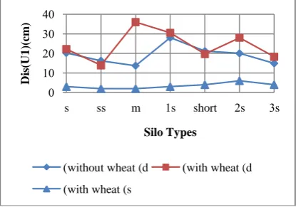
Figure 9 shows the vibration of top point of silos with different heights and diameters.
0 10 20 30 40
s ss m 1s short 2s 3s
D
is
(U
1
)(
cm
)
Silo Types
without wheat (d
( (with wheat (d with wheat (s
(
0 5 10 15 20 25 30
0 10 20 30
H
ei
g
h
t(
m
)
Pressure(t/m2)
i Silo type (model 1) ii Silo type (model 4)
iii Silo type (model 6) iv Silo type (model 2)
vii Silo type (model 3)
Fig.9 Time History of displacement in X-direction of Silos different diameter height ratios (Displacement in m)
Fig.10 shows the straining action on columns support silos models under effect dynamic in cases of empty and full cases under earthquake
i Normal Force (t) ii Shear force (t)
iii Bending Moment (m.t.)
Fig.10 Straining action on columns support silo models
From Fig.10 it is observed that the normal forces on elevated wheat silo supports in significantly increased especially in the large diameter silos with large height due to the large material stacked up very high vertically. The included normal force in the support column due to vibration of the ensiled material in such silos
0 1000 2000 3000 4000
s ss m 1s short 2s 3s
N
orm
al
F
orce
(
t)
Silo Type
without wheat (d
( (with wheat (d with wheat (s
(
0 20 40 60 80
s ss m 1s short 2s 3s
S
h
e
a
r
F
o
rc
e
(
t)
Silo Type
without wheat (d
( (with wheat (d with wheat (s
(
0 50 100 150 200
s ss m 1s short 2s 3s
B
en
d
in
g
m
o
m
en
t
(m
.t)
Silo Type
without wheat (d
( (with wheat (d
is equal to 2.4 times that induced as the silo is full only. In small diameter silos the normal force ratio in case of with and without the ground motion is equal 1-2 i.e., the effectiveness of seismic ensiled material on the support normal forces increases with the increase of material mass.
VI.
CONCLUSIONS
This paper offers a review and more understanding of available technique information with regards of behavior of wheat silos under seismic load. In this paper a seven RC wheat silos with different heights to diameter ratios has been utilizes and subject to earthquake records considering the ensiling materials. The dynamic analysis in conclude that the seismic response of silos are significantly affected by earthquake characteristics. The following conclusion can be drawn from the forgoing presentation and discussion:
The effect of the ground motion on the silos taking into the account the ensiling material has highly influence by the earthquake characteristic. In particular, it is found that the ensiling material may increase maximum pressure by 3 – 5 times the FE filling pressure in tall silos (h/d = 3 - 6). The maximum pressure occurs at the silo base.
In squat silos (h/d = 1 – 2 ) and in large diameter silo, vibration of ensiled material increases the silo wall pressure by two times the FE filling pressure without earthquake. The maximum occur at 0.65h from the silo top.
The silo top displacement provides pronounced significant responses due to strongly variation of displacement impulsations in the squat silos of small and large diameter with ratio (h/d = 1 – 2) while, in tall silos having the same diameter the seismic load cause the extreme top displacement with small and quiet fluctuations due to the large mass of ensiled materials ion tall silos.
The pressure increase due to the ensiled wheat during the ground motion is considerable larger than that recommended discharging pressure resulting from multiply Janssen equations by some factors. Consequently these dynamic pressures appear due to the ensiled materials govern the practical design of those silos.
The actions provoked by the earthquake ground motion on the ensiled material lead to remarkable increase in the normal, shear forces and bending moments on the supports the effect of ensiled material turns out to be noticeably in large diameter silos.
The effect of ensiled material in silos during the ground motions deserve more attention and should be included in the future versions of seismic codes.
REFERENCES
[1] Bandyopadhyay K, Cornell A, Costantino C, Kennedy R, Miller C, Veletsos A. (1995),"Seismic design and evaluation guidelines for the Department of Energy high-level waste storage tanks and appurtenances", Department of Advanced Technology, Brookhaven National Laboratory, Associated Universities.
[2] Bechtoula, H., and Ousalem, H. (2005), “The 21 May 2003 Zemmouri (Algeria) earthquake damages and disaster responses”, J. Adv. Concr. Technol., 3(1), 161–174.
[3] CSI, 2005. SAP2000, "Static and Dynamic Finite Element Analysis of Structures", Advanced9.1.4, Computers and Structures, Inc., Berkeley, California.
[4] Desai C.S., Zaman M.M., J.G. Lightner, H.J. Siriwardane (1984), "Thin-layer element for interfaces and joints", International Journal for Numerical and Analytical Methods in Geomechanics, 8 19–43.
[5] Dogangun, A., Karaca, Z., Durmus, A., Sezen, H. (2009), "Cause of Damage and Failures in Silo Structures", Journal of Performance of Constructed Facilities ASCE, Vol. March-April. P. 65-71
[6] Duncan J.M., Chang C.Y. (1970), ”Nonlinear analysis of stress and strain in soils, Journal of the Soil Mechanics and Foundations Division", Proceedings of the ASCE, 96 (SM5).
[7] ECCS. European recommendations for steel construction(1988), "buckling of shells", 4th ed. Brussels: European Convention for Constructional Steelwork.
[8] EQE. (1999)., “Chichi, Taiwan earthquake of September 21, 1999 (M7.6).” An EQE Briefing, (http://www.absconsulting.com/resources/ Catastrophe (Reports/Chichi-Taiwan-1999.pdf) (Jan. 29, 2008).
[9] European committee of standardization(2006), Eurocode 8:"Design of structures for earthquake resistance", part 4, Silos, tanks and Pipe lines .
[10] Gnatowski M. (1998), "Statical analysis of r.c. concentric silo bins taking into account the interaction between wall structure and bulk solids", PhD thesis, Bialystok, , in Polish.
[12] Herle I., Gudehus G. (1999), "Determination of parameters of a hypoplastic constitutive model from properties of grain assemblies", Mechanics of Cohesive-Frictional Materials, 4 (5) 461–486.
[13] Holler, S. and Meskouris, K. (2006), "Granular material silosand dynamic Excitation: numerical simulation and experimental validation", Journal of structural Engineering, Vol. 132, No.10, 1573-1579 [14] Johnston, F. T., (1981),"Silo problems". In Proc. 6th Powder and Bulk solids Con$, Rosemont, Illinois,
pp 97-102
[15] Janssen, H.A. (1895), " Versuche uber Getreidedruck in Silozellen", Z. Vereines Deutscher Ingenieure 39:1045-1049.
[16] Li, H. (1994), “Analysis of steel silo structures on discrete supports.” Ph.D. thesis, Univ. of Edinburgh, Edinburgh, Scotland, U.K.
[17] McKee S.L., T. Dyakowski, R.A. Williams, T.A. Bell, T. Allen(1995), "Solids flow imaging and attrition studies in a pneumatic conveyor, Powder Technology", 82 105–113.
[18] Mendez, D. _2001_. “Stunned Salvador suffers second deadly quake in a month” The BG News, Feb. 14, [19] http://media.www.bgnews.com/media/storage/paper883/news/2001/02/14/World/Stunned.Salvador.
Suffers.Second.Deadly.Quake.In.A.Month-1283510.shtml, Jan. 22, 2008_.
[20] Moran, D., Ferver, G., Thiel, C., Stratta, J., Valera, J., and Whylie, L. (1975). “Lima, Peru Earthquake of October 1974.” A Reconnaissance Rep.,
[21] Nachtigall, I., Gebbeken, N., Urrutia-Galicia, J.L. (2003), "On the analysis of vertical circular cylindrical tanks under earthquake excitation at its base. Engineering Structures", Vol. 25, p. 201–213.
[22] Nateghi, F. and Yakhchalian, M. (2012),"Seismic Behavior of Silos With Different Height to Diameter Ratios Cosidering Granular Material structural interaction", IJE transaction B: Applications, Vol. 25, No.1,
[23] National Geophysical Data Center _NGDC_. _1998_. “Earthquake damage, the Armenian SSR, December 7, 1988”, NGDC Natural Hazards Slide Set Thumbnails Header, http://www.ngdc.noaa.gov/nndc/struts/ results? eq_1_11&t_101634&s_0&d_2d&_22_ _Jan. 26, 2008_. [24] Niemunis, A. and Herle, I. (1977), "Hypoplastic model for cohesionless soils with elastic strain range",
Mechanics of Cohesive Materials, Vol. 2, No.4, 279-299.
[25] Rotter JM.(1990), " Local inelastic collapse of pressurised thin cylindrical steel shells under axial compression", Journal of Structural Engineering, ASCE;116(7):1955–70.
[26] Sezen, H., Livaoglu, R., and Dogangun, A. (2008). “Dynamic analysis and seismic performance evaluation of above-ground liquid containing tanks”, Eng. Struct., 30_3_, 794–803.
[27] Silvestri, S., Tromdetti, T. and Gasparini, G. (2008),:"Flat-Bottom Grain Silos Under Earthquake Ground Motion", The 14th world conference on earthquake engineering, October 12-17, Beijing, China.
[28] Silvestri, S., Tromdetti, T. and Gasparini, G. (2012),:"On the Eevaluation of the horizontal Forces Produced by Grain-Like Material Inside Silos During earthquakes",Bull Earthquake Eng. 10: 1535-1560. [29] Tejchman J., Gudehus G. (2001), "Shearing of a narrow granular strip with polar quantities",
International Journal for Numerical and Analytical Methods in Geomechanics 25 1–28.
[30] Tejchman J., Górski J. (2008), "Computations of size effects in granular bodies within micro-polar hypoplasticity during plane strain compression", International Journal of Solids and Structures 45 (6) (2008) 1546–1569.
[31] Tejchman J., W. Wu, R. Borja (Eds.) (2008), "FE modeling of shear localization in granular bodies with micro-polar hypoplasticity", Springer,
[32] http://www.eeri.org/lfe/pdf/peru_lima_eeri_preliminary_reconnaissance.pdf, Jan. 26, 2008.
[33] USGS. _2003_. “Historic earthquakes, magnitude 6.8 Northern Algeria.” _http://neic.usgs.gov/neis/eq_depot/2003/eq_030521/, Jan. 27, 2008.
[34] Vidala P., Gallegob E., M. Guaitac, F. Ayugad. (2008), “Finite element analysis under different boundary conditions of the filling of cylindrical steel silos having an eccentric hopper “, Journal of Constructional Steel Research 64 480–492.
[35] VonWolffers dorff, P.A. (1996),"A hypoplastic relation for granular materials with a predefined limit state surface", Mechanics of Cohesive Materials, Vol. 1, No.3, 215-271.