EFFECT OF PARAMETER VARIATION ON CHARACTERISTICS OF
LINEAR ANALOG VLSI CIRCUITS USING SIMPLE
MATHEMATICAL EQUATION
Baldev Raj*1 and G. M. Bhat2
1
Department of Electronics and Communication Govt. College of Engineering and
Technology Jammu.
2
Institute of Engineering and Technology Safapora USIC, University of Kashmir.
Article Received on 19/09/2017 Article Revised on 10/10/2017 Article Accepted on 31/10/2017
ABSTRACT
In this article we analyze the effect of various parameter variations on
linear analog circuits. It is very necessary that the characteristics of
circuit should be in stable form when there is some changes in value of
any circuit parameter. Our studies focus on to get the knowledge how
the system output depends upon the parameter of circuit. We also
model various circuits in this article to prove the effect of the parameter on output of
system.In this article we perform analysis on three circuits. These are RLC circuit, Sallen
Key circuit and Biquadratic filter circuit. All analysis and calculation done in this article are
performed by using MATLAB software.
KEYWORDS: Parameter, Sensitivity, Varation, Circuits, Biquadratic.
INTRODUCTION
The output of any system depends upon the component associated with it. So it is very
necessary to know the dependence of each componet bhaviou on characteristics of circuit.
Some elements affect more and some affect less,but there is affect on system output if there is
World Journal of Engineering Research and Technology
WJERT
www.wjert.org
SJIF Impact Factor: 4.326*Corresponding Author Baldev Raj
Sensitivity analysis of analog circuit provide us the information about various component
present in the circuit. With the help of sensitivity analysis we also know about the component
characteristics variation in circuit and its effect on performance of system output.[9,10]
Basic Principle of Analysis
A simple definition of sensitivity is how much specific system behavior/characteristic
changes as a individual component value changes.[11,12] The general equation for sensitivity
analysis is given below
(1)
Equation (1) is the general mathematical definition of circuit sensitivity: Where S represent
sensitivity, X represent changing element/component and Y is the characteristic of circuit
which one want to evaluate as component value is varied. The middle part of this equation
shows that the percentage that the dependent variable Δy/y changes, relative to the percentage that the independent variable Δx/x changes. The sensitivity analysis done by using these
formulae derived below. Let’s take a transfer function H(s).
H(s) = (2)
Here N(s) represent the numerator part of transfer function and D(s) represent the
denominator part of transfer function. From equation (1) and equation (2),we write a new
equation which is same as equation (1). But its variable name are changed to make our
calculation easy. In general, the AC-sensitivity is given by the following equation:
Substituting equation (1) into (2) and applying the chain rule have
Here W is the component which one want to vary w.r.t. circuit transfer function. By using
above equation (3) we can calculate the sensitivity of circuit any circuit.
Effect of Parameter Variation on Linear Analog VLSI
As we know that all circuit characteristics are function of their element values of circuit.
Filter characteristics also dependent on elements values of circuit. Most filter very sensitive
to their component values. Sensitivity analysis perform a major role to choose the component
values according to their sensitivity.[13]
There are many was to calculate the sensitivity of filters with respect to their component
value. One way is that analysis AC transfer behavior of filter with component variation. For
simplicity here we write transfer function with Q (quality factor) and (natural
frequency).[14]
The transfer function of RLC filter circuit is given below
= = (4)
Similarly
= = (5)
(7)
Q= (8)
Using nominal values of RLC circuit the Q=0.707.by using general equation of sensitivity the
sensitivities of and Q are given below.
Sensitivity using Q (quality factor)
Figure 1: Circuit diagram of RLC filter circuit.
As we saw that resistor value does not depends upon natural frequency in above equation.
Figure 2: Variation of w.r.t Q.
Figure 3 shows the variation of w.r.t quality factor. Because it is most sensitive component
in this circuit (in term of quality factor sensitivity).By using equation (3) and equation (6) we
derive sensitivities of components which are given below.
Here W is the component which we want to vary. So W=
=L1
= (9)
Similarly we calculate for .
= (10)
= (11)
Here we plot sensitivity of passive elements with nominal values as well as some tolerance
provided to nominal value and by using this we get the information related to sensitivity of
elements in RLC circuit.
With the help of sensitivity analysis one also know about the tolerance specified at the time
of design in particular element. Designer can provide cheap elements which does not affect
circuit characteristics. By using equation (10), (11) and (12).
We analyzed the sensitivity of RLC filter circuit.
Figure 4: Sensitivity of capacitor in RLC circuit.
In Figure 4, 5 and 6 we plot sensitivity analysis using nominal values of component and also
provide some tolerance form their nominal value.
Effect of Parameter Variation in Sallen-Key Filter
Sallen-key filterone of the most common filter.[14,16,17] The transfer function of this filter is
(12)
Where K= 1+
(13)
(14)
Sensitivity of K w.r.t Q is
(15)
(16)
Sensitivity of active filter component w.r.t is
(17)
=0 (18)
From above equation it is clear that natural frequency sensitivities of passive filter is ±0.5%
or Zero. But Q sensitivities are little complex.
The nominal values of component in Sallen key filter are R=10KΩ and C=16nF.[10]
Figure 6: Sallen-key filter circuit diagram.
The Sallen key filter in figure is 1 kHz (low pass filter) with Q=1. In this filter we vary the
value of by keeping natural frequency constant. We vary the value of from 1KΩ to
19.9KΩ. At the Q goes to very high so we avoided it. As we know that is main
gain determine component in filter changing with Q in Figure10.Figure 11 shows the
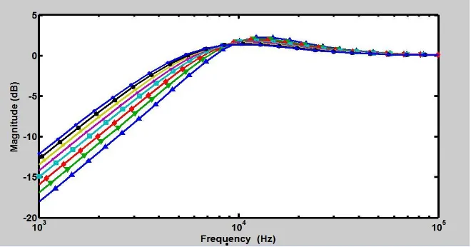
Figure 7: Response of Sallen-key filter by varying from 1KΩ to 19.9KΩ.
5. Effect of Parameter Variation in Biquadratic Filter Circuit
Figure 12 shows the biqquadratic filter circuit. Now we perform analysis on this circuit and
analyze the effect of parameter variation on characteristics of circuit. First we calculate the
transfer function of filter circuit and then apply sensitivity analysis as given in equation
(1),[18,19,20]
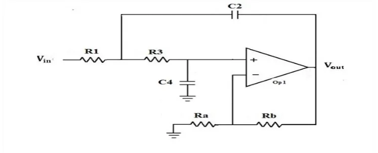
Figure 8: Circuit diagram of Biquadratic filter circuit.
Now we calculate the transfer function of biquad filter circuit from above Figure 12
(19)
(20)
(21)
(22)
By putting the value of equation (20) in equation (21) we get
(23)
By putting the value of equation (20) and (21) in equation (22) we get
(24)
Here U= (25)
(26)
Equation (26) represent the transfer function of biquadratic filter circuit.
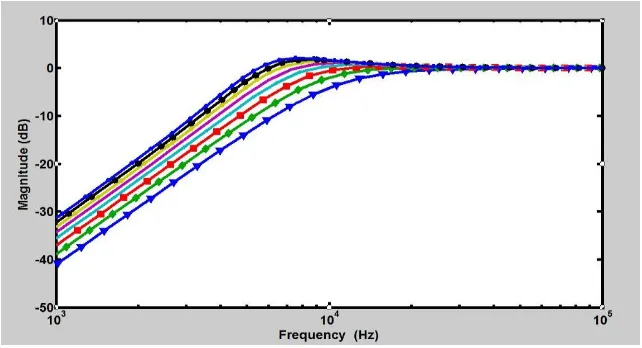
Figure 9: Sensitivity of in Biaquadratic filter circuit.
As shown in Figure 13 if we increase the value of the plot shift upward and constant at 3
U=
(27)
Using above equation we can find the sensitivity of in biquadratic filter circuit.
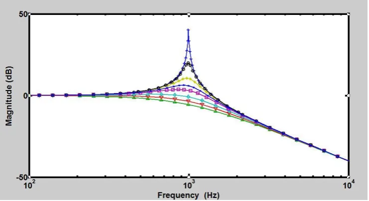
Figure 10: Sensitivity of in Biquadratic filter circuit.
Using equation 26 we did sensitivity analysis for and we found two results.
Using sensitivity analysis of we know that if we decrease the value then we can
calculate tolerance very easily. In sensitivity analysis we keep all values nominal except
and also keep frequency constant. Sensitivity analysis is done in same way as we did all
other component. Form equation (26) and (1) we derived sensitivity equation for .
(28)
Sensitivity analysis is done using equation (26) and we generate sensitive value of
component and test signal to detect fault.
Here K=
Figure 11: Sensitivity of in Biaquadratic filter circuit.
(29)
Figure 12: Sensitivity of in Biquadratic filter circuit.
2. Van de Plassche, Rudy J. CMOS integrated analog-to-digital and digital-to-analog
converters. Vol. 742. Springer Science & Business Media, 2013.
3. Thakur, Sandeep, and Baldev Raj. "Fault Modeling and Parametric Fault Detection in
Analog VLSI Circuits using Discretization, 2016.
4. L. Milor and A.L. Sangiovanni-Vincentelli,“Minimizing ProductionTest Time to Detect
Faults in Analog Circuits,” IEEETrans. on Computer-Aided Design, June 1994; 13:
796–813.
5. K.Maggard,P.Karunaratna,C.Stroud,"Built-InSelf Test for analog circuits in Mixed Signal
System,” Proc. IEEE Southeast Regional Conf., 1999.
6. Cui, Jiang, and Youren Wang. "A novel approach of analog circuit fault diagnosis using
support vector machines classifier." Measurement , 2011; 44(1): 281-289.
7. Osseiran, Adam, ed. Analog and mixed-signal boundary-scan: A guide to the IEEE
1149.4 test standard. Vol. 16. Springer Science & Business Media, 2013.
8. N.B. Hamida and B. Kaminska, “Multiple Fault Analog Circuit Testing by Sensitivity
Analysis,” J. Electronic Testing: Theoryand Applications, 1993; 4: 331–343.
9. Thakur, Sandeep. A Comprehensive Approach for Modeling and Diagnosis of Various
Faults in Analog VLSI Circuits, 2016.
10.Luo, Hui, Youren Wang, and Jiang Cui. "A SVDD approach of fuzzy classification for
analog circuit fault diagnosis with FWT as preprocessor."Expert Systems with
Applications, 2011; 38(8): 10554-10561.
11.N. Balabanian, T.A. Bickart, and S. Seshu, Electrical Network Theory, John Wiley &
Sons, Inc, 1969.
12.Yuan, Lifen, Yigang He, Jiaoying Huang, and Yichuang Sun. "A new
neural-network-based fault diagnosis approach for analog circuits by using kurtosis and entropy as a
preprocessor." IEEE Transactions on Instrumentation and Measurement, 2010; 59(3):
13.Thakur, Sandeep, and Baldev Raj. "Tolerance Analysis of Analog VLSI Circuits using
Sensitivity, 2016.
14.Yang, Chenglin, Shulin Tian, Bing Long, and Fang Chen. "Methods of handling the
tolerance and test-point selection problem for analog-circuit fault diagnosis." IEEE
Transactions on Instrumentation and Measurement, 2011; 60(1): 176-185.
15.Lin, Tsung-Chih. "Analog circuit fault diagnosis under parameter variations based on
type-2 fuzzy logic systems." International Journal of Innovative Computing, Information
and Control, 2010; 6(5): 2137-2158.
16.Vineela, J., G. Praneetha, R. Harshad, K. Masrunnisa, M. Pruthvi Kumar, and T. Sandeep.
"A Complete Analysis of Tolerance of Component in Analog VLSI Circuits Using
Sensitivity." International Journal of Hybrid Information Technology, 2016; 9(7): 9-18.
17.Vasan, Arvind Sai Sarathi, Bing Long, and Michael Pecht. "Diagnostics and prognostics
method for analog electronic circuits." IEEE Transactions on Industrial Electronics,
2013; 60(11): 5277-5291.
18.Adriana C. Sanabria-Borbon and Esteban Tlelo-Cuautle, Symbolic sensitivity analysis in
the sizing of analog integrated circuits, Computing Science and Automatic Control, 2013.
19.Thakur, Sandeep, K. V. V. Satyanarayana, and K. Chinna Malla Reddy. "Diagnosis of
parametric faults in linear analog VLSI circuits." In Intelligent Systems and Control
(ISCO), 10th International Conference on, 2016; 1-5.
20.Huelsman, L.P. and Allen, P.E., Introduction to the Theory and Design of Active Filters,