(DOI: 10.24874/jsscm.2018.12.02.05)
Cargo Transportation by Bridge Cranes Along a Predetermined
Trajectory Without Uncontrollable Sways
M. S. Korytov1*, V. S. Shcherbakov1
1 Siberian automobile and highway university (SibADI), prospect Mira 5, Omsk, Russia
[email protected] [email protected]
*corresponding author
Abstract
In this paper, we propose a method and a mathematical model for solving the problem of cargo transportation on a suspension rope by a bridge crane following a predetermined trajectory in the absence of uncontrollable pendulum sways. To this end, the principle of reduction of the second-order linearized differential equation, which describes sways in the ‘point of suspension – cargo’ system, is applied. As a result, a first-order differential equation is derived, in which the control action consists in the required acceleration of the cargo. The proposed method allows a rapid synthesis of an optimal trajectory of the suspension point for ensuring the required cargo movement trajectory in the horizontal direction without either complex mathematical calculations of the optimal control theory or the laborious algorithms of multidimensional or iterative optimization. This method can be used in the systems providing the automated control of bridge cranes with the function of restricting uncontrolled cargo sways, as well as in those having a new prospective function of cargo transportation maintenance along a predetermined trajectory.
Keywords: bridge crane, suppression of sways, pendulum suspension, predetermined trajectory, cargo.
1. Introduction
When moving cargo by cranes of bridge type (BC) with flexible cable suspension, the point of cargo suspension is always transported from the initial toward the final position. In this case, the point of cargo suspension is located on the cargo trolley, thus being stationary relative to the latter. The end position of the point has two horizontal coordinates that coincide with the corresponding horizontal coordinates of the target (final) point of the suspension load trajectory after the attenuation of sways.
Under the condition of manually controlling the movements of the bridge and BC cargo trolley, there arise uncontrollable low-frequency slowly-decaying sways of the cargo. The presence of unmanaged cargo sways is seen to be an udesirable effect, since it causes not only a decrease in productivity and energy loss, but can also result in equipment breakage.
optimizing the trajectory of cargo suspension point movement seems highly promising. An extensive number of various methods and algorithms implementing this general principle with a greater or lesser efficiency have been developed (Ridout 1989, Omar et al. 2004, Blackburn et al. 2010, Tolochko et al. 2010, Shchedrin et al. 2007, Abdel-Rahman et al. 2003, Fang et al. 2003). However, existing algorithms and methods are not aimed at solving the problem of moving the cargo along a predetermined trajectory. Instead, they focus on restricting unmanaged cargo sways, which, as a rule, cannot be completely suppressed.
These two tasks (to limit uncontrolled sways of cargo and to carry out the movement of cargo along the specified trajectory) can be solved independently of one another. Moreover, an effective solution of one of these problems does not always entail automatic solution of the second problem.
In other words, an algorithm ensuring a fast and effective suppression of cargo sways guarantees neither the cargo movement along the required trajectory (contour control), nor its movement towards the target point with the specified coordinates (positional control).
Conversely, an algorithm describing the cargo movement along the required trajectory, in general, does not necessarily guarantee the limitation of unmanaged sways. The development of an algorithm that is capable of simultaneously solving both of these tasks seems to be a highly relevant research objective.
The task of carrying out the movement of cargo along a given trajectory, particularly in the case of the spatial curvilinear trajectory, is as important as that of limiting unmanaged cargo sways, with the former being as difficult as the latter.
2. Description of the method and mathematical model
A mathematical model describing a BC with the frequency-adjustable electric drives of the bridge and the cargo trolley, both of which can smoothly change the speed of movement from zero to maximal values was considered. Such prospective drives are capable of moving a point of suspension along any given (taking into account restrictions on derivatives, i.e. on maximal speed and acceleration of a drive) continuous smooth (or piecewise-smooth) trajectory. It is necessary for simultaneous decision of the abovementioned two problems of restriction of unmanaged sways of cargo and movement of cargo along the given trajectory.
For small angles of BC cargo rope deflection from the gravitational vertical (less than 10°), cargo sways along a vertical plane of the three-dimensional space, which arrangement coincides with a direction of movement of a bridge or a cargo trolley, can be quite accurately described by the following well-known second-order linearized differential equation (DE) (Blekhman 1994, Chernousko et al. 1980)
/ / 0
t
q+x L bq+ + q g L= , (1)
where , ,q q q is the angle of deflection of BC the cargo rope from the gravitational vertical, its first and second derivatives in time, respectively, rad, rad/s, rad/s2; L – length of the BC cargo
rope from the movable point of suspension in the cargo trolley to the center of cargo weight, m;
g – acceleration of gravity, m/s2; t
x – linear acceleration of the point of the cargo suspension in the horizontal direction; b=B/(mL2) – coefficient of attenuation of sways, s–1; m – weight of cargo,
Spatial cargo sways in two mutually perpendicular vertical planes of the bridge and the cargo trolley movements, at small angles of deviations of the cargo rope can be (with a rather small error) presented as the superposition of two flat sways described by DE (1). Under real operating conditions, the deflection angles of the BC cargo rope from the gravitational vertical are relatively seldom higher than the value of 5°.
The length of the cargo suspension L during cargo movement is assumed to be constant or to change relatively slowly (L0), which is frequently the case due to relatively small speeds of lifting and lowering the cargo. A change in the value of L with a small velocity allows it to be considered as a variable DE (1), provided the numerical calculation of the latter.
There exists a geometric link between the horizontal linear coordinate of the suspension point
xt and the horizontal linear coordinate of the cargo xl:
xl(t)=xt(t)+L·sin(q(t)). (2)
For small values of angle q, a linearization can be carried out, similar to that used in the derivation of DE (1): sin(q)≈q. Then the expression (2) is simplified as follows:
xt(t)= xl(t)–L·q(t). (3)
The double differentiation of expression (3) by time t, gives the formula of the connection between the accelerations of the point of suspension xt and the cargo xl:
( ) ( )– ()
t l
x t =x t L q t . (4)
When substituting expression (4) in DE (1), the latter is reduced from the second order to the first order. Then, a higher derivative of the angle velocity can be expressed as:
( l ) / ( )
q= − x + q g L b . (5)
DE (5) of the 1st order is presented in the form of Cauchy, and can be solved by known numerical methods. And, what is important, the temporal dependence x tl( ), interpreted here as
an external effect on the system, can have a kind of arbitrary continuous function. The dependence
( )
l
x t when solving DE (5), can be given as analytical expressions, and numerically in the form of a discrete time series of values. x tl( ) will correspond to some arbitrary trajectory of cargo
movement, described by a twice continuously differentiable function xl(t).
In other words, any required cargo trajectory should be initially specified. It can be a twice continuously differentiable (piecewise-smooth) temporary function xl(t). For its description, e.g.,
B-splines with boundary conditions can be used (Rogers et al. 1990) or similar mathematical calculations. Subsequently, the second derivative of cargo coordinates xl(t) is determined across
the considered time interval, and, DE (5) is numerically solved.. As a result, the temporal dependencies of the q(t) angle and its velocity q t( ), corresponding to the specified cargo movement, are obtained.
Then, according to (3), the time dependence of the angle q(t) is transformed into the time dependence of the displacement of the suspension point xt(t). Using a similar expression
( ) ( ) – ( )
t l
x t =x t L q t , the time dependence of the suspension point velocity can be calculated.
The temporal dependence of the velocity of the cargo rope slope q t( ), obtained by expression
dependence of the acceleration of the cargo suspension point x tt( ) can be obtained. The latter is
necessary for the verification of the developed method by solving the initial DE (1).
The resulting time dependencies of the movement xt(t), speed x tt( ) and acceleration x tt( ) of the suspension point, as demonstrated by computational experiments, provide a simultaneous solution of two abovementioned tasks, i.e. the limitation of unmanaged cargo sways and the cargo movement along the predeterminedtrajectory.
3. Example of implementation and verification of the method and mathematical model
The solution of DE (5) by numerical methods is a key stage in the synthesis of a trajectory tracing the movement of the cargo suspension point with the simultaneous restriction of angular sways.
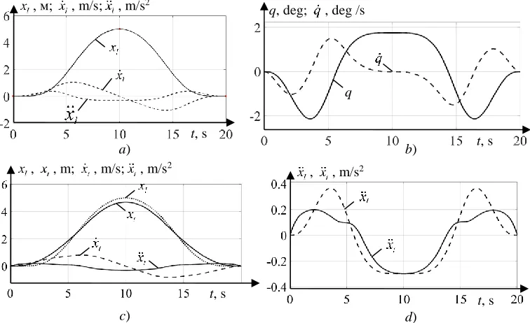
Figure 1 presents an example of the given trajectory of cargo xl(t) with two first derivatives,
as well as an optimized trajectory of suspension point movement synthesized according to the developed method. This optimized trajectory permits the cargo movement along a plane, thus simultaneously limiting angular sways.
Fig. 1. The predetermined cargotrajectory with two first derivatives (a), corresponding time dependences of the rope deflection angle and its first derivative, obtained by solving differential
equation (b), corresponding trajectory of a suspension point with the first two derivatives (c) and the joint schedule of cargo acceleration and suspension point (d)
The parameters of the linearized model of the dynamic system in the example took the following values: B = 5 kg ⸳ m2/s; m = 1000 kg; L = 10 m. Coordinates of the reference points of
the required trajectory: [t1; xlr1]=[0; 0]; [t2; xlr2]=[10; 5]; [t3; xlr3]=[20; 0]. All four first derivative
coordinates in all three reference points of the given trajectory of cargo took zero values, except , м; , m/s; , m/s2
t, s
q, deg; , deg /s
t, s
q
t, s
t, s , , m; , m/s; , m/s2
, , m/s2
a) b)
for the second derivative (acceleration) in the second reference point, the value of which was
2 lr
x =–0,3 m/s2.
The verification of the method and mathematical model was carried out in two stages, with the first stage involving the substitution of the synthesized trajectory of the suspension point movement in the form of a temporary dependence of the suspension point acceleration x tt( )) into
the original DE (1) and its subsequent solution by known numerical methods.
The maximum absolute error of the trajectory coordinate obtained when solving the original DE (1) by substituting the dependence shown in Fig. 1 into (1), d, with respect to the predetermined cargo trajectory presented in Fig. 1 (a), was 0.72 mm. The maximum time step in the process of integrating DE (5) and then DE (1) was equal to 0.001 s.
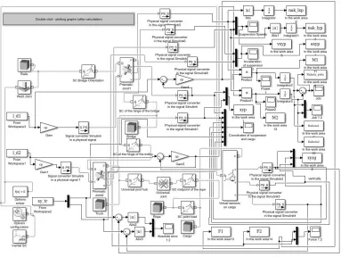
The second stage of verification used a spatial non-linear simulation mathematical BC model, performed in the multibody simulation environment Simscape Multibody of the Simulink MATLAB system (Fig. 2), as a reference model. This model, developed with the participation of the author and adapted to real nonlinear physical BC systems, is presented in (Shcherbakov et al. 2015).
Fig. 2. Spatial simulation mathematical model of the bridge crane with the cargo in the designations Simscape Multibody MATLAB Simulink, accepted as benchmark
Simscape Multibody, dependences of suspension point movements in two mutually perpendicular horizontal directions – xt1(t) and xt2(t) – were used.
The parameters of the dynamic system in both models (linearized and spatial non-linear) took the same values: B=5 kg⸳m2/s (for both directions of space); m=1000 kg; L=10 m.
At synthesis of a trajectory of movement of a point of a suspension in a direction xt1(t) when
the superposition of two flat movements was investigated, coordinates of reference points of the required trajectory of cargo were equal [t1; xlr1]=[0; 0]; [t2; xlr2]=[20; 10]. All four first derivative
coordinates in both reference points of the given trajectory of cargo took zero values.
During the synthesis of a trajectory of the suspension point movement in the second direction of space xt2(t), the coordinates of the reference points of the required cargo trajectory took the
values indicated for the first verification stage and corresponding to the flat trajectory shown in Fig. 1.
Synthesized by means of the linearized model in the form of a superposition of two plane trajectories [xt1(t); xt2(t)], the trajectory of the suspension point in the horizontal plane was
introduced input signals into the spatial simulation mathematical model. A spatial displacement was simulated. With the help of virtual oscilloscopes, the time dependences of the coordinates of the cargo were preserved, which were accepted as reference ones. Subsequently, a comparison of this spatial reference cargo trajectory in terms of each of two horizontal coordinates with the corresponding (given in a flat linearized statement) cargo trajectory (xl1(t) and xl2(t) accordingly)
was carried out. Time dependencies for the two current absolute errors of the two horizontal cargo coordinates Δ1(t) and Δ2(t), respectively, were calculated.
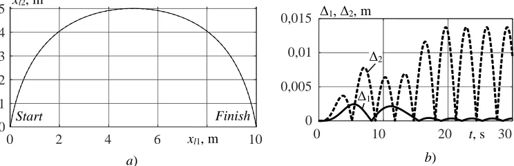
The results of the second stage of verification are shown in Fig. 3.
Fig. 3. The reference trajectory (–) and trajectory obtained as a result of a superposition of plane displacements of the cargo (---) on the plan view (a), and the corresponding time dependencies
of the absolute errors of the two horizontal coordinates of cargo (b)
The maximum absolute error on the coordinate № 2 (lateral direction), exceeding the maximum absolute error on the coordinate № 1 (see fig. 3, b) was Δ2max=0,0137 m, which can be
considered as an insignificant value when moving the cargo at distances exceeding a few meters.
The simulation of cargo movement using a reference spatial model shows the presence of minor residual decaying sways in the lateral direction after the cargo delivery to the target point, with their values not exceeding the magnitude of the corresponding absolute error (0.0137 m in the example).
0 2 4 6 10
1 2 3 4 5
0
a) b)
xl2, m
xl1, m
Start Finish
0 10 20 30
0 0,005 0,01 0,015
t, s Δ1, Δ2, m
Δ2
Therefore, further research should focus on developing methods for eliminating or reducing the residual decaying cargo sways caused by the linearization error.
It should also be noted, that increasing the movement time at fixed values of other trajectory parameters, significantly reduces the values of maximum absolute errors. For example, an increase in the travel time along the path shown in Fig. 3, a, by two times, i.e. from 20 to 40 s, leads to a decrease in the maximum absolute error on coordinate 2 to 0.53 mm.
4. Conclusion
The proposed methods allows a relatively simple synthesis of an optimum trajectory of the suspension point movement, which, with a high level of accuracy, ensures the given trajectory of cargo movement in the limited time. The methods with small computational complexity and high speed have been used, including numerical integration of DE and direct analytical calculations. These methods are not iterative in nature. The developed methods involve neither the complex mathematical calculations of the optimal control theory or the resource-intensive algorithms of multidimensional optimization. The non-iterative and single-entry nature of DE (5) integration makes it possible to consider any intermediate moment in the process of moving as new initial conditions, thereby allowing arbitrary changes in the unexplored site of the given trajectory of cargo directly during its realization. Since DE (1), i.e. the linearized equation of the pendulum system with one angular degree of freedom, is used for the derivation of DE (5), the application of this method is limited to relatively small deflection angles (less than ten degrees) of the BC cargo rope from the gravitational vertical. At the same time, it should be noted that, under real exploitation conditions, the angles of the BC cargo rope deflection from the gravitational vertical rarely exceed the maximal values by 4-5 degrees. In the future, the method can be used in BC automated control systems with a new function ensuring accurate movement of cargo on a given spatial trajectory in the mode of limiting unmanaged angular sways. Spatial sways of cargo at small corners of deviations of a cargo rope can be with sufficient accuracy represented as the superposition of flat sways in two perpendicular planes. Uncontrolled angular sways in the developed method are suppressed to a greater extent compared to similar known methods.
References
Abdel-Rahman EM, Nayfeh AH, Masoud ZN (2003). Dynamics and control of cranes: a review.
Journal of Vibration and Control, 9, 863-908.
Blackburn D, Singhose W, Kitchen J, Patrangenaru V, Lawrence J (2010). Command Shaping for Nonlinear Crane Dynamics, Journal of Vibration and Control, 16, 477-501.
Blekhman II (1994). Vibration mechanics, M.: Fizmatlit.
Chernousko FL, Akulenko LD, Sokolov B (1980). Control of oscillations, M.: Nauka.
Fang Y, Dixon WE, Dawson DM, Zergeroglu E (2003). Nonlinear coupling control laws for an underactuated overhead crane system. IEEE / ASME Trans. Mechatronics, Vol. 8, No. 3, 418-423.
Omar F, Karray F, Basir O, Yu L (2004). Autonomous overhead crane system using a fuzzy logic controller, Journal of vibration and control, Vol. 10, No. 9, 22-28.
Ridout AJ (1989). Anti-swing control of the overhead crane using linear feedback, Journal of Electrical and Electronics Engineering, Vol. 9, No. 1/2, 17-26.
Shchedrin AV, Serikov SA, Kolmykov VV (2007). Automatic system of soothing vibrations for overhead crane, Instruments and systems. Management, monitoring, diagnostics, 8, 13-17. Shcherbakov V, Korytov M, Sukharev R, Volf E (2015). Mathematical modeling of process
moving cargo by overhead crane, Applied Mechanics and Materials, 701-702, 715-720. Tolochko OI, Bazhutin DV (2010). A comparative analysis of methods of damping cargo