42
Journal of Membrane Science & Research
H I G H L I G H T S
A R T I C L E I N F O
G R A P H I C A L A B S T R A C T
A B S T R A C T
Fabrication and Modification of Thin-Film Composite Hollow Fiber NF Membranes
Zohreh Abolfazli, Ahmad Rahimpour
** Corresponding author at: Phone: +98 111 3220342, fax: +98 111 3220342 Received 2016-01-14
Revised 2016-05-31 Accepted 2016-06-07 Available online 2016-06-07
This study focuses on the preparation and modification of a thin-film composite (TFC) hollow fiber polyamide membrane fabricated by the interfacial polymerization of Piperazine (PIP) and trimesoyl chloride (TMC) on a porous polysulfone substrate. The effects of triethylenetetramine (TETA) and silica nanoparticles (SiO2) contents in the aqueous phase (as the additives) on the morphology and performance of the hollow-fiber composite membranes were studied. The morphologies, chemical composition and the surface image of membranes were investigated by using FTIR, SEM, AFM and contact angle analyzes. TETA resulted a more hydrophilic as well as lower surface roughness in the modified membranes. In addition, the active layer of the membranes had uniform, smooth and dense structures compared with the neat membrane (control sample). In case of the SiO2 nanoparticles, AFM images showed rougher surfaces in the modified membranes. However, the nanoparticles’ size is close to the membrane pore size. As a result, the silica particles block a few pure water channels of the membranes. The obtained results showed that the water flux increased with increasing the silica contents in the aqueous phase. Furthermore, the NaCl rejection increased by increasing the TETA concentration. This showed that adding optimal concentration of the both SiO2 and TETA in the aqueous phase would increase the both flux and rejection, as well as prepared appropriate hollow fiber TFC membrane. The hollow fiber composite membrane possessed a salt (NaCl) rejection of about 26 % and flux of about 31 L.m-2.h-1. Hollow fiber
Nanofiltration membrane Interfacial polymerization SiO2 nanoparticle
Triethylenetetramine
journal homepage: www.msrjournal.com Journal of Membrane Science and Research 3 (2017) 42-49
Department of Chemical Engineering, Babol Noshirvani University of Technology, Babol, Iran
K E Y W O R D S
Research Paper
© 2017 MPRL. All rights reserved.
E-mail address: ahmadrahimpour@yahoo.com; ahmadrahimpour@nit.ac.ir (A. Rahimpour) • Novel hollow fiber NF membranes were fabricated
• Effects of TETA and SiO2 nanoparticles on the separation performance of TFC membranes were studied • The optimized hollow fiber membranes had high water flux and reasonable salt rejection
• The hollow fiber had the separation characteristics of NF membranes
causing higher fluxes and lower operating pressures and are able to reject organic compounds and multivalent ionic salts [1, 2]. These advantages lead to a growing list of applications in the water purification processes, such as water softening [3, 4] and micro pollutant removal [5]. Industrially, the NF
1. Introduction
process is applied for separation of specific components and organics, such as pesticides [6, 7] and heavy metals removal [8, 9], dyes separation [10, 11], purification of pharmaceutical compounds [12] and food processing [13-15].
A composite membrane is provided by forming a nano-thin selective dense layer on a porous substrate. The top selective layer and bottom porous substrate of the composite membrane can be modified to maximize the overall membrane performance [16, 17]. Reports show that the performance of the NF membrane is determined by the chemical structure of the thin active layer, pore size and its distribution, film thickness, and the surface charge and its morphological features [18]. Among the methods for preparing TFC membranes, interfacial polymerization (IP) is the most effective one [19-20]. The IP technique is based on a polycondensation reaction between two monomers; that is, a poly functional amine and a poly functional acid chloride. The advantage of the IP method is that the reaction is self-inhibiting via passage of a limited supply of reactants through the already formed layer
[21]. Moreover, the thin layer can be optimized for a particular function by varying the monomer concentration in each solution, monomer ratios and reaction time of the interfacial polymerization [22-28].
The main attempt in optimal design of membrane processes is to create maximum permeate flow while having maximum solute rejection, with minimum capital and operating costs, as well [29-31]. Today, the main module geometries used are spiral-wound or tubular modules. The advantages of spiral modules are the large surface area of the membrane per m3 and the
low module cost. However, they are extremely susceptible to the floating matter, have high energy losses caused by friction in the spacers and it is not possible to be reverse flushed [32]. Tubular modules do not require strong pre-treatment and back flushing is possible but they have low packing density and are expensive [33]. In consideration of the fact that membranes in hollow fiber (HF) form have some advantages over membranes in flat-sheet configuration, such as high surface to volume ratio, no require of feed and permeate spacers as well as less demand for pretreatment and maintenance, give a better packing density than the tubular module and allows a less demanding pretreatment and maintenance than that of the spiral wound module, studies have been focused on the development and application of NF membranes in hollow fiber configuration, recently [11].
It is also reported in the literature that an optimized hollow fiber NF module would give a 100% increase in performance compared to an optimized spiral-wound module [34]. This module configuration would be a solution for the treatment of low quality water sources by direct capillary nanofiltration.
The aim of this study was to investigate the effect of adding silica nanoparticles and TETA on the permeation performance and morphology of thin-film composite hollow fiber membranes. In this study, Polysulfone (PSF) hollow fiber UF membrane was used as a support layer. Trimesoyl chloride (TMC) and Piperazine (PIP) were used as monomers for IP reaction. The hollow fiber polypiperazine-amide TFC-NF membranes were prepared by adding TETA, silica nanoparticles (SiO2) and both of them, in aqueous phase
of interfacial polymerization reaction to achieve high permeable composite membrane.
2. Experimental
2.1. Materials
Polysulfone (PSf, Udel P3500, Solvay Polymers), and N-methyl-2-pyrrolidinone (NMP, 99.8%, Merck) were used as the base polymer and solvent for preparation of UF hollow fiber membranes, respectively. Also, polyethylene glycols (PEG, Mw= 1000 g/mol), Lithium chloride (LiCl),
glycerol and Triton X-100 supplied from Merck were used as additive. Trimesoyl chloride (TMC, Sigma-Aldrich) and Piperazine (PIP, Merck) were used for the preparation of polyamide active layer on the hollow fiber substrate. SiO2 nanoparticles and triethylenetetramine (TETA) were
purchased from US Research Nanomaterial (15–20 nm, 170–200 m2/g) and
Sigma-Aldrich, respectively.
2.2. Fabrication of PSF hollow fiber support membrane
To prepare the dope solution, 18% (w/w) of PSF with PEG, LiCl, Triton X-100 and glycerol as additives were well-mixed in the presence of NMP as solvent in a glass flask under magnetic stirring. The dope solution left aside for at least 12 h to remove air bubbles. Hollow fiber membranes were spun using the dry/wet spinning technique. The dope solution was loaded into a
reservoir and forced to the spinneret using pressurized nitrogen. The spinneret had 0.5 mm inner diameter and 1 mm outer diameter. The spinning conditions of the fabricated hollow fiber PSF membranes were summarized in Table 1. The bore liquid and the external coagulant were tap water.
Table 1. Spinning conditions of the hollow fiber membranes.
Spinning parameter Operating condition
Nitrogen extrusion pressure 50 Kpa
Bore fluid Distillated water
Bore fluid flow rate 0.35 l/h
External coagulant Tap water
External coagulant temperature 25 °C
Air gap distance 1 cm
2.3. Preparation of TFC membranes
Thin-film composite hollow fiber membranes were prepared by interfacial polymerization of Piperazine in aqueous phase with TMC in organic phase (i.e. n-hexane). The concentration of additives in the aqueous phase are given in Table 2. The PSF hollow fiber support membrane was submerged into the aqueous phase for 90 s. Subsequently, the membrane was taken out to drain off the excess monomers for 1 min. The amine saturated membrane was again immersed into the organic phase containing 0.5% (w/v) TMC in n-hexane where the conventional IP reaction took place. Afterward, the membrane was taken out and air-dried at 70 °C for 4 min. The dipping process had been carried out such a way that only the external surface has come in contact with reactants to form polyamide skin layer.
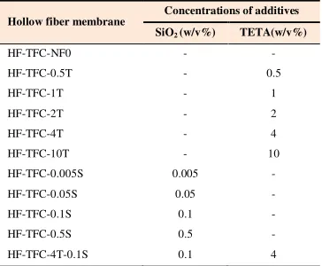
Table 2. The concentrations of additives in the aqueous phase to prepare thin layer.
Hollow fiber membrane
Concentrations of additives
SiO2 (w/v%) TETA(w/v%)
HF-TFC-NF0 - -
HF-TFC-0.5T - 0.5
HF-TFC-1T - 1
HF-TFC-2T - 2
HF-TFC-4T - 4
HF-TFC-10T - 10
HF-TFC-0.005S 0.005 -
HF-TFC-0.05S 0.05 -
HF-TFC-0.1S 0.1 -
HF-TFC-0.5S 0.5 -
HF-TFC-4T-0.1S 0.1 4
2.4. Characterization of membranes
The water contact angle of hollow fiber membranes was measured using a OCA 15 plus Tensiometer from Data physics Co. The hollow fiber with an effective length of 5 mm was immersed in ultra-pure water and the advancing contact angle was calculated with the aid of the computer software.
FTIR analysis (WQF-510A FT-IR spectrometer, RAYLEIGH, China) was used to confirm the interfacial polymerization mechanism.
The morphology of hollow fiber membranes was observed by a scanning electron microscope (SEM, EM-3200- KYKY Co., China).
Z. Abolfazli and A. Rahimpour / Journal of Membrane Science and Research 3 (2017) 42-49
2.5. Nanofiltration experiments
The permeation properties of membranes were investigated with a cross-flow hollow fiber filtration setup. The module consisted of two fibers with a length of 24 cm. The shell sides of the two ends of the bundles were glued into two tees using a normal-setting epoxy resin. For each experiment, the solution containing 2000 ppm of NaCl was used as feed at pressure of 5 bar, temperature of 25 0C for evaluating the membrane performance during 30
min. The flux (J), through the membrane, may be described by:
t A
V J
∆
= (1)
where V is the volume of permeate, A is the membrane surface area and ∆t is filtration time.
The solute rejection R (%) was calculated by the following equation
100 ) 1 (
(%)= − ×
C
C
feed permeate
R (2)
where Cpermeate and Cfeed are the NaCl concentrations in permeate and feed
solution.
3. Results and discussion
3.1. Membrane surface properties
The influences of TETA as additives in aqueous phase on the contact angle are presented in Figure 1. The surface contact angle of PSF membrane was decreased by adding of this hydrophilic monomer (TETA) in the aqueous phase. This demonstrates that a more hydrophilic surface is obtained by adding of TETA in the aqueous phase. TETA is a well-known hydrophilic monomer with amine (N–H) functional group (see Figure 2). The higher membranes’ hydrophilicity with addition of TETA compared to the membrane prepared without additives can be attributed to the hydroxyl group (O–H) of TETA that remained in the membrane structure.
FTIR spectra were used to investigate the changes in the chemical composition of the membrane surface. The spectra from PSF UF membrane and thin film composite membranes prepared with 4 wt.% TETA dissolved in the aqueous phase are shown in Figure 3. Obtained FTIR spectra shows the changes in the membrane composition.
In Figure 3a, the peak at 1050 cm-1 is assigned to symmetric and
asymmetric S=O band of polysulfone. Two peaks at 1511 and 1596 cm-1 are assigned to asymmetric aromatic bands of C=C groups, that are the special bands of the polysulfone. In Figure 3b, A strong band at 1670 cm-1 appears,
which is assigned to C=O group in amide functional group that indicates that the interfacial polymerization successfully occurred. Two peaks at 1595 and 2981 cm-1 are assigned to N-H band. In addition to, the peek at 3100 cm-1 refers to –COOH band [36, 37].
The effect of silica in the aqueous phase on the contact angle of top surface of the membranes is presented in Figure 4. When concentration of silica in the casting solution is increased up to 0.1 wt.%, the contact angle of the membrane is strongly decreased. This trend could be attributed to the hydrophilicity of silica nanoparticle remained in the membrane structure. Also, the chemical composition of the TFC membrane surfaces is investigated by the FTIR and the obtained results are presented in Figure 3c. The FTIR spectrum indicated that the interfacial polymerization occurred due to the strong bond at 1731 cm-1, which is characteristic band of the C=O [38]. The bands at 694.2 and 1014 cm-1 suggest the stretching vibration and anti-stretching vibration of Si-O band.
In Figure 4, the highest contact angle was obtained for PSF membrane
without addition of silica or TETA in the aqueous phase. This indicates the lowest hydrophilicity. The membrane prepared with 0.1 wt.% SiO2 and 4
wt.% TETA in the aqueous phase exhibited lowest contact angle indicating highest hydrophilicity. The strong change in membranes’ hydrophilicity with both TETA and SiO2 can be ascribed by the carboxyl and amide polar groups
which are strongly hydrophilic. As shown in Figure 3d, compared with the PSF membrane, the FTIR spectra of the TFC membrane with 0.1 wt.% SiO2
and 4 wt.% TETA in the aqueous phase, exhibited same signals at 1596.7 and 2980 cm-1 to N-H bands and 1014.3 cm-1 to Si-O band.
Fig. 1. Contact angle of neat and TETA modified membranes.
Fig. 2. TETA chemical structure.
Fig. 3. FTIR spectra: (a) UF membrane, (b) TETA/polypiperazine-amide HF TFC NF membrane, (c) silica/polypiperazine-amide HF TFC NF membrane, and (d) TETA/silica/polypiperazine-amide HF TFC NF membrane.
Fig. 4. Contact angle of neat and Silica modified membranes.
3.2. Membrane morphology
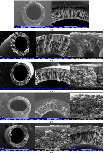
The fast solvent/non-solvent exchange takes place across the interface of casting film and non-solvent immediately after immersion of the casting film into the water bath. This is combined with the large repulsive forces between polymer (PSF) and water (water is a very powerful non-solvent for PSF) leading to immediate precipitation of the polymer at the interface. As a result, an asymmetric membrane with a thin skin layer and large fingerlike pores in the sub-layer is formed. This is clearly exemplified by the SEM image (Figure 5a) which shows the large pores in the sub-layer of the membrane prepared
from the casting solution. According to the Figure 5b, the reaction between the TMC and the PIP leads to formation of a thin layer. The cross sectional morphologies of the membranes prepared with the addition of 4 wt.% TETA are different from the original NF membrane (Figure 5c). The active skin layer in this membrane has a uniform, smooth and dense structure. The cross sectional morphologies of the membranes prepared with the addition of 0.1 wt.% SiO2 are shown in Figure 5d. The thickness of the formed thin layer
containing both TETA and SiO2 particles is higher than that of other
membranes and is clearly observed in Figure 5e.
(a)
(b)
(c)
(d)
(e)
Z. Abolfazli and A. Rahimpour / Journal of Membrane Science and Research 3 (2017) 42-49
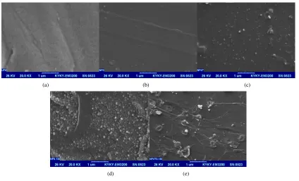
The surface crosslinking reaction can influence the external membrane surface [39]. Figure 6 shows the morphologies for external surface of the PSF hollow fiber UF membranes and the composite membranes prepared without additives and with TETA and SiO2, i.e. both of them in aqueous phase.
Formation of a thin layer on the membrane support results in a wholly shrinkage surface which causes a superior separation properties.
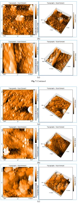
In order to analyze the surface topology of the polyamide coated membranes in detail, the membranes’ surface were scanned by the AFM.
Figures 7-9 showed the AFM images as well as roughness analysis by taking
a horizontal section in the image frame for samples. In the images, the brightest areas indicate the highest points of the membrane surface and the dark regions show valleys or pores. Figure 7 shows the surface AFM images of the PSF membranes prepared with various TETA concentration in the aqueous phase. It visually seems that the membranes roughness prepared with TETA is lower than that of the original PSF NF membrane. Also, decreasing roughness by increasing TETA concentration could be due to expansion of the IP reaction, possibly leading to the formation of the polyamide smoothly active layer. In this condition, decreasing the roughness might cause lower fouling. Table 3 demonstrates a decreasing trend in roughness with addition of additive. As can be seen in Figure 8, images recorded for composite membranes confirm that SiO2 nanoparticles were successfully coated onto the
membrane and produced rougher surfaces. Increasing of surface roughness parameters was due to disturb the unity of the polymer chains in membrane structure. This could be due to aggregation of nanoparticles, particularly in high concentrations [40]. In Figure 9, the AFM images of PSF membranes’ surface prepared with both of TETA (4%) and SiO2 (0.1%) are presented. As
could be observed, the roughness was decreased because of sandwiching nanoparticles between layers.
Table 3. The mean roughness (Ra) of the prepared hollow fiber membranes.
Sq (nm)
Sa (nm)
Sz (nm)
Membrane
43.115 28.628
354.17 HF-TFC-NF0
27.962 22.722
213.94 HF-TFC-1T
25.450 18.762
192.31 HF-TFC-4T
9.689 7.385
86.441 HF-TFC-0.05S
24.099 18.988
163.83 HF-TFC-0.1S
15.925 11.759
138.48 HF-TFC-4T-0.1S
(a) (b) (c)
(d) (e)
Fig. 6. Surface SEM images: (a) PSF sublayer hollow fiber membrane, (b) polypiperazine-amide HF TFC NF membrane( HF-TFC-NF0), (c) TETA/polypiperazine-amide HF TFC NF membrane (HF-TFC-4T), (d) silica/polypiperazine-amide HF TFC NF membrane (HF-TFC-0.1S), and (e) TETA/silica/polypiperazine-amide Hf TFC NF membrane (HF-TFC-4T-0.1S).
(a)
Fig. 7. Surface morphologies AFM images: (a) polypiperazine-amide HF TFC NF membrane (HF-TFC-NF0), (b) TETA/polypiperazine-amide HF TFC NF membrane (HF-TFC-1T) and (c) TETA/polypiperazine-amide HF TFC NF membrane (HF-TFC-4T).
(b)
(c)
Fig. 7. Continued
(a)
(b)
(c)
Z. Abolfazli and A. Rahimpour / Journal of Membrane Science and Research 3 (2017) 42-49
Fig. 9. Surface morphologies AFM images of TETA/silica/polypiperazine-amide HF TFC NF membrane (HF-TFC-4T-0.1S).
3.3. Membrane performance
The values of the NaCl rejection and the water permeability are presented
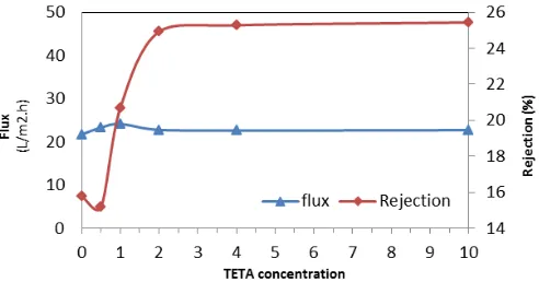
in Figure 10, for various TETA concentrations. From Figure 10, it can be seen
that the salt rejection increased from 15.17 to 25.44% with increasing the TETA concentration from 0.5 to 10% (w/v). This increase could be attributed to the expansion of the polymerization reaction in the presence of TETA and denser polyamide active layer (Figure 5). In fact, with the addition of TETA to the aqueous solution due to the expansion of polymerization reaction from third sides, polyamide active layer with more density and hydrophilicity was formed, which can lead to increase the flux. Also, from the AFM images (Figure 7), it can be observed that the surface roughness is reduced. As a result, it can be concluded that lower surface roughness can lead to lower fouling tendency, which this can be considered as a flux increasing reason. Increasing the TETA concentration was continued from 1% to 10% in the aqueous solution, which leads to flux decreased slightly and then not showed much change. To explain the flux decline, it can be concluded, though adding TETA, hydrophilic amide groups and free amino groups on the membrane surface increased, but increased membrane density is dominated by the increased hydrophilicity, which eventually would lead to a slight decrease in the flux. Finally, according to the rejection rate and the permeate flux, the concentration of 4% TETA, which have relatively high rejection and acceptable flux, was selected as the optimum concentration in order to get stable separation performance in further experiments.
Fig. 10. Effect of TETA concentrations in the aqueous phase on flux and NaCl rejection of membranes.
As shown in Figure 11, when the silica concentration increased from 0 to 0.1% (w/v), the NaCl rejection increased from 14.59 to 19.94% and then decreased down to 17.69% when the concentration continued to 0.5% (w/v). Rejection decline can be explained by the fact of excessive concentrations of silica nanoparticles that caused accumulations occur in some membrane surface areas and inhibit reactions between the organic and aqueous phases and consequently the crosslinking not completely established. The water flux increased from 21.7 up to 39.68 L.m−2.h−1 with the silica concentration
increasing from 0 to 0.005% (w/v) and then decreased down to 34.50 L.m−2.h−1, when the concentration continues to 0.5% (w/v). The presence of silica nanoparticles in the aqueous solution affected on the IP reaction and
increased the crosslinking. Secondly, the presence of nanoparticles in the formation of the polyamide layer increased the membrane hydrophilicity. Increasing hydrophilicity caused the water molecules to pass through the membrane at higher speeds. Silica nanoparticles affected on the surface polymerization and changed the crosslinking conditions. Also, due to mixture miscibility of organic and aqueous phases in the polymerization process, its variability was greater [41, 42]. With continuing increase of the silica content from 0.1 to 0.5%, the active layer is easier to fall-off from the supporting membrane after the filtration experiment [43]. In fact, the flux decline is mainly due to a small amount of silica attached to the membrane pore. The size of nanoparticles is close to the membrane pore size, so the silica will block a small amount of pure water channels of membrane [40, 43].
Fig. 11. Effect of silica concentrations in the aqueous phase on flux and NaCl rejection of membranes.
4. Conclusions
Polyamide polysulfone hollow fiber composite nanofiltration (NF) membranes were prepared by interfacial polymerization process. The polypiperazine-amide TFC NF membrane was prepared under the optimum condition: 3% (w/v) PIP in the aqueous phase; 0.5% TMC in the organic phase; reaction time of 60 s and curing temperature at 70 °C for 4 min. Under these conditions, the effects of additives (TETA, SiO2 and both of them) in
the aqueous phase on the performance and structure of hollow fiber composite membrane were discussed. The experimental results showed that the structure and performance of the composite membrane can be effectively controlled by adjusting the concentration of additives. The membranes containing TETA showed high rejection. After addition of silica sol in the aqueous phase, the water flux of the resulting membrane changed slightly, but the NaCl rejection increased.
5. References
[1] L. Lianchao, W. Baoguo, T. Huimin, C. Tianlu, X. Jiping, A novel nanofiltration membrane prepared with PAMAM and TMC by in situ interfacial polymerization on PEK-C ultrafiltration membrane, J. Membr. Sci. 269 (2006) 84–93.
[2] L. Li, S. Zhang, X. Zhang, Preparation and characterization of poly(piperazineamide) composite nanofiltration membrane by interfacial polymerization of 3,3’,5,5’-biphenyl tetra acyl chloride and Piperazine, J. Membr. Sci. 335 (2009) 133–139.
[3] D. Nanda, K.L. Tung, Y.L. Li, N.J. Lin, C.J. Chuang, Effect of PH on membrane morphology, fouling potential, and filtration performance of nanofiltration membrane for water softening, J. Membr. Sci. 349 (2010) 411–420.
[4] M. Homayoonfal, A. Akbari, M.R. Mehrnia, Preparation of polysulfone nanofiltration membranes by UV-assisted grafting polymerization for water softening, Desalination 263 (2010) 217–225.
[5] S. Top, E. Sekman, S. Hosver, M.S. Bilgili, Characterization and electrocaogulative treatment of nanofiltration concentration of a full-scale landfill leachate treatment plant, Desalination 268 (2011) 158–162.
[6] Y.M. Zhang, K. Pagilla, Treatment of Malathion pesticide wastewater with nanofiltration and photo-Fenton oxidation, Desalination 263 (2010) 36–44. [7] Q. Yang, Y.J. Hu, L. Xue, Back-propagation model for nanofiltration process
simulation in pesticide wastewater treatment, Adv. Mater. Res. 168 (2010) 404– 407.
[8] F.L. Fu, Q. Wang, Removal of heavy metal ions from wastewaters: a review, J. Environ. Manage. 3 (2011) 407–418.
[9] J. Llanos, R. Camarillo, A. Pérez, P. Cañizares, M.A. Rodrigo, Costs estimation of an integrated process for the treatment of heavy-metal loaded aqueous effluents, J. Appl. Electrochem. 41 (2011) 1099–1107.
[10] S.C. Yu, M.H. Liu, M. Ma, M. Qi, Z.H. Lv, C.J. Gao, Impacts of membrane properties on reactive dye removal from dye/salt mixtures by asymmetric cellulose acetate and composite polyamide nanofiltration membranes, J. Membr. Sci. 350 (2010) 83–91.
[11] S.C. Yu, Z.W. Chen, Q.B. Cheng, Z.H. Lv, M.H. Liu, C.J. Gao, Application of thin film composite hollow fiber membrane to submerged nanofiltration of anionic dye aqueous solutions, Sep. Purif. Technol. 88 (2012) 121–129.
[12] M.G. Buonomenna, L.C. Lopez, M. Davoli, P. Favia, R. Agostino, E. Drioli, Polymeric membranes modified via plasma for nanofiltration of aqueous solution containing organic compounds, Micropor. Mesopor. Mat. 120 (2009) 147–153. [13] K. Walha, R. B. Amar, A. Massé, P. Bourseau, M. Cardinal, J. Cornet, C. Prost, P.
Jaouen, Aromas potentiality of tuna cooking juice concentrated by nanofiltration, Food Sci. Technol. Int. 44 (2011) 153–157.
[14] B.D. Reinoso, A.Moure, H. Domínguez, J.C. Parajó, Ultra- and nanofiltration of aqueous extracts from distilled fermented grape pomace, J. Food Eng. 91 (2009) 587–593.
[15] J. Q. Liu, Z. L. Xu, X. H. Li, Y. Zhang, Y. Zhou, Z. X. Wang, X. J. Wang, An improved process to prepare high separation performance PA/PVDF hollow fiber composite nanofiltration membranes, Sep. Purif. Technol. 58 (2007) 53–60. [16] A.P. Rao, S.V. Joshi, J.J. Trivedi, C.V. Devmurari, V.J. Shah,
Structure-performance correlation of polyamide thin film composite membranes: effect of coating conditions on film formation, J. Membr. Sci. 211 (2003) 13-24.
[17] B. Tang, Z. Huo, P. Wu, Study on a novel polyester composite nanofiltration membrane by interfacial polymerization of triethanolamine (TEOA) and trimesoyl chloride (TMC) I. Preparation, characterization and nanofiltration properties test of membrane, J. Membr. Sci. 320 (2008) 198–205.
[18] H. Wang, Q. Zhang, S. Zhang, Positively charged nanofiltration membrane formed by interfacial polymerization of 3,3’,5,5’-biphenyl tetra acyl chloride and Piperazine on a poly (acrylonitrile) (PAN) support, J. Membr. Sci. 378 (2011) 243–249. [19] I. Pinnau, B.D. Freeman, Membrane formation and modification, 2000. In: ACS
Sym. Series 744, American Chemical Society, Washington, DC.
[20] A.P. Rao, N.V. Desai, R. Rangarajan, Interfacially synthesized thin film composite RO membranes for seawater desalination, J. Membr. Sci. 124 (1997) 263–272. [21] M. Mulder, Basic principles of membrane technology, 2nd ed., Kluwer Academic
Publishers, Dordrecht, The Netherlands, 2000.
[22] U. Razdan, S.S. Kulkarni, Nanofiltration thin-film-composite polyesteramide membranes based on bulky diols, Desalination 161 (2004) 25–32.
[23] A.W. Mohammad, N. Hilal, M.N. Abu Seman, A study on producing composite nanofiltration membranes with optimized properties, Desalination. 158 (2003) 73– 78.
[24] M. N. Abu Semana, M. Khayetb, N. Hilal, Nanofiltration thin-film composite
polyester polyethersulfone-based membranes prepared by interfacial
polymerization, J. Membr. Sci. 348 (2010) 109–116.
[25] V. Freger, Nanoscale heterogeneity of polyamide membranes formed by interfacial polymerization, Langmuir. 19 (2003) 4791–4797.
[26] J. Petersen, Composite reverse osmosis and nanofiltration membranes. J. Membr. Sci. 83 (1993) 81–150.
[27] R. Nadler, S. Srebnik, Molecular simulation of polyamide synthesis by interfacial polymerization, J. Membr. Sci. 315 (2008) 100–105.
[28] H. Zhu, A. Szymczyka, B. Balanneca, On the salt rejection properties of nanofiltration polyamide membranes formed by interfacial polymerization, J. Membr. Sci. 379 (2011) 215–223.
[29] S.S. Sablani, M.F.A. Goosen, R. Al-Belushi, M. Wilf, Concentration polarization in ultrafiltration and reverse osmosis: a critical review, Desalination (2001) 141-269. [30] F. Maskan, D. E. Wiley, L. P. M. Johnston, Optimal design of reverse osmosis
module networks, AIChE J. 46 (2000) 946-954.
[31] C. Cheng, L. Ma, D. Wu, J. Ren, W. Zhao, J. Xue, S. Sun, C. Zhao, Remarkable pH-sensitivity and anti-fouling property of terpolymer blended polyethersulfone hollow fiber membranes, J. Membr. Sci. 378 (2011) 369– 381.
[32] H. Futselaar, H. Schonewille, W. van der Meer, Direct capillary nanofiltration- A new high-grade purification concept, Desalination 145 (2002) 75–80.
[33] M. Frank, G. Bargeman, A. Zwijnenburg, M. Wessling, Capillary hollow fiber nanofiltration membranes, Sep. Purif. Technol. 22–23: (2001) 499-506.
[34] W.G. J. van der Meer, J.C. van Dijk, Theoretical optimization of spiral-wound and
capillary nanofiltration modules, Desalination. 113 (1997) 129–146.
[35] Y. Mansourpanah, S.S. Madaeni, A. Rahimpour, Fabrication and development of interfacial polymerized thin-film composite nanofiltration membrane using different surfactants in organic phase; study of morphology and performance, J. Membr. Sci. 343 (2009) 219–228.
[36] Y. Mansourpanah, E. Momeni Habili, Preparation and modification of thin film PA membranes with improved antifouling property using acrylic acid and UV irradiation, J. Membr. Sci. 430 (2013) 158-166.
[37] J. Wang, Z. Fang, A. Gu, L. Xu, F. Liu, Effect of amino-functionalization of multi-walled carbon nanotubes on the dispersion with epoxy resin matrix, J. Appl. Polym. Sci. 100 (2006) 97–104.
[38] S. Qiu, L.G. Wu, X.J. Pan, L. Zhang, H.L. Chen, C.J. Gao, Preparation and properties of functionalized carbon nanotube/PSF blend ultrafiltration membranes, J. Membr. Sci. 342 (2009) 169–172.
[39] H.A. Tsai, L.D. Li, K.R. Lee, Y.C. Wang, C.L. Li, J. Huang, J.Y. Lai, Effect of surfactant addition on the morphology and pervaporation performance of asymmetric polysulfone membranes, J. Membr. Sci. 176 (2000) 97–103.
[40] S. Pourjafar, A. Rahimpour, M. Jahanshahi, Synthesis and characterization of
PVA/PES thin film composite nanofiltration membrane modified with TiO2
nanoparticles for better performance and surface properties, J. Indust. Eng. Chem. 18 (2012) 1398–1405.
[41] H. Wu, B. Tang, P. Wu, Optimizing polyamide thin film composite membrane covalently bonded with modified mesoporous silica nanoparticles, J. Membr. Sci. 428 (2013) 341–348.
[42] C.K. Kim, J.H. Kim, I.J. Roh, J.J. Kim, The changes of membrane performance with polyamide molecular structure in the reverse osmosis process, J. Membr. Sci. 165 (2000) 189–199.