Spectrum Sensing and Throughput Analysis for
Full-Duplex Cognitive Radio with Hardware
Impairments
A. Nasser
123 ∗, A. Mansour
1, K. C. Yao
2, H. Abdallah
3, A. Abdul Ghani
3 1LABSTIC C UMR CNRS 6285, ENSTA Bretagne, 2 Rue François Verny, 29806 Brest , France2LABSTIC C UMR CNRS 6285, Univ ersité de Bretagne Occiden tale, 6 Av. Le Gorg eu, 29238 Brest , France 3Computer Science Departmen t, American Univ ersity of Culture and Educa tion, Beirut , Lebanon
Abstract
In Full-d uplex Cognitiv e Radios, the silen t period of the Secondary User (SU) during the Spectrum Sensing can be elimina ted by appl ying the Self -Interf erence Cancella tion (SIC). Due to the channel estima tion error and the hardw are imperf ections (the Phase Noise and the Non-Linear Distortion (NLD)) SIC is not perf ectl y perf ormed and resul ts in the Resid ual Self -Interf erence (RSI) which affects the Spectrum Sensing reliability . In this paper , the effect of RSI on Spectrum Sensing is anal yticall y deriv ed by expressing the detection (pd)
and false alarm (pf a) probabilities under FD in terms of the ones under Half -Duplex (HD) (where SU shoul d
remain silen t during the Spectrum Sensing period). In addition, an algorithm is proposed to suppress the NLD and improv es the Spectrum Sensing perf ormance. Hereinafter , the SU throughput under FD is anal ysed comparing to HD by deriving the upper and lower bounds to be respected by pf aand pdrespectiv ely in order to make FD beneficia rela tiv e to HD.
Receivedon 30 November 2016; accepted on 07 May 2017;published on 31 May 2017
Keywords: Cognitiv e Radio, Full-Duplex, Self -Interf erence Cancella tion, Non-Linearity Distortion, Spectrum Sensing,
Throughput Anal ysis
Copyright © 2017 A. Nasser etal., licensed to EAI. This is an open access article distributed under the terms of the
Creative Commons Attribution license (http://creativecommons.org/licenses/by/3.0/), which permits unlimited
use, distribution and reproduction inanymedium solongastheoriginal workisproperlycited. doi:10.4108/eai.31-5-2017.152556
1. Introduction
Recen tly, the Full Duplex (FD) transmission has been introd uced in the context of Cognitiv e Radio (CR) to enhance the Data-Ra te of the Secondary (unlicensed) User (SU). In FD systems, SU can simultaneousl y transmit and sense the channel. In classical Half Duplex (HD) systems, the SU shoul d stop transmitting in order to sense the sta tus of the Primary (licensed) User (PU). Recen t adv ancemen ts in the Self -Interf erence Cancella tion (SIC) make the applica tion of FD in CR possible. Due to many imperf ections, a perf ect elimina tion of the self -interf erence cannot be reached in real world applica tions [2, 3]. In CR, the SU makes
HThis paper is presen ted in part at the 11th Interna tional Conference
on Cognitiv e Radio Orien ted Wireless Netw orks (CROWNCOM 2016) [1]
∗Corresponding author Email: abbas.nasser@univ -brest.fr
a decision on the PU sta tus using a Test Statistic [4–
6]. This Test Statistic depends on the PU signal and the noise. Any resid ual interf erence from the SU signal can affect the Test Statistic norm and leads to a wrong decision about the presence of PU.
In wireless systems, the FD is considered as achiev ed if the Resid ual Self Interf erence (RSI) pow er becomes lower than the noise lev el. For tha t an importan t SIC gain is required (around 110 dB for a typical WiFi system [2]). This gain can be achiev ed using a passiv e suppression and an activ e cancella tion. The passiv e suppression is rela ted to many factors tha t red uce the Self Interf erence (SI) such as the transmission direction, the absorption of the metals and the distance betw een the transmitting antenna, Tx, and the receiv e antenna,
Rx. The activ e cancella tion red uces the Self -Interf erence
(SI) by using a copy of the known transmitted signal. The estima tion of channel coefficien ts becomes an essen tial factor in the activ e cancella tion process. Any
error in the channel estima tion leads to decreasing the SIC gain.
Experimen tal resul ts show tha t hardw are imperf ections such as the non-linearity of amplifier and the oscilla tor noise are the main limiting perf ormance factors [2, 7–
9]. Theref ore, the SIC shoul d also consider the receiv er imperf ections. The authors of [2] modify their previous method of [10] to estima te the channel and the Non-Linearity Distortion (LND) of the receiv er Low -Noise Amplifie (LNA). Their method requires tw o training symbol periods. During the firs period, the channel coefficien ts are estima ted in the presence of the NLD. The non-linearity of the amplifie is estima ted in the second period using the already estima ted channel coefficien ts. It is worth men tioned tha t the estima tion of the NLD par ameters in the second phase depends on the one of the channel coefficien ts done in the firs phase. However the estima tion of the channel coefficien ts in the firs phase can be depending on unknown NLD par ameters. To solve the previous dilemma, we propose hereinafter an estima tion method of the NLD in such way tha t the estima tion of the channel cannot be affected by the NLD.
The works of [11–16] deal with the applica tion of FD in CR. In [11–13, 15], the RSI is modeled as a linear combina tion of the SU signal without considering hardw are imperf ections. In [13, 16] the Energy Detection (ED) is studied in a FD mode and the probability of detection, (pd), and false alarm, pf a, are
found anal yticall y. According to our best knowledg e, there is no anal ytic rela tionship betw een the RSI,pdand
pf afor both HD and FD mode.
Further , due to the RSI, pd and pf aare highl y affected.
This fact impacts neg ativ ely the SU throughput. In some circumstances, the SU throughput under HD can be higher than the one of FD. This can be occurred when the false alarm rate is high. On the other hand, PU transmission is consider abl y disturbed by the SU activities when the detection rate becomes low. For tha t reason, upper bound of false alarm rate and lower bound of detection rate are importan t in order to be abided by SU in FD mode in order to enhance the throughput without increasing the interf erence rate to PU comparing to HD mode.
This paper deals with the Spectrum Sensing in real world applica tions. At firs , we anal yticall y determine the impact of the RSI pow er on the detection process. For tha t objectiv e, we deriv e a rela tion betw een the RSI pow er, the probabilities of detection and false alarm under HD and FD modes. Secondl y, we anal yse the NLD impact on the channel estima tion and the Spectrum Sensing Perf ormance. Hereinafter , novel algorithms are proposed to suppress the NLD of LNA.
In addition, the effect of FD mode on the SU throughput is compared to the HD mode. As the throughput is rela ted to pd and pf a, the upper bound of false
alarm rate and the lower bound of the detection rate are deriv ed. These tw o bounds char acterize the required limit in FD in order to enhance the SU throughput comparing to HD without making an additional interf erence to PU.
The rest of this paper is presen ted as follows, in section (2), an overview of OFDM receiv er is presen ted by focusing on the circuit imperf ections. The Spectrum Sensing hypothesis in Full-Duplex Cognitiv e Radio is presen ted in section (3), where the effect of RSI is anal ysed anal yticall y. In section (4), an algorithm of the NLD mitig ation in RF domain is proposed with its corresponding numerical resul ts. Throughput anal ysis in terms of detection and false alarm probabilities is presen ted in section (5). At the end, section (6) concl udes the work by providing new perspectiv es.
Throughout this paper , uppercase letters represen t frequency -domain signals and lower-case letters repre-sent signals in time-domain.
2. Receiver chain Imperfection Analysis
In this section, we anal yse the imperf ections in a classical OFDM receiv er. By referring to figur (1), which represen ts a typical Ordinary Chain (OC) of an OFDM receiv er block-diagr am, the SU signal receiv ed atRxis modelled as:
y(t) =h(t)∗s(t) exp (j2πfct) (1)
where h(t) is the channel effect betw een Txand Rxand
∗stands for the convolution oper ator. After tha t,y(t) is
amplifie using the LNA which introd uces a NLD. The output of LNA can be modelled in a gener al form as a pol ynomial of odd degrees:
ya(t) =
∞
X
i=0
a2i+1y2i+1(t) (2)
The firs coefficien ta1, stands for the linear componen t which represen ts the amplifie signal. The other coefficien ts (a2i+1, i≥2) stand for the non-linear
componen ts contributing in NLD. Since the higher componen t are of negligible pow er, the NLD of the output of the LNA is limited to the third order pol ynomial output:
ya(t) =a1y(t) +a3y3(t) (3)
In digital domain, ya(n) can be expressed as follows
[3,17]:
ya(n) =a1y(n) +a3y(n)|y(n)|2 (4)
After the amplific tion process, the receiv ed signal is down-con verted to the base-band form. As shown in figur (1), the oscilla tor can introd uce a multiplica tiv e
noise exp jφ(t) .
After converting to the base-band, the Anal og-to-Digital Converter (ADC) digitizes the receiv ed signal and introd uces a unif orm noise wq(n), which has a
pow er inversel y proportional to the number of used bits.
Consequen tly, the receiv ed time-domain base-band signals at OC is presen ted as follows:
ya(n) =
a1y(n) +a3y(n)
|y(n)|2
exp jφ(n) !
+wq(n) +w(n)
= a1h(n)
∗s(n)
+a3(h(n)∗s(n))|h(n)∗s(n)|2
exp jφ(n) !
+wq(n) +w(n) (5)
Where w(n) is an additiv e zero mean white Gaussian noise. w(n) is the internal noise in the receiv er circuit and it is rela ted to the input signal lev el and to the blocks of the receiv er chain.
FFT and CP remov al oper ations will be applied onya(n)
to obtain Ya(m). By assuming tha t wq(m) is domina ted
by w(n),Ya(m) can be presen ted as follows:
Ya(m) =a1H(m)S(m)∗B(m) +D(m) +W(m) (6)
Where D(m) =a3FFT
y(n)
|y(n)|2
∗B(m) is the
NLD of the LNA in frequency domain and
B(m) =FFT
exp jφ(n) ! .
In frequency domain, the channel estima tion is done in order to perf orm SIC, as well as the circuit imperf ection mitig ation. The frequency domain SU signal S(m), contributing in the channel estima tion and the imperf ection mitig ation is coming from an Auxiliary Chain (AC), which is designed in a way to mitig ate the imperf ections and to help estima te the channel.
After the SIC and the circuit imperf ections mitig a-tion, the obtained signal, ˆY(m), can be presen ted as follows:
ˆ
Y(m) =ξ(m) +W(m) +Wq(m) +ηX(m) (7)
Where ξ(m) is the RSI and define as:
ξ(m) = (H(m)−H(m))S(m)ˆ ∗B(m) +D(m)−D(m) (8)ˆ
ˆ
H(m) and ˆD(m) are the estima ted channel and the NLD respectiv ely.
Ideall y ˆH(m) =H(m) and ˆD(m) =D(m), theref ore equa-tion (7) becomes: ˆY(m) =W(m) +ηX(m), which corre-sponds to an HD mode. Any mistake in the cancella tion process may lead to a wrong decision about the PU presence.
3. The RSI effect on the Spectrum Sensing
In the spectrum sensing context , we usuall y assume tw o hypothesis: H0(PU signal is absen t) and H1 (otherwise). In our works, we assume tha t PU signal and SU signals are wideband signals such as OFDM. By focusing only on the additiv e receiv er distortion which is domina ted by the NLD of the LNA [2], the receiv ed signal can be modeled as follows:
Yp(m) =H(m)S(m) +W(m) +D(m) +ηX(m) (9)
H(m) is the channel betw een the SU transmitter antenna Txand the SU receiv e antenna Rx, S(m) is the
SU signal, W(m) is an Additiv e White Gaussian Noise (AWGN), D(m) represen ts the NLD of the LNA, X(m) is imag e of the the PU signal on Rx and η ∈ {0,1} is
the channel indica tor (η= 1 if PU is activ e and η= 0 otherwise).
In order to decide the existence of the PU, sev eral algorithms have been proposed in the liter ature [4]. The most commonl y used one is the Energy Detector (ED), which compares the receiv ed signal energy , TED, to a
predefine threshol d,λ.
TED = 1
N
N
X
m=1
|Yˆ(m)|2
H1
R
H0
λ (10)
Contrary to HD, where Only the noise variance shoul d be estima ted prior to establishing the Spectrum Sensing, in FD the pow er of the RSI shoul d be also taken into accoun t. By assuming the i.i.dproperty of(n) (the time domain version ofξ(m)),w(n) and x(n), then ξ(m), W(m) and X(m) become i.i.d.(See Appendix (A.1)). In this case, the distribution of TEDshoul d asym ptoticall y
follow a normal distribution for a larg e number of sam ples, N, according to the central limit theorem. Consequen tly, the probabilities of False Alarm, pff a, and the Detection, pfd, under the FD mode can be obtained as follows (See Appendix (A.2)):
pf af =Q(λ√−µ0
V0 ) =Q
λ−(σw2 +σ2
d)
1
√
N(σ
2
w+σd2)
(11)
pFd =Q(λ√−µ1
V1 ) =Q
λ−(σw2 +σ2
d +σx2)
1
√
N(σ
2
w+σd2+σx2)
(12)
LNA ADC
Channel estimation & Imperfection
mitigation
𝑦(𝑡)
exp(−𝑗2𝜋𝑓𝑐𝑡 + 𝑗𝜙(𝑡))
𝑆 𝑚
𝑦𝑎(𝑡)
𝑦𝑎(𝑛)
𝑌𝑎(𝑚)
𝐻
𝑌 𝑚)
CP Removal and FFT
𝑅𝑥
Figure 1. SIC circuit for OFDM receiver
−25 −20 −15 −10 −5
15 20 25 30 35 40 45 50 55 60 65
SNR (dB)
Number of Samples (dB)
pfa=0.1; pd=0.9; σ
d 2=σ
w 2
FD mode HD mode
Figure 2. The number of samples required to reach pd = 0.9
andpf a= 0.1
mean and the variance of TED under Hi respectiv ely,
i∈ {0; 1},σ2
d =E[|ξ(m)|2] represen ts the RSI pow er,σw2 =
E[|W(m)|2] and σx2 =E[|X(m)|2]. The SNR, γx, is define
as: γx= σ
2
x
σw2 . If the SIC is perf ectl y achiev ed, i.e. σ
2
d = 0,
pff aand pdf take their expressions under the HD mode. Figure (2) shows the required number of sam ples to reach pd= 0.9 and pf a= 0.1 under the HD and
FD modes for differen t values of SNR. In FD mode, we set σd2 =σw2 as the targ et values of σd2 in digital
comm unica tion. Figure (2) shows tha t the number of required sam ples slightl y increases under the FD modes. For exam ple, ifγx=−5 dB, then 85 sam ples are
enough to reach the targ et (pd;pf a) under the HD mode
while under FD mode, around 300 sam ples are needed.
Let us defin the Probability of Detection Ratio (PDR), δ, for the same probability of false alarm under FD and HD modes, as follows:
δ= p
f d
phd with p
f f a=p
h
f a=α (13)
Where phdandphf aare the probabilities of detection and false alarm under HD respectiv ely, 0 ≤α≤ 1 and 0 ≤
δ≤ 1. As with an excellen t SIC, the ROC can mostl y
reach in FD the same perf ormance of HD. In order to show the effect of RSI onδ, let us defin the RSI to noise ratio γdas follows:
γd =
σd2 σw2
(14)
Using (11) and (13), the threshol d,λ, can be expressed as follows:
λ= √1
NQ
−1
(α) + 1
!
(σw2 +σd2) (15)
By replacing (15) in (12), γd can be expressed as
follows:
γd =
(1 +γx)Q−1(δphd)−Q
−1(α) +√
N γx
Q−1(α)−
Q−1(δph d)
(16)
Ifδ= 1, then we can prov e tha tγdbecomes zero, which
means tha t the SIC is perf ectl y achiev ed. Figure (3) shows the curv es of γd for various values of PDR, δ,
with respect to the SNR, γx, for phd = 0.9 and α= 0.1.
This figur shows tha t as δincreases γd decreases. To
−25 −20 −15 −10 −5 −40
−35 −30 −25 −20 −15 −10 −5
SNR (dB) γd
(dB)
δ=0.9
δ=0.99
δ=0.999
δ=0.9999
Figure 3. Evolution ofγd with respect toγx for various values
ofδ,(pf ah ; phd) = (0.1 ; 0.9)
enhance the PDR, the selected SIC technique shoul d mitig ate at most the SI. In fact, for γx=−5 and a
permitted loss of 1% (i.e. δ= 0.99),γd is about −15 dB
4. The Non-Linear Distortion of the Low Noise
Amplifier
In real world applica tions, the full duplex transceiv er seems hard to be depl oyed due to hardw are imperf ec-tions: the non-linearity of the amplifiers the quan tiza-tion noise of ADC, the phase noise of the oscilla tor,etc. The NLD of LNA is an importan t perf ormance limiting factor [2, 7–10]. According to NI 5791 datasheet [18], the NLD pow er is of 45 dB bel ow the pow er of the linear amplifie componen t. A new efficien t algorithm is proposed in this section, in order to mitig ate as possible the NLD of LNA and to make the channel estima tion more reliable. The proposed algorithms are anal ysed by neglecting the quan tific tion and the phase noises.
4.1. Estimation of the Non-Linearity Distortion of
LNA
The LNA output can be written as a pol ynomial of odd degrees of the input signal [17]. The NLD stands for the degrees grea ter than one. By limiting to the third degree and neglecting the higher degrees pow er [19], the NLD componen t can be written as follows:
d(t) =βy3(t) (17)
Where β is the NLD coefficien t. The estima tion of β can be helpful to suppress the LNA output. In this case, the channel estima tion is no longer affected by the NLD. The overall output signal of the LNA, ya(t), can be
expressed as follows:
ya(t) =θy(t) +βy3(t) (18)
2 3 4 5 6 7 8
−350 −300 −250 −200 −150 −100 −50
Number of OFDM training symbols
Power (dB) NLD power
NLD residual power: proposed method NLD residual power: [2]
Figure 4. The effect of the number of training symbols on the NLD residual power
θ and y(t) are the pow er gain and the input signal of the LNA respectiv ely. To estima te θ and β, by a and brespectiv ely, one can minimize the following cost function:
J =E
ya(t)
−(ay(t) +by3(t))
2
(19)
By deriving J with respect to aand bwe obtain:
∂J
∂a = 0⇒aE[y
2(t)] +bE[y4(t)] =E[y
a(t)y(t)] (20)
∂J
∂b = 0⇒aE[y
4(t)] +bE[y6(t)] =E[y
a(t)y3(t)] (21)
Using equa tions (20) and (21), a linear system of equa tions can be obtained:
"
a b
#
=A−1B (22)
Where:
A=
"
E[y2(t)] E[y4(t)] E[y4(t)] E[y6(t)]
#
; B=
"
E[ya(t)y(t)]
E[ya(t)y3(t)]
#
(23)
Once the non-linearity coefficien t,β, is estima ted, the non-linearity componen t can be subtr acted from the output signal of the amplifie .
4.2. Numerical Results
Figure (4) shows the resid ual pow er of the NLD cancella tion. The NLD pow er is fixe to 45 dB under the linear componen t [18]. This pow er is red uced to less than -300 dB after the applica tion of our method. The method of [2] red uces the NLD pow er by around 50 dB. β is estima ted using various number of training symbols, Ne. In this simula tion, OFDM modula tions
the noise pow er to -72 dBm [18]. As shown in figur (4), the resid ual pow er of NLD decreases with an increasing of Ne when the method of [2] is applied.
However our method keeps a constan t value of this pow er. Our technique outperf orms significa tly the method proposed in [2]. To show the impact of NLD on the channel estima tion and the RSI pow er, figur (5) shows the pow er of ˆY(m) obtained in FD under H0. The channel is estima ted according to the method previousl y proposed by [20] as follows:
ˆ
h=IDFT
1 Ne
Ne X
k=0
Yak(m)
Yk(m)
andHˆ =DFT{h(1, .., nˆ tap)}
(24) Where IDFT stands for the inverse discrete Fourier transf orm and ntapis the channel order . The number of
training symbols, Ne, is fixe to 4 symbols. The number
of sub-carrier is 64, the transmitted signal is of -10 dB (i.e. 20 dBm), and the noise f oor is -102 dB (i.e. -72 dBm) [18]. The transceiv er antenna is assumed to be omni-directional with 35 cm separ ation betw eenTxand
Rx, so tha t a passiv e suppression of 25 dB is achiev ed
[3]. According to the experimen tal resul ts of [3], in a low reflectio environmen t, 2 channel taps are enough to perf orm the SIC when the passiv e suppression is bell ow 45 dB. Furthermore, the line of sight channel is modelled as a Rician channel with K-factor about 20 dB. The non-line of sight componen t is modeled by a Rayleigh fading channel.
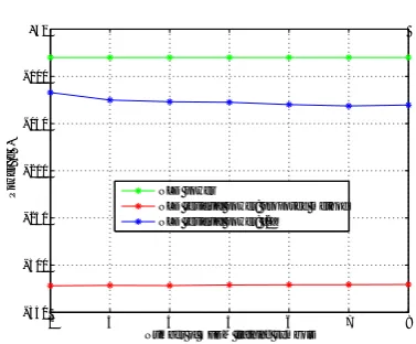
Figure (5) shows tha t our method leads to mitig ate almost all the self interf erence, so tha t the pow er of
ˆ
Y(m) becomes very closed to the noise pow er. However, with the method of [2], the RSI pow er increases with the NLD pow er beca use the NLD pow er is a limiting factor of the channel estima tion which leads to a bad estima tion of the channel.
To show the impact of the NLD on the Spectrum Sensing, figur (6) shows the ROC in various situa tions under γx=−10 dB. The simula tions par ameters in this
figur are similar to those of figur (5), only the NLD pow er is set to 45 dB under the linear componen t according NI 5791 indica tions [18]. The method of [2] leads to a linear ROC, which means tha t no meaningful informa tion about the PU sta tus can be obtained. By referring to figur (5), the RSI pow er is of -82 dB for a NLD pow er of -45 dBc, which means tha t γd in this
case is about 20 dB. This high RSI pow er leads to a harmful loss of perf ormance (see figur (3)). From the other hand, our method makes the ROC in FD mode almost colinear with tha t of the ROC of HD mode, which means tha t all SI and receiv er impairmen ts is mitig ated.
Figure (7) shows the PDR for a targ etα= 0.1 and PdH = 0.9. The ratio δincreases with the SNR. At a low SNR of -10 dB, δbecomes closed to 1, so tha t a negligible
−90 −85 −80 −75 −70 −65 −60 −55 −50 −45 −40 −105
−100 −95 −90 −85 −80 −75
NLD power (dBc)
Noise +RSI power (dB)
Noise only (H0 in HD) Proposed method Method of [2]
Figure 5. The power ofYˆ(m)underH0 obtained after applying: (1) our proposed method, (2) the method of [2] is applied and (3) under HD mode
0 0.1 0.2 0.3 0.4 0.5 0.6 0.7 0.8 0.9 1
0 0.1 0.2 0.3 0.4 0.5 0.6 0.7 0.8 0.9 1
p fa pd
ED−HD
ED− FD with NLD suppression: proposed
ED− FD with NLD suppression [2]
Figure 6. The ROC curve after applying the proposed technique of NLD suppression
−20 −18 −16 −14 −12 −10 −8
0.4 0.5 0.6 0.7 0.8 0.9 1
γ
x(dB)
δ
Figure 7. The gain ratio:δ= P
F d
PdH for different values of SNR
perf ormance loss is happen. As the SNR decreases the detection process in FD mode becomes more sensitiv e to the RSI pow er.
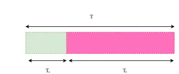
Figure 8. Activity period of SU under HD functioning is divide into Sensing sub-period (Ts) and Transmission sub-period (Tt).
5. Throughput Analysis
In this section, we anal yse the SU perf ormance by discussing from throughput viewpoin t. Although FD-CR is introd uced to enhance the SU data rate, the RSI affects both false alarm and detection probabilities as discussed in section (3). Consequen tly, the throughput of SU under FD can be lower than the throughput under HD for some circumstances.
First , let us presen t the activity period, T, of SU in HD mode (see figur (8)). We assume tha t this activity can be divided into sensing period (Ts) and transmitting
period (Tt). The throughput of SU (RSU) is affected
by the sensing perf ormance since the detection of the PU is not perf ect and it can be done up to a targ et pair (pf a, pd). After the sensing period, SU can continue
transmitting in one of the tw o following scenarios: 1. Missed Detection: SU decides tha t there is no
activ e PU in the bandwid th, while PU is trul y activ e. In this case, SU becomes activ e and interf eres with PU
2. Reject: SU rejects the hypothesis H1 by detecting correctl y the absence of PU. Theref ore SU becomes activ e
As SU is activ e under Missed Detection and Reject cases, RSUbecomes the sum of the tw o throughputs: R0under
Reject case and R1 under Missed Detection case.
RSU =R0+R1 (25)
Let us denote by p0 the probability tha t PU is trul y absen t, and p1 the probability tha t PU is trul y transmitting, with p0 +p1 = 1. Accordingl y, R1 and R0 are giv en by [21]:
R0 =τC0 1−pf a
!
p0 (26)
R1 =τC1 1−pd
!
p1 (27)
where τ= Tt
T is the ratio of the transmission period with
respect to the overall activity period, and C0 (resp. C1) is the throughput of SU when it oper ates under H0 (resp. (H1)). By assuming tha t SU and PU signals are sta tisticall y independen t, white and Gaussian, C0 and
C1 are giv en by:
C0 =log2(1 +γr) (28)
C1 =log2(1 +ζr) (29)
where γris the SNR and ζrand the Signal to Noise and
Interf erence Ratio (SNIR) of SU signal at the Secondary receiv er.
R1 represen ts the interf ering throughput of SU transmission to PU. This throughput shoul d be minimized as possible by increasing pd in order
to do not affect the PU transmission. In contrast, R0 represen ts the gainful throughput of SU to be maximized by decreasing pf a, since it resul ts from
a true decision on the absence of PU. On the other hand, both R0 and R1 are rela ted to τ. In FD-CR the ratio τ is equal to one since no silence period is required. Even though this fact is importan t for the SU throughput , it can affect the Spectrum Sensing reliability , by increasing pf a(i.e.decreasing the gainful
throughput R0) and decreasing pd (i.e. increasing the
interf erence throughput R1). To establish the minim um requiremen t of SU transmission in FD in order to exceed the throughput in HD; tw o conditions have to be respected:
1. the interf ering throughput under HD mode represen ts the upper bound of the interf ering throughput under FD mode. This means the interf erence amoun t under FD mode must not exceed tha t under HD mode.
2. The gainful throughput under HD mode repre-sents the lower bound of the FD gainful through-put.
The firs condition can be expressed as follows:
C1(1−pf
d)p1 ≤τC1(1−phd)p1 (30)
The left -hand side of the equa tion (30) represen ts the interf ering throughput in FD mode, whereas the right -hand side represen ts the interf ering throughput under HD mode. Accordingl y,pdf becomes:
pfd ≥1−τ(1−ph
d) (31)
Equa tion (31) shows tha t pfd is a function of phd and τ. The condition presen ted in equa tion (31) represen ts the limit detection rate to be reached (pf
d = 1−τ(1−phd)) in
order to respect the same interf ering throughput of SU to PU transmission for giv en phdand τ.
0.8 0.82 0.84 0.86 0.88 0.9 0.92 0.94 0.96 0.98 1
p
d h
0.82 0.84 0.86 0.88 0.9 0.92 0.94 0.96 0.98 1
pd
f
τ = 0.5
τ = 0.75
τ = 0.9
τ = 0.99
Figure 9. Variation ofpfd in terms of phd for various values ofτ
throughput increases rela tiv ely to HD mode. Increasing the detection rate in FD comparing to HD leads to compensa te the additional interf erence caused by the elimina tion of the silence period. Forτ = 0.5 and 0.75, pfd shoul d be grea ter than 0.95 and 0.93 respectiv ely for phd = 0.9. For τ = 0.99 (SU practicall y functions in FD mode ),pfd and phd becomes approxima tel y of the same values.
Reg arding the gainful throughput (2nd condition), R0, the condition resul ting in increasing the SU throughput in FD mode rela tiv ely to HD can be introd uced by:
C1(1−pf
f a)p1 ≥τC1(1−p h
f a)p1 (32)
This equa tion resul ts in the upper bound of the false alarm rate of SU to be respected in order to increase the gainful throughput of FD rela tiv ely to HD:
pf af ≤1−τ(1−ph
f a) (33)
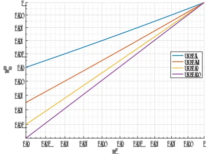
Figure (10) shows the upper bound of pf af , bell ow which the FD gainful throughput exceeds the one of HD mode. pf ah and pff a are linear ly correla ted. On the other hand, it is clear from this figur tha t the upper bound of pff agrows inversel y to τ. Increasing pf adoes
not affect the PU transmission, but it prev ents SU from using efficien tly the spectrum opportunity .
In figur (11), we examine the gainful throughput (R0) of SU in terms of SNR for various values of pf a. Note tha t pf ah is fixe at 0.1, τ= 0.75 and p0 =
0.9. As shown in this figure the throughput decreases with the increase of pf a, this is due to the spectrum
opportunity loss. On the other hand, forpf af = 0.4, the FD throughput becomes lower than the HD one. This means the functioning in HD mode becomes much interesting to SU.
0.05 0.1 0.15 0.2 0.25
p fa h 0
0.1 0.2 0.3 0.4 0.5 0.6 0.7
pfa
f
τ = 0.5
τ = 0.75
τ = 0.9
τ = 0.99
Figure 10. Variation ofpf af in terms ofphf afor various values of
τ
-10 -8 -6 -4 -2 0 2 4 6 8 10
SNR (dB)
0 0.5 1 1.5 2 2.5 3
Thoughputs (bits/sec/Hz)
R
0 (HD)
FD: pfaf=0.1 FD: p
fa f=0.2
FD: p
fa f=0.4
Figure 11. Evolution of the throughput of SU in terms of SNR (dB) for HD and FD mode
6. Conclusion
In this paper , the Spectrum Sensing and the Through-put of Full-Duplex Cognitiv e Radio are discussed. Reg arding the Spectrum Sensing, a rela tion betw een the detection and false alarm probabilities under Full-Duplex and Half -Full-Duplex modes is deriv ed. Such a rela-tion shows the effect of the Resid ual Self -Interf erence on the Spectrum Sensing perf ormance. In order to red uce the RSI pow er, the Non-Linear Distortion (NLD) of the Low Noise Amplifie is addressed by proposing a new algorithm to suppress it. The proposed algorithm shows its efficiency by red ucing the RSI pow er and leading to enhance the Spectrum Sensing perf ormance. In addi-tion, the Secondary User Throughput in Full-Duplex mode is anal ysed by deriving the upper bound of the false alarm rate and the lower bound of the detection rate. When these tw o bounds are not respected, the throughput of SU under Half -Duplex mode becomes higher than the one under Full-Duplex, which means no benefi is gained from the Full-Duplex functioning.
8 EAI Endorsed Transactions
on
Cognitive Communications
Appendix A. Appendix
A.1.
i.i.d.
property in Frequency Domain
Let r(n) be ani.i.d.time-domain signal. The DFT,R(m), of the r(n) is define as follows:
R(m) =
L
X
n=1
r(n)e−j2πmn
L (A.1)
Where L is the number of sam ples of r(n). According to the Central Limit Theorem (CLT), R(m) follows asym ptoticall y a Gaussian distribution for a larg e L. Based on [22], tw o normal variables are independen t if and only if (if f) they are uncorrela ted.
The correla tion, C(m1, m2), of R(m1) and R(m2)∀m1 ,
m2 is giv en as follows:
C(m1, m2) =E[R(m1)R∗(m2)
=E L X
n1,n2=1
r(n1)r∗(n2)e−j2π
n1m1−m2n2
L = L X
n1=n2=1
E
|r(n1)|2
e
−j2π(m1−m2 )n1
L
+
L
X
n1,n2=1
E r(n1)r
∗
(n2)
| {z }
=0, since r(n)is i.i.d.
e−j2π(n1m1
−n2m2 )
L
=Eh|r(n1)|2i
L
X
n1=1
e−j2π(m1−m2)n1
L
| {z }
=0
= 0 (A.2)
As C(m1, m2) = 0; ∀ m1 ,m2, theref ore R(m1) and
R(m2) become uncorrela ted and independen t since they are Gaussian.
A.2. Probability of Detection and Probability of
False Alarm
As by our assum ption ξ(m), W(m) and X(m), are asym ptoticall y Gaussian i.i.d., then ˆY(m) is also Gaussian and i.i.d.Theref ore, the Test Statistic, TED, of
equa tion (10) follows a normal distribution according to CLT for a larg e N. Under H0 (i.e. X(m) does not exist), the mean, µ0, and the variance, V0 ofTED can be
obtained as follows:
µ0 =E[T] =E
1 N N X m=1
|ξ(m) +W(m)|2
=σ 2
w+σd2 (A.3)
V0 =E[T2]−E2[T] = 1
N2E
N X m=1
|Yˆ(m)|2
2
−(σw2+σ2
d)2
= 1 N2E
N X
m1=m2=1
|Yˆ(m1)|4
+ 1 N2E
N X
m1,m2=1
|Yˆ(m1)|2Yˆ(m2)|2
−(σw2 +σ2
d)2
= 1 N2
N
X
m1=m2=1
E
|Yˆ(m1)|4
− 1 N(σ 2
w+σd2)2 (A.4)
Since ˆY(m) is Gaussian, then its kurtosis kurt( ˆY(m)) is zero.
kurt( ˆY(m)) =E[|Yˆ(m)|4]−E[ ˆY2(m)]−2E2[|Yˆ(m)|2] = 0
(A.5) Assuming tha t the real and the imaginary parts of ˆY(m) are independen t and of the same variance then E[ ˆY2(m)] becomes zero. Theref ore: E[|Yˆ(m)|4] =
2E2[|Yˆ(m)|]2 = 2(σw2 +σ2
d)2. Back to equa tion (A.4), the
variance, V0 becomes:
V0 = 1 N(σ
2
w+σd2)2 (A.6)
By following the same proced ure, µ1 and V1 can be obtained as follows under H1(X(m) exists):
µ1 =σw2+σd2+σx2 (A.7) V1 = N1 (σw2 +σd2+σx2)2 (A.8)
References
[1] A. Nasser , A. Mansour , K. C. Yao, H. Char ara, and M. Chaitou, “Spectrum sensing for full-duplex cognitiv e radio systems,” 11th International Conference on Cognitive Radio Oriented Wireless Networks (CROWNCOM), Grenobel, May 2016.
[2] Elsa yed Ahmed and Ahmed M. Eltawil, “All-digital self -interf erence cancella tion technique for full-d uplex systems,” IEEE Transaction on Wireless Communications,
vol. 14, no. 7, pp. 291–294, July 2015.
[3] E. Everett , A. Sahai, and A. Sabharw al, “Passiv e self -interf erence suppression for full-d uplex infr astructure nodes,” IEEE Transactions on Wireless Communication,
vol. 13, no. 2, pp. 680 – 694, Fevruary 2014.
[4] T. Yucek and H. Arslan, “A surv ey of spectrum sensing algorithms for cognitiv e radio applica tions,” IEEE Communication Surveys&Tutorials, vol. 11, no. 1, pp. 116
– 130, First Quarter 2009.
[5] A. Nasser , A. Mansour , K. C. Yao, and H. Abdallah,
[6] A. Nasser , A. Mansour , K.-C. Yao, Mohamad Chaitou, and H. Char ara, “Spa tial and time div ersities for canonical correla tion significanc test in spectrum sensing,” in 24th European Signal Processing Conference (EUSIPCO), August 2016, pp. 1232–1236.
[7] E. Ahmed, A. M. Eltawil, and A. Sabharw al, “Ra te gain region and design tradeoffs for full-d uplex wireless comm unica tions,” IEEE Transaction on Wireless Communications, vol. 12, no. 7, pp. 3556–3565, July 2013.
[8] A. Sahai, G. Patel, C. Dick, , and A. Sabharw al, “On the impact of phase noise on activ e cancela tion in wireless full-d uplex,” IEEE Transaction on Vehicular Technology,
vol. 62, no. 9, pp. 3494–4510, November 2013.
[9] D. W. Bliss, T. M. Hancock, and P. Schniter , “Hardw are phenomenol ogical effects on cochannel full-d uplex mimo rela y perf ormance,” in Asilomar Conference on Signals, Systems and Computers, 2012, pp. 34 – 39.
[10] E. Ahmed, A. M. Eltawil, and A. Sabharw al, “Self -interf erence cancella tion with nonlinear distortion sup-pression for full-d uplex systems,” Proceeding Asil omar Conference on Signals, Systems and Compututer , 2013, vol. II, p. 1199 âĂŞ1203.
[11] W. Afi and M. Krunz, “Adaptiv e transmission-reception-sensing strategy for cognitiv e radios with full-duplex capabilities,” in International Symposium on Dynamic Spectrum Access Networks (DYSPAN), 2014, pp.
149 – 160.
[12] J. Heo, H. Ju, Sungsoo Park, E. Kim, and D. Hong, “Sim ultaneous sensing and transmission in cognitiv e radio,” IEEE Transaction on Wireless Communications, vol.
13, no. 4, pp. 149 – 160, April 2014.
[13] T. Riihonen and R. Wichman, “Energy detection in fulld uplex cognitiv e radios under resid ual self -interf erence,” 9th International Conference on Cognitive Radio Oriented Wireless Networks (CROWNCOM), pp. 57
– 60, July 2014.
[14] W. Cheng, X. Zhang, and Hailin Zhang, “Full-d uplex spectrum-sensing and mac-protocol for multichannel nontime-sl otted cognitiv e radio netw orks,” IEEE Journal on Selected Areas in Communications, vol. 33, no. 5, pp.
820 – 831, May 2015.
[15] W. Afi and M. Krunz, “Incorpor ating self -interf erence suppression for full-d uplex oper ation in opportunistic spectrum access systems,” IEEE Transaction on Wireless Communications, vol. 14, no. 4, pp. 2180 – 2191, April
2015.
[16] W. Cheng, X. Zhang, , and H. Zhang, “Full duplex spectrum sensing in non-time-sl otted cognitiv e radio netw orks,” in The IEEE Military Communications Conference (Milcom), 2011, pp. 1029 – 1034.
[17] T. Schenk, “Rf imperf ections in high-r ate wireless systems, impact and digital compensa tion,” New York, NY, USA: Spring er-Verlag 2008.
[18] NI 5644R, “User man ual and specific tions,”
Nat. Instrum., Austin, TX, USA, Available:
http://www .ni.com/da tasheet/pdf/en/ds-422.
[19] Behzad Raza vi, Design of Analog CMOS Integrated Circuits, McGraw-Hill, Inc., New York, NY, USA, 1
edition, 2001.
[20] Y. Kang, K. Kim, and H. Park, “Efficien t DFT-based channel estima tion for ofdm systems on multipa th channels,” IET Communication, vol. 1, no. 2, pp. 197–
202, April 2007.
[21] Y. C. Liang, Y. Zeng, E. C. Y. Peh, and A. T. Hoang, “Sensing- throughput tradeoff for cognitiv e radio netw orks,” IEEE Transactions on Wireless Communications, vol. 7, no. 4, pp. 1326–1337, April
2008.
[22] M. Barkat,Signal Detection and Estimation, Artech House
radar libr ary. Artech House, 2005.
10 EAI Endorsed Transactions
on
Cognitive Communications

![Figure 5. The power of Yˆ(m) under H0 obtained after applying:(1) our proposed method, (2) the method of [2] is applied and (3)under HD mode](https://thumb-us.123doks.com/thumbv2/123dok_us/8410054.1690522/6.595.335.519.308.452/figure-power-obtained-applying-proposed-method-method-applied.webp)