© 2015 IJSRSET | Volume 1 | Issue 6 | Print ISSN : 2395-1990 | Online ISSN : 2394-4099 Themed Section: Engineering and Technology
Reducing Harmonics Using Current Source Topology for Wind
Turbines
Aarthi G P
Electrical and Electronics Engineering, Kongu Polytechnic College, Thoppupalayam, Perundurai, Erode, Tamil Nadu, India
ABSTRACT
In this study, a Current-Source Inverter (CSI) topology tailored for large multi-megawatt wind turbine applications. The cable distance between the generator and the mains enables the realization of a significant portion of the DClink inductance. In order to improve the efficiency and to allow the possible utilization of rugged inexpensive Thyristors, PWM modulation is not used in the main conversion chain. The 5th and 7th harmonics of the mains line currents are reduced by choosing a proper nominal operating point for the turbine. Further harmonic reduction is achieved through an active filter. Simulation results of the dynamic model of the wind system are presented, for different operating points, to show the good performance of the system.
Keywords: Current-Source Topology, Harmonics Reduction, Wind Turbines
I.
INTRODUCTION
Large multi-megawatt wind turbines will be more and more pervasive in the next future bringing stringent requirements to their energy conversion processes as well as on their operational costs. Reduced construction and lifecycle costs, low harmonic content in the line currents delivered to the mains, high-efficiency and reliability are all factors of prominent importance for such systems.
The paper proposes a topological solution suitable to satisfy these requirements and based on a Current-Source Inverter (CSI) concept. The nature of the CSI topologies takes advantage of the inductance contribution present in the loop constituting the DC-link. As consequence this solution exploits the distance between the generator and the mains characterizing the wind turbines to realize a significant portion of the DC-link inductance.
In order to improve the efficiency and to allow the utilization of rugged inexpensive semiconductors (Thyristors), the proposed solution avoids PWM
modulation in the “Main Conversion Chain” (MCC). This solution adopts reduced cost topological sub-systems devoted to convert the total average power caught from the wind.
Authors (chen and spooner,2003) have proposed a CSI topology based on a single phase-angle controlled thyristor bridge but such a solution requires compensation. As consequence the active compensator needs to be designed for significant current ratings and, in case of its failure, no possible alternative would exist to compensate the reactive power.
Conversely, the topological solution proposed here relies on two CSI bridges connected in series. Both are still controlled via the well-established phase-angle control technique but using exactly opposite control angles. It choices the reduction in the 5th and 7th harmonic of the mains line currents at the nominal operating point of the turbine simply using the MCC only.
frequency. Failure of the filter does not prevent a-priori the system from operating at full power, since this feature is intrinsic in the MCC itself. The control methodology used for the active filter relies on a newly proposed technique whose basis has been introduced by the authors in (tenca and lipo, 2004).
The controller relies on the real-time minimization of a proper time-varying functional, whose analytical limit for t → +∞ equals the average power of the current error as defined in traditional signal theory. The methodology realizes true feedback in the current synthesis process, without any need to rely on off-line, open-loop, computations or on a-priori assumed waveforms.
II.
METHODS AND MATERIAL
A. Overview of the Problem
The converters present in the several existing wind turbines are usually based on classical Voltage Source Inverter (VSI) topologies and radial-flux generators. In many state-of-the-art wind turbines the generator and the needed VSI converters are located in the nacelle at the top of the tower leaving only the Mains interconnection transformer at the ground level.
A non-negligible reason for this arrangement lies in the need to minimize these stray inductances that would be otherwise harmful to the proper operation of the VSI type conversion chain. Such an arrangement renders the wind turbine expensive and difficult to maintain because several bulky and reliability-critical components (especially the DClink capacitors) are required.
Furthermore in order to meet the power quality standards (such as IEEE 519-1992) significant PWM modulation, is used in the main conversion chain which is often rated for the totality of the generated power.
This reduces the efficiency, mainly because of the switching losses, and enhances the stresses on the main switches ultimately increasing their likelihood of failure and the system life cycle-costs. The rapidly growing power ratings of the wind turbines simply aggravate these drawbacks.
B. Proposed Topological Solution
The authors propose in this paper an alternative current source topology shown in Figure 1 where the square boxes identify topological structures organized as the common three-phase bridges. The topology is based on a current source concept whose intrinsic nature takes advantage of the distance between the generator and the mains and this feature is exploited indeed to realize a major portion of the needed DC-link inductance.
Only two power cables are needed between the nacelle and ground and only a very reliable switch module (diode bridge A) is located at the top of the tower thereby reducing the weight of the nacelle and the overall maintenance costs.
The total average power is converted by the two series connected current-source inverters (B and C) independently supplied by the two equal secondary‟s of a Y-Y-Delta transformer. They are part of the Main Conversion Chain (MCC) (drawn with gray background in Figure 1) and are controlled by the well-known phase-control technique, whose switching frequency equals the mains frequency (no PWM) thereby minimizing the switching losses.
This reduces significantly the cost of the topology, renders it suitable for very high power wind turbines and improves its reliability due to the well-known ruggedness characterizing the use of thyristors.
C. Design of the Main Conversion Chain
This section describes the peculiar design choices concerning the MCC leading to an improved spectrum of the mains line currents. In the following K_thyr and K_fc are defined as the ratios between the phase secondary voltage and primary line-toline voltage for the secondaries connected to the thyristorsn and fully controllable inverter respectively.
The phasecontrol angleϕ∈ [0 , π)[ rad ] is defined for the thyristor inverter according to the commonly used conventions. Idc represents the DC-link current assumed ideally constant and n∈Z is the harmonic order of the n-th spectral component in n-the bilateral Fourier spectrum.
It can be proven straight forwardly that the complex Fourier coefficient C_Im(n) associated with the n-th spectral component of the phase a mains line current has the form shown in Equation (1).
( ) (
) ( ) ( )
where n Z -{0} and:
A(n)=
( π) ( π) [ ( ) ]( )
(
)
=
[
( )
( )
]
Figure 2 shows the ratios 2 ּ | C_Im(n) | / Idc computed from Equation (1) for n = {5,7}, equal transformer secondaries characterized by K_thyr = K_fc = 1/sqrt(3) and φ in the interval [π/2, π) where both bridges operate as inverters.
The analysis of Equation (1) reveals that the three values of the control angle φ listed in Table I already reduce the harmonic content of the mains line current without need for PWM action. In particular the angle φ3 reduces the total average power contained in the 5th and 7th harmonic and allows a good utilization factor of the two bridges.
It should be observed that the pitch control of the propeller blades usually keeps the generator at its nominal rotational speed in a suitable range of wind speeds.
This suggests that one must design the generator with as low stray inductance and resistance as possible. In this manner the output voltage undergoes reduced dependence from the output current and it is maintained close to its nominal value by the indirect action of the pitch controller. A specially designed axial-flux permanent magnet generator has been chosen as suitable solution capable to satisfy such a requirement.
TABLE I
VALUES OF THE PHASE- CONTROL ANGLE φ REDUCING THE HARMONIC CONTENT OF THE
MAINS LINE CURRENT
ϕ1 = (9 /10) π Nullifies the 5th harmonic
ϕ 2 = (13 / 14) π Nullifies the 7th harmonic
ϕ3 = 0.914 π Minimizes the total average power in the 5th and 7th harmonics
The additional key design choice concerning the generator is the value of its nominal voltage. This value is chosen in such a way that the DC-link controller is forced to issue the values ±φ3 of the control angles to the bridges B and C at nominal mains voltage. In this manner the 5th and 7th harmonics in the line currents are intrinsically reduced as explained previously. In general any specific component of the MCC must be designed for the nominal operating point characterized by the values of the electrical quantities associated with the control angle φ3.
The DC-link current is regulated by means of variations of the phase-control angle φ. In the steady state such variations are small and occur around the nominal value φ3. The DC-link current controller can be implemented very simply and cost-effectively by using a suitable PI regulator whose input is the error between the desired and actual DClink current. Additionally, several PI regulators are available off-the shelf in the market helping to reduce the design costs.
Nevertheless the possible use of a sensor measuring the voltage directly at the output of the diode bridge (A), might certainly improve the dynamic of the DC-link current, provided that a more complex controller is used.
The proposed topology has been fully modeled in Simulink also with the goal to define the design of a 10 kW prototype currently under construction. The following figures show some of the design simulations results aimed at illustrating the behavior of the converter. The most important parameters concerning the MCC are: Ldc = 100 mH, mains line-to-line voltage = 460 V, transformer secondary line-to-line voltage = 460 V, nominal
Idc = 10 A and peak voltage of the generator phase backemf = 644 V.
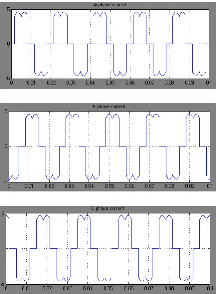
Figure 3 shows that the regulator at steady state maintains φ in the neighborhood of φ3 (~ 165 degrees) when the properly designed generator operates at its nominal point. Figure 4, in the interval [0.22 , 0.25] [s], shows the line currents (blue) when φ and Idc are close to φ3 and 12.5 A respectively.
The undesired harmonics are further reduced through an active harmonic compensator constituted by a VSI connected to the same secondary of the bridge C via series inductances of proper value. This VSI (drawn in green in Figure 1) is not part of the MCC and it does not deliver any active or reactive power at mains frequency.
The active harmonic compensator uses fully controllable switches operating at frequency much higher than the mains frequency. These switches normally undergo higher dynamic stresses than those used in the MCC and belong to a type (usually an IGBT) less reliable than the Thyristor.
Hence the active harmonic compensator is the sub-system most prone to fail. However, the proposed solution avoids the possible complete loss which might impair the main functionality of the wind turbine. If the active harmonic compensator fails, it can be completely disconnected from the MCC leaving it capable of operating at full power, with unity fundamental power factor and with reduced 5th and 7th mains line current harmonics. Obviously in this emergency case the spectrum of the mains line current is degraded.
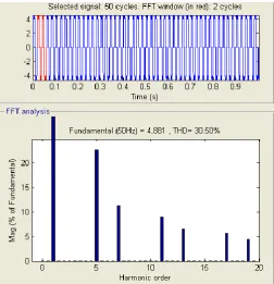
Mains current before compensation
Figure 2: Mains line current before active harmonic compensation
III.
RESULTS AND DISCUSSION
Principles of the Variational Controller
The control technique used for the active harmonic compensator belongs to the normal PWM class of controllers but the switching instants and sequence of switching states for the VSI are determined by a carrierless approach based on the real-time minimization of the time varying real functional Ψ(t) defined in ℜ+ and shown in Equation (2).
Ψ (t) is constituted by the sum of 3 positive definite functions of time Ψγ(t), one for each mains phase. The three mains phases are identified by the letters {a,b,c} represented symbolically by the subscript variable γ. The functions iγ(t) and iγ_ref(t) constitute the actual and reference line currents of the active harmonic compensator respectively.
( ) ∑ ∫ [ ( ) ( )]2
d (2)
={a,b,c}
Under the hypothesis that each line current is a bounded and alternating signal with period T, it can be observed straightforwardly that the limit of Ψγ(t) , γ={a,b,c} for t → +∞ is finite and equal to the definite integral written at the right-hand side (RHS) of Equation (3).
∫ [ ( ) ( )] = (3)
= ∫ [ ( ) ( )]2 d
Such definite integral constitutes the average power of the periodic “error” signal iγ(t) - iγ_ref(t) as defined by the signal theory and it can be expressed in the frequency domain via the Parseval‟s identity. Therefore Equation (3) can be rewritten as Equation (4), where αIγ(n) and αIγ_ref(n) are the n-th bilateral Fourier spectral components of iγ(t) and iγ_ref(t) respectively.
( ) ∑ | ( ) ( )|
(4) Where = {a,b,c}
The RHS of Equation (4) can be interpreted also as the squared “distance” in the sense of the Euclidean norm- between the two infinite dimensional vectors whose elements are αIγ(n) and αIγ_ref(n). The synthesis of the line currents iγ(t) capable of minimizing the average power expressed by the RHS of Equation (3) can be seen as a problem of calculus of variations with moving boundaries .
The controller builds in real-time the sequence of switching states generating the currents iγ(t) capable to make Ψ(t) converge towards its absolute minimum (i.e. 0). Consequently, because of Equation (3), the controller minimizes asymptotically the functional comprised of the average power, thus solving in real-time the aforementioned variational problem.
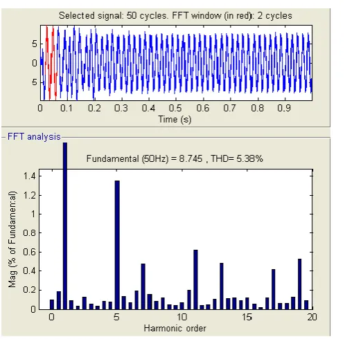
Such a vision of the line currents synthesis justifies the name “variational controller” assigned to this technique. Furthermore it can be proven easily that when the reference signals iγ_ref(t) are sinusoidal, this control technique minimizes the Total Harmonic Distorsion (THD) factor of the synthesized line currents iγ(t).
Figure 5 : Total Harmonic Distortion present in the system after active harmonic compensator
IV.
CONCLUSION
A cost-effective and rugged conversion topology conceived for the emerging high-power wind turbines has been presented. The proposed topology is based on a CSI concept that exploits the intrinsic distance between the generator and the mains peculiar of the wind turbines. The proposed solution does not use PWM modulation in the conversion of the average power allowing the use of inexpensive and rugged Thyristors. At the same time, it guarantees unitary fundamental power factor and somehow reduced harmonic content already without filtering action. Further harmonic reduction is provided by an active harmonic compensator whose possible failure does not impede the full power operation of the turbine. The active harmonic compensator is controlled via a newly proposed carrierless variational method capable of real-time, true feedback, operation.
V.
REFERENCES
[1] Z. Chen, E. Spooner, “Current source thyristor inverter and its active compensation system”, IEE Proceedings Generation Transmission and Distribution. Vol. 150 No. 4 July 2003.
[2] A.M. El-Tamaly, H.H. El-Tamaly, E. Cengelci, P.N. Enjeti, E. Muljadi: “Low cost PWM converter for utility interface of variable speed wind turbine generators”, Applied Power
Electronics Conference and Exposition, 1999. APEC '99. Fourteenth Annual, Volume 2, 14-18 March 1999, Page(s): 889 –895.
[3] R. Pena, J.C. Clare, G.M. Asher: “A doubly fed induction generator using back-to-back PWM converters supplying an isolated load from a variable speed wind turbine”, Electric Power Applications, IEE Proceedings, Volume: 143 Issue: 5, Sept. 1996, Page(s): 380 –387.
[4] G. Poddar, A. Joseph, A.K. Unnikrishnan: “Sensorless variable-speed controller for existing fixed-speed wind power generator with unity power- factor operation”, IEEE Transactions on Industrial Electronics, Volume: 50 Issue: 5, Oct. 2003, Page(s): 1007 –1015.
[5] C.L. Kana, M. Thamodharan, A. Wolf: “System management of a wind-energy converter”, IEEE Transactions on Power Electronics, Volume: 16 Issue: 3, May 2001, Page(s): 375 –381.
[6] E. Muljadi, C.P. Butterfield: “Pitch-controlled variable-speed wind turbine generation”, IEEE Transactions on Industry Applications, Volume: 37 Issue: 1, Jan.-Feb. 2001, Page(s): 240 –246. [7] P. Tenca, T.A. Lipo: “Synthesis of Desired AC
Line Currents in Current-sourced DC-AC Converters”, IEE Power Electronics Machines and Drives 2004, PEMD „04, Volume 2, Page(s): 656-661, Edinburgh, 31 March – 2 April 2004.
[8] P. Wood: Switching Power Converters. (book) Van Nostrand Reinhold Company, 1981.
[9] B.R. Pelly: Thyristor Phase-Controlled Converters and Cycloconverters. (book) Wiley-Interscience, 1971.
[10] A. Papoulis: The Fourier Integral and its Applications. (book) Mc Graw-Hill Book Company, 1962.
[11] S.I. Baskakov: Signals and Circuits. (book) MIR publisher Moscow, 1986.
[12] A. Papoulis: Signal Analysis. (book) Mc Graw-Hill Book Company, 1984.
[13] H. S. Black: Modulation Theory. (book) D. Van Nostrand Company Inc. , 1953.
[14] H. Sagan: Introduction to the Calculus of Variations. (book) Dover Publications Inc. New York, 1969.