Annotation of the Medical Images Using Quick Response
Codes
Gir¯uta Kazakeviˇci¯ut˙e–Januškeviˇcien˙e1, Andrius Ušinskas2, Eugenijus Januškeviˇcius3,
Jurgita Ušinskien˙e4, and Simona Letautien˙e5
1
Dept. of Graphical systems, Vilnius Gediminas Technical University Saul˙etekio av. 11, Vilnius, Lithuania
Dept. of Electronic Systems, Vilnius Gediminas Technical University Naugarduko str. 41, Vilnius, Lithuania
Laboratory of Computer Aided Architectural Design, Vilnius Gediminas Technical University Pylimo str. 26/1, Vilnius, Lithuania
Institute of Oncology, Vilnius University Santariškiu˛ str., Vilnius, Lithuania
Institute of Oncology, Vilnius University Santariškiu˛ str., Vilnius, Lithuania
Abstract. The article proposes a novel annotating method of sufficient capacity and intended not only on-line but for off-line using for information preservation all advantages of two-dimensional barcodes. The semantic annotations are embedded directly into the reasonably chosen area of the image and bound by spatial identifiers with corresponding regions. The embedding method deals with the different quality requirements of the regions. Two-dimensional QR codes are used as the physical carrier of the annotation, providing the industrial grade for information detection, resilience and error correction capabilities. The annotation is distributed in a series of QR codes for efficient use of the available space. The results reveal that the spa-tial domain based technique is faster and has higher data embedding capacity than JPEG 2000 based. The amount of embedded information preserving the acceptable image quality in both proposed embedding cases is higher the average length of the presented original descriptions.
Keywords:annotation, wavelet, JPEG 2000, DICOM, IW-SSIM.
1.
Introduction
creation a computer-based assistant, collecting information about the medical inspection process, same as to query and retrieve image from medical record databases. Automated or semi-automated content-based image retrieval (CBIR) systems based on low-level fea-tures have demonstrated poor performance when applied to databases with a broad spec-trum of imaging modalities, anatomies, and pathologies [15]. The search by particular textual description, or by fusing the results of visual and textual techniques, is more pre-cise compared to the search by the image content. Such method provides better means to organize and search an image database [14].
In this paper, we propose spatial and wavelet-based annotating algorithms for medi-cal image regions embedding semantic descriptions directly into the spatially disjointed, insignificant regions of the image, associating them with the region of interest. 2D Quick Response (QR) codes are used as the carriers of structurized information. Use of standard QR codes allows relying on the existing proven solutions in the fields of error correction, reliable information encoding, and automatic spatial identification. Comparative analysis of capacity in spatial and wavelet domains is presented considering the optimal embed-ding and size of QR codes. Typical usage scenarios are targeted to the off-line usage of medical data and include research work, lectures, conference talks, clinical meetings, and similar designations when access to the medical information databases is impossible or unacceptable. The annotation method is not a permanent replacement of database records; it is targeted as a tool for pointing out peculiarities of the image. The embedded annota-tions, encapsulating essential knowledge about the content of medical images, could be used as training data in the machine learning approaches that are employed in the auto-matic annotation of images [6].
The novel aspects of our work:
– we use QR codes as the information carrier, exploiting their positive features, like
industry-proven detection methods, error resilience, and correction;
– instead of using single QR block, we split the annotation into separate substrings,
making the embedding of smaller QR block spatially efficient in both spatial and wavelet domains;
– the recovered substrings are automatically reassembled at the decoding stage,
allow-ing a number of annotations to be placed in the sallow-ingle image;
– the spatial position of the region of interest is included in the structure of an
annota-tion, thus allowing arbitrary placement of every QR block.
The related annotating methods for medical images and their drawbacks are presented in Section 2. The secure compression and quality evaluation methods of annotated med-ical images are also discussed in this section. The proposed method for semantic anno-tation embedding in the spatial and wavelet domains of medical images is presented in Section 3. The testing conditions, experimental results, and discussions are presented in Section 4. The article is completed with concluding remarks in Section 5.
2.
Related Works
depends on the objectives of the application area, image type, file format and requirements for annotations.
Related annotation methods of medical imagery and their peculiarities are presented in the following subsection. We also discuss the secure level of compression for medical images and the modern methods of quality evaluation for annotated medical images of various modalities, too, in the subsequent subsection.
2.1. Annotation of the Medical Images Based on Information Embedding Methods
Data embedding, else called data hiding, is a useful technique for many applications. However, only a few applications use these methods for the semantic annotation of the medical images.
In [21] authors present a technique for hiding the high volume of the textual patient information in the medical images at the bit level along with security. Local Ternary Pat-tern technique is used to embed the patient information into medical images for efficient storage. Local Binary Pattern technique is mainly used for security reason of the patient information.
Authors of [12] hide medical message into the Discrete Cosine Transform (DCT) co-efficients of the image 8-by-8 square blocks. Authors of [1] utilize Pixel Value Differenc-ing for contrast regions identification in the image and a HammDifferenc-ing code for embeddDifferenc-ing confidential patient information into the region of non-interest (RONI) of the cover image. In [12], [1] are used information embedding methods for steganography and emphasized confidentiality and security of the medical data. Comparing with annotative their require-ments differ [17]. The medical semantic information should be obtainable in annotated medical images for knowledge sharing.
In [8] authors emphasize the usage of the fragile block based watermarking to verify the integrity of the medical image content. For this purpose, they segment the image into the region of interest (ROI), RONI and the border region. Further, divide ROI and RONI into non-overlapping blocks and map each ROI block to a block in RONI. Information of ROI and authentication data are embedded in border pixels.
In [5] the focus is on the complementary role of watermarking concerning medical information security and management. The authors conclude that the distortionless and robust watermarking for the medical imaging may be reached using reversible water-marking methods. The reversible data hiding algorithms are not relevant to the annotative purpose as objectives of watermarking and media description are different [17].
In [10] a high fidelity image watermarking for annotation with robustness to mod-erate distortion is proposed. The high fidelity of the embedded annotations is achieved introducing a pixel domain visual model (an entropy and a differential standard deviation filters) to estimate visual sensitivity to noise. Based on that model, authors embedded two kinds of watermarks in the Lapped Biorthogonal Transform domain: a pilot watermark, indicating the existence of the watermark and the information watermark. High fidelity is a demanding requirement for annotating medical images using information embedding methods.
In the article [19] have been presented the spatial domain technique for the medical image that embeds the watermark around the ROI in a spiral way. The watermark (ROI image) is the values of bitplanes of wavelet coefficients in low-pass filtered approximation
In [20], [9], [16] robust wavelet-based image multi-watermarking algorithms are ap-plied, capable of imperceptibly embedding all needed information to manage the medical images. The multiple watermarks are devoted to image authentication, retrieval, medical data protection and archiving. In [20] “annotation watermark” (the patient’s personal data, diagnosis, and health history) is embedded into the lowest Discrete Wavelet Transform
(DWT) level subbands – into the coefficient matrixHL1 (High-Low),LH1 (Low-High)
orHH1 (High-High) with the maximum energy. HereHL1,LH1 andHH1 subbands
denote the vertical, horizontal and diagonal features of the original image in the 1st DWT decomposition level. In [9] the “caption watermark” (the patient’s personal data, health
history, diagnostic reports, etc.) is embedded inHL2 subband coefficient matrix
(“High-Low” subimage of the 2nd DWT decomposition level). In [16] the double watermark (Electrocardiograph and Patients demographic text ID) is embedded in selected texture regions using two-level Haar wavelet decomposition.
In above presented articles about information embedding methods have not been used QR codes. Regardless of the 1D bitstream of data that is mostly used for embedding only in [21] is achieved high capacity. In all these methods the annotation information is avail-able at the image level. The keywords are associated with images instead of individual regions as in the presented method. The data are also embedded not only into the RONI of medical images but into ROI too [21], [10], [12], [20], [9], [16].
2D barcodes are also used in watermarking and steganography [13], [18], [4], [3], [11] usually as the obscured secure carrier of the embedded information.
In [13] is presented the watermarking in wavelet domain with several copies of 2D bar-codes inserted into the low-frequency components of the image. Authors of [18] propose robust image watermarking algorithm for JPEG images based on DWT-DFRNT multiple transform method. Discrete Fractional Random Transform (DFRNT) is performed on the two-level DWT subband coefficients and some copies of generated watermark through the 2D barcode are embedded into the subbands using quantization technique. Authors of [11] use two QR codes for medical data authentication that are embedded as 1D bitstreams
sep-arately into wavelet domainHL2 andHH2 subbands. In [4] and [3] authors present the
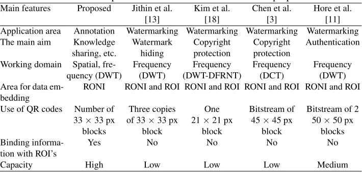
linearized 2D barcodes technique application for tamper detection, data concealing, and image copyright, respectively. The authors reduce QR code pattern from two-dimensions to bitstream for the convenient embedding into the low-frequency coefficients of the DCT. The methods that use QR codes as carriers of the embedded information were ana-lyzed and compared with proposed method (Table 1). In all anaana-lyzed methods, informa-tion about ROI’s is not linked with these regions. The data capacity is not high, rather medium and low. When authors use the higher version of QR codes, mostly they convert 2D codes into the 1D bitstream for convenient embedding, losing some advantages of QR codes converting them to bitstream. The area for data embedding is not RONI but low or high-frequency components of the image. As application area of the analyzed methods is watermarking, their primary objectives are copyright protection, authentication, and verification of content integrity.
Table 1.Main features comparison between state of the art and the proposed method
Main features Proposed Jithin et al. Kim et al. Chen et al. Hore et al.
[13] [18] [3] [11]
Application area Annotation Watermarking Watermarking Watermarking Watermarking The main aim Knowledge Watermark Copyright Copyright Authentication
sharing, etc. hiding protection protection
Working domain Spatial, fre- Frequency Frequency Frequency Frequency
quency (DWT) (DWT) (DWT-DFRNT) (DCT) (DWT)
Area for data em-bedding
RONI RONI and ROI RONI and ROI RONI and ROI RONI and ROI Use of QR codes Number of Three copies One Bitstream of Bitstream of 2 33×33 px of 33×33 px 21×21 px 45×45 px 50×50 px
blocks block block block blocks
Binding informa-tion with ROI’s
Yes No No No No
Capacity High Low Low Low Medium
description (annotation), image quality evaluation are the areas of information embedding. These areas have some similarities (an example, imperceptibility of embedded data into a host media, limitations due to the size of the embedded data), but their requirements differ [17], and the same algorithms are not expedient to use for all these areas.
2.2. Evaluation of Quality of the Annotated and Compressed Images
The users of medical imaging systems, typically physicians, focus on the pathological region in a medical image. The quality of other areas may be irrelevant for diagnostic ac-curacy. The characteristics of medical images differ from that of natural images, exposing huge volumes of tightly packed data in high dynamic ranges – from 8 up to 16 bits per single information channel.
The increased volume of medical data needs more and more storage space and more time for transmission. Compression of medical image data overcomes the problem of the data storage, time spent on the data transfer, bandwidth limitations, access speeds, costs, loss of the information and processing of the data. It is important to maximize compression while maintaining clinical relevance, i.e. the compression artifacts should not be visible in the images for diagnosis.
regions can be encoded with low quality, using lossy compression. JPEG 2000 has a fea-ture called ROI, and it suits for such applications [2].
We use the content annotation technique based on lossless compression and without compression, due to the usage and compression requirements for the medical images. In JPEG 2000 standard for lossless compression has used the biorthogonal 5/3 LeGall wavelet. The reversible integer (5,3) filter is much faster than the irreversible (9,7) one, as a result of integer arithmetic and smaller filter lengths.
For the medical image quality evaluation, it is expedient to use the automated objective quality assessment methods that are guided by the human vision model in order to reflect human perception accurately. Information content weighted structural similarity measure
(IW-SSIM) [28], based on the Structural Similarity Index (SSIM) [27] and its
multi-scale variant (M S-SSIM) [29] as the state of the art metrics were chosen. We evaluate
the quality and fitness of the image to the particular number/length of annotations using DICOM-based and lossless JPEG 2000-based algorithms.
An objective measurement of medical image quality is directly related to the diagnos-tic accuracy of the medical images. However, because of the differences in the charac-teristics of medical image contents, image formats, and users, existing objective natural
image quality metrics, such as mean squared error (M SE) and peak signal to noise ratio
(P SN R), are not directly related to human perception and does not provide satisfactory results [27], [26].
3.
Proposed Method for Semantic Annotation of the Medical Images
The requirements have been raised to the quality of medical images, especially for re-gions that indicate the pathology. The principles of information embedding algorithms presented in the work and capacity evaluation in the spatial and frequency domains of im-ages are presented in the 3.1 subsection. The problems that can be met by the embedding process of annotations into the content of medical images are evaluated, and the require-ments for embedding are defined in the 3.2 subsection. The selection of suitable regions for information embedding into the medical images is described, and the new strategy for medical image annotation using QR codes is presented in the 3.3 subsection.
3.1. Principles of Information Embedding in the Spatial and Wavelet Domains
The medical imageI, like the other types of digital images, can be represented by a series
of stationary components, each representing the particular aspect of the image. For exam-ple, components of the low-frequency present general shape of the image, medium fre-quency components presents image details, and high-frefre-quency image components con-tribute the finest details and noise in the image. The approach is widely used in various methods of image analysis, like Fourier or wavelet transformations.
DenotingIcas particular image component,f as a function transforming component
IctoN2space andnas a coefficient, determining the significance of the component, the
imageI(I⊂R) can be composed as:
I=
m X
c=1
The count of image componentsmis application-specific, as well as the boundaries between image components.
To embed the information into the digital image, we substitute chosen image
compo-nentIc with the block of informationPc we need to embed. Denotingαas embedding
strength andkas embedding key:
I=
m X
c=1 nf(Ic
[
αk(Pc)). (2)
The embedded blockPcmay fully or partially replace the image information
compo-nentIc. TheIcandPcmay not be of the same domain (like embedding frequency-based
PcintoIcin the spatial domain), but image generation is based on the domain ofIc. The
selection ofIc depends on the requirements for information embedding. IfIc is chosen
from more important image components, the alterations of image data become more
visi-ble. SelectingIcfrom the regions of lower importance, the alterations are less noticeable.
The embedded information may be lost during recompressing and routine image pro-cessing operations like sharpening, blurring or rotation at the arbitrary angle. As the em-bedded annotation serves for knowledge sharing, there is no rational reason to remove or replace this information and the security of the annotation is sacrificed to the high data capacity. Using unintentional image processing operation anyone can lose the important details in the image as well as the annotations related to them.
Image components can be altered in a variety of domains, spatial domain consider-ing the simplest one. The most of embeddconsider-ing methods in the spatial domain are direct manipulations over pixels. These methods feature high localization of the embedded in-formation, controlled influence on the resulting image and weak resistance to the ordinary
image manipulation or compression [17]. For a given imageI, consisting ofBbitplanes,
the information capacity in the spatial domain, in the simplified approach, can be evalu-ated as:
CS = [B] X
k=1
UROAk,whereUROA =fAAROA. (3)
HereUROAdenotes the useful area of a Region of Annotation and[B]is the number of
bitplanes used. TheUROA depends on the entire area or Region of Annotation,AROA,
and the fill-factor of the area fA, which is geometrically determined for each unique
combination of the shape of the ROI and the geometrical dimensions of atomic embedding
units. However, the entire capacity ofCS can not be used, as the image quality becomes
the limiting factor, and this is why[B]is the number of used, but not the total number of
bitplanes.
More complex are image embedding methods in transformation domains, like Fourier, DCT or wavelet transformations. These methods are based on the modification of trans-formation coefficients like frequency, phase or time-frequency intrans-formation. These embed-ding methods generally expose robustness against image manipulation, low impact to the
final image and are less localized in theI2space in comparison with spatial image
evaluated as:
CW = L X
i=1
LH,HL,HH X
j=1 [B] X
k=1
kW Ti,j,kUROAi,j,k, (4)
whereLis the number of wavelet transformations. The same limiting factors as forCS
apply, this is why[B]is still the used number of bitplanes. ThekW T = [0,1]is used to
limit the embedding into particular wavelet subband to achieve the required quality level.
When comparing total information capacity,AROAS >
PLPLH,HL,HHA ROAW
and because of thisCS> CW.
3.2. Usage Requirements
The technical problems of annotation embedding were analyzed in [17]. Additional prob-lems and requirements arise when working with medical images:
– Strict professional standards and desired level of compression creates tight space for
any additional information.
– The typical image size of most modalities is 512-by-512 pixels. As the image is in
most cases centered, the size of the area, containing useful information is in the range of 400-by-450 pixels. The annotative area may be as small as 5-by-5 pixels.
– The annotation should allow to present multiple regions with a single descriptive data.
– It would be reasonable to keep the samples in the initial Hounsfield scale range.
Considering the problems mentioned above, the annotation of the medical image should not be stored in the same spatial region as the ROI but can be detached and stored elsewhere in the same image. There are two aims of annotation detaching:
1. Increasing the capacity of annotation, when it does not physically fit within ROI. 2. Preservation of quality in ROI and the nearby regions.
Medical images are stored in the specific format called DICOM, encapsulating both image ant metadata. DICOM defines two ways of storing of obtained image data [7]: Na-tive format, and Encapsulated format. NaNa-tive format is unencoded bitstream as the direct concatenation of Pixel Cell bits, starting from the least significant bit (LSB). Encapsulated formats include JPEG, RLE, JPEG-LS, JPEG 2000 and MPEG2 MP@ML / MP@HL im-age formats. As defined in [7], “the context where the usim-age of lossy compression of medical images is clinically acceptable is beyond the scope of the DICOM Standard.”
3.3. The New Strategy for the Annotation Algorithms
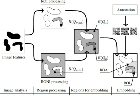
The key point for information embedding is the selection of suitable regions in the med-ical image which depend on what area was defined by medmed-ical experts as the observed
pathological region. We subdivide the image into several types of principal regionsRi, as
shown in Figure 1:
Fig. 1.Principal steps for the classification of embedding areas
1. Subareas, which contain important information. These subareas will be referred as Region of Interest (ROI) further on. It is reasonable to keep the maximal quality
Qmaxfor such type of region.
2. Subareas, which contain secondary information. They will be referred as Region of non-interest (RONI). RONI also includes the background, filling the image to the rectangular shape or capturing details of the environment. Minimal image quality
Qminis allowed for these subareas.
Target quality valuesRi(Qj)are then assigned to every regionRi. We initially
pre-sumed no information should be embedded into the ROI of an image to keep the image suitable for diagnostic purposes. Thus, we have two sets of regions: the region for the annotation embedding (Region of Annotation, ROA) and the ROI. The placing of ROA is either manual or automatic, and it accommodates the entire length of the annotation.
The ROI can be selected manually, describing image subarea with a rectangular, cir-cular or another shape that precisely selects a set of pixels of interest. Semi-automated or automated methods not always suitable to select ROI (image threshold, segmentation, clustering, etc.) as ROI is a very specific area defined by medical experts. The use of ROI for data storage purposes in medical images needs further investigations.
The design of QR codes allows quick decoding of the information when part of the carrier may be lost, but they tend to increase in size when a large amount of data is encoded. The larger the QR code, the less is the fill-factor – the ratio between the area available and the area used – of the ROA. To overcome the growth of the QR code, we split the entire annotation into the chunks and added the supporting information. It allowed keeping the size of QR reasonable and the fill-factor of the ROA in the highest level possible. Moreover, the split encoding allows arbitrary placement of the QR codes, so the ROA can take any shape and avoid the regions of the higher image quality.
The initial presumption was no information should be embedded in the principal re-gions of an image in order to keep the image suitable for diagnostic purposes. There was clear pressure on separating the region where the annotation was to be embedded (Region of Annotation, ROA) and the ROI. Based on these presumptions and the requirements de-scribed in subsection 3.2, the following image annotation scheme (Fig. 2) was developed and placed into test environment:
1. Collecting data for embedding, including entering the annotation data and specifying the region of interest.
2. Preparation of the information to be embedded, creating the embeddable block, using the annotation and geometrical properties of the ROI. This step splits the annotation into the separate substrings suitable for encoding into the QR blocks of appropriate size.
3. Encoding the data using QR codes, creating the embeddable blocks.
4. Selecting (or pointing) the region the annotations is to be embedded, i.e. ROA. 5. Preparation of image data, including any transformations of image data, needed to
embed the block into the image, like partial decoding (or partial encoding) of JPEG 2000 image data.
6. Optimal embedding the QR-encoded information into the transformed or spatial do-main, considering the size of the QR blocks and the shape of ROI.
7. Postprocessing the image data, including any manipulations on the image data, tar-geted to achieve predetermined result, like quality control, image compression or en-coding JPEG 2000 image data. This step is expected to be recursive if the information must be accessed in some particular manner (e.g. at the predefined level of detail or chromaticity).
The image can be annotated many times until the limit of the informational capacity is not reached.
It is possible to edit and remove annotation, although the removal of annotation will not restore the quality of the image. Relocation of the ROI is possible as far as its shape and size remain constant.
The annotation consists of informational fields, identifying spatial location of ROI, its shape and contents. The linear structure of the annotation is arranged in a way allowing fast identifications of ROI and its shape. After arrangement, linear structure of annotation is divided into embeddable chunks and transformed into 2D barcode widely used for labeling purposes in various fields of the industry and medicine.
Fig. 2.Developing general diagram for the embedding algorithms presented in the work
– Due to the high amount of annotating data, spatial co-location of ROA and ROI is
impossible in small areas. The annotation is embedded outside the ROI, thus leaving more space for annotations and preserving the information fidelity in the area of ROI.
– Additional fields are added to the annotation supporting the shift of ROA out ROI.
Additional metadata fields are added to the annotation structure to support shifting ROA out ROI and encoding arbitrary shape of the annotation.
– As ROI and ROA are no longer spatially related, ROA can be co-located within RONI,
allowing more information to be embedded and image distortions to happen while perceptibility is less strict in the RONI.
– Detaching ROA from the ROI allows annotating arbitrary size and shape of the ROI.
The above described framework of medical information embedding is used for both algorithms – spatial and wavelet domain based – realization.
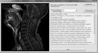
As the physical carrier of the embedded information is 2D barcode, the quality of retrieved information and possible information loss is highly dependent on the carrier. Nowadays, QR type of the 2D barcode allows restoring up to 30% of the information [23] using embedded error correction codes. In Figure 3 is given the example of the retrieved and visualized annotations that describe the ROIs of MRI head image in sagittal section.
4.
Experimental Results and Discussions
Testing of the spatial domain annotation algorithm that increases capacity for embeddable information and time of performance using the native DICOM format is presented in the 4.1 subsection. The 4.2 subsection presents testing of the annotating algorithm that saves transmission time, bandwidth, and disk space, using encapsulated DICOM format, i.e. semantic information insertion during JPEG 2000 compression.
Fig. 3.Presentation of the description for the selected ROI (highlighted) of MRI head image in the sagittal section
were used as the testbed. The length of the real textual descriptions varies from 321 to 1819 symbols.
The testing consisted of two stages. At the initial stage, series of annotated images were prepared to determine the acceptable quality level. A series contains annotated im-ages, where the annotation is embedded in every single bitplane, starting from LSB. In some cases, it was impossible to embed entire annotation imperceptibly due to the limited embedding space. Two special cases of the series were prepared, where the annotation was embedded into the entire image, including ROIs. The subjective quality metrics of every annotated image were calculated. Every series was provided to the team of clini-cal radiologists in the Institute of Oncology of Vilnius University. The expert evaluation
based on mean opinion score (M OS) was received and summed up as follows:
1. ROI, defined for pathology evaluation by experts, can not be used for information embedding.
2. Visible artifacts, due to embedded annotation into the RONI, can not be seen, as they distract attention.
3. The best choice for information embedding is the lower bitplanes from 1 to 4, some-times to 5 and 6.
According to these findings, for embedding of semantic annotations was chosen only RONI. In particular cases, when RONI is very small, ROA was selected near the edges of an object around the ROI defined by experts (an example, MRI abdominal region, sagittal
and coronal scans, Table 2), too. Acceptable image quality level was set P SN R– 80,
M S-SSIM – 0.85,IW-SSIM– 0.98.
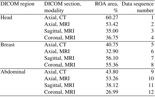
At the second stage based on the expert’s evaluations, the information capacity test
was performed, and image quality metrics were calculated for the selected 512×512 CT
and MR images (Table 2).
For objective quality evaluation, calculating statistical or visual properties of an
im-age, the state-of-the-art is structural similarity based indexes, likeSSIM,M S-SSIM
orIW-SSIM.
The overallM S-SSIM measure is computed as:
MS-SSIM=
M Y
j=1
Table 2.DICOM data for testing
DICOM region DICOM section, ROA area, Data sequence
modality % number
Head Axial, CT 60.27 1
Axial, MRI 53.42 2
Sagittal, MRI 35.00 3
Coronal, MRI 36.75 4
Breast Axial, CT 40.75 5
Axial, MRI 32.90 6
Sagittal, MRI 56.10 7
Coronal, MRI 55.36 8
Abdominal Axial, CT 43.80 9
Axial, MRI 53.26 10
Sagittal, MRI 38.12 11
Coronal, MRI 26.99 12
βjvalues were obtained through psychophysical measurement [29].
The evaluation ofj-th scaleSSIM:
SSIMj=
1
Nj X
i
c(xj,i, yj,i)s(xj,i, yj,i), (6)
forj= 1, . . . ,M– 1 and
SSIMj=
1
Nj X
i
l(xj,i, yj,i)c(xj,i, yj,i)s(xj,i, yj,i), (7)
werej=M,xj,iandyj,iis thei-th local image patches at thej-th scale, extracted from
thei-th evaluation window,Njis the number of evaluation windows in the scale.
The overallIW-SSIM measure is defined as:
IW-SSIM=
M Y
j=1
(IW-SSIMj)
βj (8)
using the same set of scale weightsβj’s as in 5.
Thej-th scaleIW-SSIM measure is computed as:
IW-SSIMj= P
iwj,ic(xj,i, yj,i)s(xj,i, yj,i) P
wj,i
, (9)
forj= 1, . . . ,M– 1 and
IW-SSIMj=
1
Nj X
i
l(xj,i, yj,i)c(xj,i, yj,i)s(xj,i, yj,i), (10)
werej=M,wj,iis the information content weight.
DenotingQas image quality function,Q(Imin)< Q(Icompressed)< Q(I),
respec-tivelyQmin < QA uQC< Q, whereQminis the minimal image quality requirements
for particular field of application,QCis the quality of compressed image andQAis the
4.1. Embedding in the Spatial Domain
The proposed algorithm in the spatial domain was verified using bitplane modifications as embedding method. Bitplanes, which start from LSB to bitplane 12 were set for em-bedding. The embedding starts at bitplane 1 (LSB bitplane), and, depending on the size of ROA, its geometrical shape and the number of atomic embedding blocks, traverses to the upper bitplanes.
The number of bitplanes for embedding plays a significant role in the embedding process. The diagnostic data in some DICOM modalities may occupy the significant area of the medical image, thus leaving almost no regions for embedding. In these cases, ROAs may interfere with the ROIs, thus slightly altering the recorded medical data. The exact amount of altered data must be selected in the way it keeps the overlying tissue substance in the same Hounsfield units (HU) scale. As some substance has very narrow HU range, this acts as the additional limiting factor for the embedding scheme, rendering additional regions of the image unsuitable for the embedding.
The resulting images were saved as 16 bit PNG image and the stated image quality metrics were calculated. Test results are presented in (Fig. 6a, 7a and 8a). Medical im-ages from the test series, the “MRI breast sagittal” and “CT head axial” scans, providing
the highest capacity considering the quality (P SN R,M S-SSIM andIW-SSIM) in
the spatial domain, are presented in Figures 4 and 5. The quality of the “CT head axial” scans with the same amount of embedded symbols is better than “MRI breast sagittal” scans (see Figures 5a and 4c respectively). There are some reasons for it. First one, the ROA area of “CT head axial” scan is 4.17% bigger than “MRI breast sagittal” scan and therefore, the one bitplane more is used for embedding in “MRI breast sagittal” scan (in total, 5 bitplanes). This result is also influenced by the shape of ROA in the spatial domain of “CT head axial” scan as it gives more space for embedding QR codes of the chosen size. Second reason, the entropy in ROA area around the CT head axial region is slightly higher than in ROA area around the MRI breast sagittal region. The higher entropy can influence better masking of embedded data. The third reason for the acquired objective
quality results is the chosen quality metrics.IW-SSIM gives the more precise
subjec-tive evaluation of image thanP SN R(see graphs of “CT head axial” and “MRI breast
sagittal” scans and compare them with subjective results in Figures 4c and 5a). The arti-facts hardly visible in all images when 100–700 words (667–4764 symbols) are embedded using spatial domain based algorithm. When the amount of the embeddable information
increases, the image quality metrics, like P SN R, decrease continuously. IW-SSIM
metrics captures subjective evaluation more precisely thanM S-SSIM and, notably, as
P SN R.IW-SSIM metrics decreases more rapidly when information capacity reaches more than 700 words (4764 symbols).
Figures 4a and 4b present better results as Figure 4c as less information was embedded and therefore fewer bitplanes were modified, from 2 to 3 respectively. Figures 5a to 5c are presented for comparison to show the further degradation of image quality when more information is embedded. The quality of the images 5b and 5c from “CT head axial” series were not taken into account when evaluating the quality of embedding, as the embedded information takes more than 9528 symbols (1400 words).
(a)500 words, 3381 symbols
(b)900 words, 6105 symbols
(c)1400 words, 9528 symbols
Fig. 4.Spatial domain, MRI Breast region, sagittal scan series
(a)1400 words, 9528 symbols
(b)1700 words, 11553 symbols
(c)2000 words, 14292 symbols
Fig. 5.Spatial domain, CT Head region, axial scan series
0 2000 4000 6000 8000 10000 30
40 50 60 70 80 90 100 110
Symbols
PSNR
CT head axial CT breast axial CT abdominal axial MRI head axial MRI head coronal MRI head sagittal MRI breast axial MRI breast coronal MRI breast sagittal MRI abdominal axial MRI abdominal coronal MRI abdominal sagittal
(a)using spatial domain based algorithm
0 2000 4000 6000 8000 10000 65
70 75 80 85 90 95 100 105
Symbols
PSNR
CT head axial CT breast axial CT abdominal axial MRI head axial MRI head coronal MRI head sagittal MRI breast axial MRI breast coronal MRI breast sagittal MRI abdominal axial MRI abdominal coronal MRI abdominal sagittal
(b)using wavelet domain based algorithm
Fig. 6.P SN Revaluation of annotated medical images (CT and MRI modalities)
as the small image is hosting relatively long annotation (see “MRI abdominal coronal” scan, 9528 symbols, ROA area – about 27%). Even for this case image quality does not
drop below ofM S-SSIM = 0.81 andIW-SSIM = 0.70. The lowest bitplanes are the
0 2000 4000 6000 8000 10000 0.55 0.6 0.65 0.7 0.75 0.8 0.85 0.9 0.95 1 Symbols MS−SSIM
CT head axial CT breast axial CT abdominal axial MRI head axial MRI head coronal MRI head sagittal MRI breast axial MRI breast coronal MRI breast sagittal MRI abdominal axial MRI abdominal coronal MRI abdominal sagittal
(a)using spatial domain based algorithm
0 2000 4000 6000 8000 10000 0.55 0.6 0.65 0.7 0.75 0.8 0.85 0.9 0.95 1 Symbols MS−SSIM
CT head axial CT breast axial CT abdominal axial MRI head axial MRI head coronal MRI head sagittal MRI breast axial MRI breast coronal MRI breast sagittal MRI abdominal axial MRI abdominal coronal MRI abdominal sagittal
(b)using wavelet domain based algorithm
Fig. 7.M S-SSIM evaluation of annotated medical images (CT and MRI modalities)
0 2000 4000 6000 8000 10000 0.5 0.55 0.6 0.65 0.7 0.75 0.8 0.85 0.9 0.95 1 Symbols IW−SSIM
CT head axial CT breast axial CT abdominal axial MRI head axial MRI head coronal MRI head sagittal MRI breast axial MRI breast coronal MRI breast sagittal MRI abdominal axial MRI abdominal coronal MRI abdominal sagittal
(a)using spatial domain based algorithm
0 2000 4000 6000 8000 10000 0.92 0.93 0.94 0.95 0.96 0.97 0.98 0.99 1 Symbols IW−SSIM
CT head axial CT breast axial CT abdominal axial MRI head axial MRI head coronal MRI head sagittal MRI breast axial MRI breast coronal MRI breast sagittal MRI abdominal axial MRI abdominal coronal MRI abdominal sagittal
(b)using wavelet domain based algorithm
Fig. 8.IW-SSIMevaluation of annotated medical images (CT and MRI modalities)
4.2. Embedding in the Wavelet Domain
Wavelet domain or wavelet transformation is a transformation, where signalf(t)is both
localized in time(u)and scale(s). Wavelet transformation is described by equation:
W f(u, s) =hf, ψu,si= Z +∞
−∞
f(t)√1
sψ∗ t−u
s dt, (11)
where hand i denotesL2-inner product; ψ ∈ L2(
R)is a wavelet – a finite impulse
response function withR−∞+∞ψ(t)dt= 0and||ψ||= 1. Theψis called ”mother wavelet”.
It is scaled inuand susing scaling functionφ so, that basic properties of ψare still
applied toψu,s:ψu,s=ψφu,s;
R+∞
−∞ ψ(t)u,sdt= 0and||ψu,s||= 1.
To get more information on the signal, pyramidical decomposition of the input signal
passed as the input signal for the next cycle of the wavelet transform. The number of pyramidical decompositions is usually referred as “decomposition levels” and marked as
Ln, where the higher level is a reduced copy of the lower level.
Wavelet transformation can be applied to any number of spaces. However, we are
interested in L2(R2) space, where image data is usually obtained and stored. For this
space, and particular for image data, discrete wavelet transformation is commonly used.
For practical reasons, discrete wavelet transformation for every scale2j and everyn =
(n1, n2)is calculated as:
aj[n] =hf, φ2j,ni;d k
j[n] =hf, ψ k
j,ni. (12)
Hereaj[n]are called approximation coefficients anddkj[n]are called wavelet coefficients.
Thek(1≤k≤3forL2(
R2)) is called subband of wavelet coefficients and denotes the
primary direction of wavelet sensitivity and are often substituted byh, v, dorLH, HL, HH
indexes respectively. In the caseLH, HL, HHindexes are used, theaj[n]is denoted asLL.
For(aj[n], dhj[n], d v j[n], d
d
j[n])∈Z, theψand, accordinglyφare selected in special way,
or quantization step is to be used.
In equation 2, for the wavelet-based algorithm, theIcare quantized indexes of DWT
decomposition,Pc are bit masks andf is a complex function of dequantization and
in-verse DWT transformation.
The standard JPEG 2000 image compression workflow is used for the information embedding into the image data, and no additional DWT decomposition and quantizations steps are performed. This approach allows reducing of calculations costs in the embedding and, especially, in the decoding stages.
The proposed wavelet-based algorithm was verified using multiple quantization index modification (QIM) approach. LeGall 3/5 wavelet is used for multi-level DWT decompo-sition, due to the usage and compression requirements.
The number of decomposition levels is limited by the resulting size of the subbands.
As the size of initial data is 512 pixels in both directions,L3was chosen as maximal level,
resulting the 64-by-64 coefficient matrices in the subbands.
After objective quality examination and considering the subjective evaluation of clin-ical radiologists, up to six bitplanes are used to embed the information in the compressed domain, as the visual distractedness of the embedded information is least perceptible.
The embedding begins at the LSB bitplane ofHH subband in the highest level of
DWT decomposition, thus exploring some peculiarities of the human visual system. De-pending on the size of ROA, its geometrical shape and the total number of embedding
blocks, the embedding traverses to more significant bitplanes,LH,HLsubbands of lower
levels of DWT decomposition, if needed. In order to minimize the influence on the image
quality,LLsubband, being the most sensitive for alternations, is not used for annotation
embedding. The annotation can be embedded into the entire tree of DWT decomposition, allowing partial image transmission and reconstruction of annotation.
Medical images from two test series, the “MRI breast sagittal” and “MRI breast coro-nal” scans, providing maximal information capacity in the wavelet domain, are presented in Figures 9 and 10 respectively. The quality of “MRI breast coronal” scans is better than
“MRI breast sagittal” scans, especially there is noticeable difference inIW-SSIMvalues
(see Fig. 8b) as visually too (compare Fig. 9 and 10). The area of ROA of these scans dif-fers only in 0.74%. For the embedding of QR codes with annotation was used lower DWT decomposition levels, 2nd and 1st, but in “MRI breast sagittal” scan were used more
bit-planes ofHLsubband for embedding in 1st level. The shape of ROI region of “MRI breast
coronal” scans is more even than of “MRI breast sagittal” scans. It had the influence for the embedding space in DWT decomposition levels (for the given case more space at 1st level).
(a)500 words, 3381 symbols
(b)900 words, 6105 symbols
(c)1400 words, 9528 symbols
Fig. 9.Wavelet domain, MRI Breast region, sagittal scan series
(a)500 words, 3381 symbols
(b)900 words, 6105 symbols
(c)1400 words, 9528 symbols
Fig. 10.Wavelet domain, MRI Breast region, coronal scan series. Image data rescaled to reveal the impact
The results reveal the weak influence of the embedded information to the visual ap-pearance of the image when the amount of embedded information is relatively low (100 – 200 words or 667 – 1341 symbols). When the amount of the embeddable information increases to approximately to 400 words (2684 symbols), the ratio-based image quality
-SSIM, tend to show better results. The comparative evaluation of experts shows the
IW-SSIM metrics captures subjective evaluation more precisely thanM S-SSIM and
P SN R.
Compared to the embedding in the spatial domain, DWT approach provides less space for the embedding, especially for the smaller images, having bigger areas for significant parts (see “MRI head sagittal”, “MRI abdominal coronal” and “CT breast axial” series in Fig. 6b and Fig. 8b). As the size of embedding block is fixed, it is not uncommon the em-bedding begins on the 2nd or the 1st levels of DWT decomposition as there is no physical space to fit the entire embedding block in the upper levels of DWT decomposition. As a result, the embedded information is more visible in the final image and tends to distract attention slightly more. The limited embedding space decreased the maximal length of the embedded information, although the amount of embedded information – 500 words or 3381 symbols is higher the average length of the presented descriptions of about 1000 symbols.
The results reveal the high importance of the geometrical shape of the ROA as the square shape of the embedding block must fit a small and rather a random area of the
region. The utilization factor of the ROA,kucan be expressed as
ku=
AROA Pn
1Ablockn
, (13)
whereAROAis the total area of the ROA,nis the number of embedded block andAblock
is the area of a single block of information.
The equation 13 should be solved formax(ku), varying theAblock.
5.
Conclusions and Future Work
In this paper, the medical image annotating algorithms for embedding semantic descrip-tions about corresponding ROIs directly into RONI of image content in the wavelet and spatial domains are proposed. The annotation algorithms are based on comparative anal-ysis of capacity considering the optimal embedding of QR codes with structurized infor-mation chunks and acceptable quality level.
As seen from experiments, it is possible to embed the real description into the JPEG 2000 encoded medical image, as well as into spatial domain using native DICOM format and retrieve it. The amount of embedded annotation, preserving the acceptable image quality is higher the average length of the presented descriptions of about 1000 symbols. The wavelet-based approach provides less space for the embedding compared to the embedding in the spatial domain, especially for the smaller images, having bigger areas of ROA. Fill-factor and the length of embedded information are the primary factors for the appearance of visible artifacts in an image. No more than half of the available bitplanes should be used for information embedding, both in spatial and wavelet domains. Lower bitplanes are preferred over the higher ones when embedding is performed in the wavelet domain.
The quality of annotated images using wavelet-based algorithm degrades slightly more when compared to the embedding in the spatial domain.
The comparative evaluation of experts shows theIW-SSIM metrics captures
Future experiments will be directed at the development of an annotation algorithms using lossy compression standards (JPEG and JPEG 2000) and their evaluation in com-parison to the article presented annotation algorithms. JPEG format is motivated as it is encapsulated DICOM format and widespread among various users.
References
1. Al-Dmour, H., Al-Ani, A., Nguyen, H.: An efficient steganography method for hiding patient confidential information. In: Proc. of the IEEE International Conference on Engineering in Medicine and Biology. pp. 222 – 225 (2014)
2. Anastassopoulos, G.K., Skodras, A.N.: JPEG 2000 ROI coding in medical imaging application. In: Proceedings of the 2nd IASTED International Conference on Visualisation, Imaging and Image Processing. pp. 783–788 (2002)
3. Chen, J.H., Chen, W.Y., Chen, C.H.: Identification Recovery Scheme using Quick Response (QR) Code and Watermarking Technique. Applied Mathematics & Information Sciences 8(2), 585–596 (2014)
4. Chen, W.Y., Wang, J.W.: Nested image steganography scheme using QR-barcode technique. Optical Engineering 48(5) (2009)
5. Coatrieux, G., Lecornu, L., Sankur, B., Roux, C.: A review of image watermarking applications in healthcare. In: Proceedings of the 28th IEEE Engineering in Medicine and Biology Society. pp. 4691–4694 (2006)
6. Cruz-Roa, A., Díaz, G., Romero, E., González, F.A.: Automatic annotation of histopatholog-ical images using a latent topic model based on non-negative matrix factorization. Journal of Pathology Informatics 2(2), 4–13 (2011)
7. Digital imaging and communications in medicine (DICOM). part 5: Data structures and encod-ing. Rosslyn, USA (2011), ftp://medical.nema.org/medical/dicom/2011/11_05pu.pdf
8. Eswaraiah, R., Reddy, E.S.: Medical image watermarking technique for accurate tamper detec-tion in ROI and exact recovery of ROI. Internadetec-tional Journal of Telemedicine and Applicadetec-tions (2014)
9. Giakoumaki, A., Pavlopoulos, S., Koutsouris, D.: Multiple image watermarking applied to health information management. IEEE Transactions on Information Technology in Biomedicine 10(4), 722–732 (2006)
10. He, S., Kirovski, D., Wu, M.: High-fidelity data embedding for image annotation. IEEE Trans-actions on Image Processing 18(2), 429–435 (2009)
11. Hore, S., Bhattacharya, T., Bhadra Chaudhuri, S.R.: A Robust Medical Image Authentication Technique using QR Code and DWT. International Journal of Computer Applications 83(16), 21–26 (2013)
12. Jiao, S., Goutte, R.: A secure transfer of identification information in medical images by steganocryptography. International Journal of Communications, Network and System Sciences 3, 801–804 (2010)
13. Jithin, V.M., Gupta, K.K.: Robust invisible QR code image watermarking in DWT domain. International Journal of Electronics and Communication Engineering & Technology 4(7), 190– 195 (2013)
14. Kadam, S.T., Bajpai, S., Yelmar, P.M.: Annotation: an investigative survey of annotation. In: Proceedings of the International Conference on Advances in Engineering and Technology. pp. 102–105. Rakesh Kumar, Roorkee, India (2014)
16. Kannammal, A., Pavithra, K., SubhaRani, S.: Double Watermarking of DICOM Medical Im-ages using Wavelet Decomposition Technique. European Journal of Scientific Research 70(1), 46–55 (2012)
17. Kazakeviˇci¯ut˙e, G., Januškeviˇcius, E., Rosenbaum, R., Schumann, H.: Self annotated raster im-age. Information Technology and Control 35(2), 106–116 (2006)
18. Kim, M., Li, D., Hong, S.: A robust digital watermarking technique for image contents based on DWT-DFRNT multiple transform method. International Journal of Multimedia and Ubiquitous Engineering 9(1), 369–378 (2014)
19. Lee, H.K., Kim, H.J., Kwon, K.R., Lee, J.K.: ROI Medical Image Watermarking Using DWT and Bit-plane. In: Proceedings of Conference on Communications. pp. 512–515. Perth, Western Australia (2005)
20. Manasrah, T., Al-Haj, A.: Management of medical images using wavelets-based multi-watermarking algorithm. In: Proceedings of the International Conference on Innovations in Information Technology. pp. 697–701. IEEE, Al Ain, JAE (2008)
21. Nagaraju, C., ParthaSarathy, S.S.: Embedding patient information in medical images using LBP and LTP. Circuits and Systems: An International Journal 1(1), 39–48 (2014)
22. Punien˙e, J., Navickas, R., Punys, V., Jurkeviˇcius, R.: Statistinis tyrimas medicininiu˛ vaizdu˛ sus-paudimui ”bangeliu˛” transformacijos metodu i˛vertinti (statistical investigation of the wavelet-based lossy medical image compression technique). Medicina 38(2), 210–213 (2002) 23. Types of QR code (2014), http://www.denso-wave.com/qrcode/vertable1-e.html
24. Shiao, Y.H., Chen, T.J., Chuang, K.S., Lin, C.H., Chuang, C.C.: Quality of compressed medical images. Journal of Digital Imaging 20(2), 149–159 (2007)
25. Sung, M.M., Kim, H.J., Yoo, S.K., Choi, B.W., Nam, J.E., Kim, H.S., Lee, J.H., et al.: Clinical evaluation of compression ratios using JPEG 2000 on computed radiography chest images. Journal of Digital Imaging 15(2), 78–83 (2002)
26. Wang, Z., Bovik, A.C.: A universal image quality index. IEEE Signal Processing Letters 9(3), 81–84 (2002)
27. Wang, Z., Bovik, A.C., Sheikh, H.R., Simoncelli, E.P.: Image quality assessment: from er-ror visibility to structural similarity. IEEE Transactions on Image Processing 13(4), 600–612 (2004)
28. Wang, Z., Li, Q.: Information content weighting for perceptual image quality assessment. IEEE Transactions on Image Processing 20(5), 1185–1198 (2011)
29. Wang, Z., Simoncelli, E.P., Bovik, A.C.: Multi-scale structural similarity for image quality assessment. IEEE Asilomar Conference on Signals, Systems and Computers 2, 1398–1402 (2003)
30. Wu, D., Tan, D.M., Baird, M., DeCampo, J., White, C., Wu, H.R.: Perceptually lossless medical image coding. IEEE Transactions on Medical Imaging 25(3), 335–344 (2006)
Gir ¯uta Kazakeviˇci ¯ut˙e-Januškeviˇcien˙ereceived the Ph.D. degree in Technological Sci-ences from Vilnius Gediminas Technical University (VGTU) in 2001. She is currently working an Associate Professor in the Department of Graphical System, VGTU. Her cur-rent research interests include image processing and analysis, information hiding, image annotation.
Andrius Ušinskasreceived Ph.D. in 2003 from Vilnius Gediminas Technical University. He is currently working as Professor in Department of Electronic Systems. His research interest is image analysis, processing, and recognition.
of Architecture. His research interests include building information modeling (BIM), im-age analysis and interdisciplinary approach to the problem solving.
Jurgita Ušinskien˙e received Ph.D. in 2007 from Vilnius University. She is currently working as the researcher at National Cancer Institute. Her research interest is neuro-radiology and analysis of brain tumor.
Simona R ¯uta Letautien˙ereceived Ph.D. in 2006 from Vilnius University. She is currently working as Associate Professor in Vilnius University, Medical Faculty and Consultant Radiologist in the Department of Radiology at National Cancer Institute. Her research interest is oncoradiology and analysis of cancer diagnostic imaging.