Capability-oriented Architectural Analysis Method
Based on Fuzzy Description Logic
Zhang Tingting1, Liu Xiaoming2
, Wang Zhixue2, Dong Qingchao3
1Software Engineering Department PLA University of Science and Technology, 210017 JiangSu, NanJing, China
2Technology of Command and Control Department, PLA University of Science and Technology 210017 JiangSu, NanJing, China
3
Naval Aeronautical and Astronautical University 264000 YanTai, China
Abstract. A number of problems may arise from architectural requirements modeling, including alignment of it with business strategy, model integration and handling the uncertain and vague information. The paper introduces a method for modeling architectural requirements in a way of ontology-based and capability-oriented requirements elicitation. The requirements can be modeled within a three-layer framework. The Capability Meta-concept Framework is provided at the top level. The domain experts can capture the domain knowledge within the framework, forming the domain ontology at the second level. The domain concepts can be used for extending the UML to produce a domain-specific modeling language. A fuzzy UML is introduced to model the vague and uncertain features of the capability requirements. An algorithm is provided to transform the fuzzy UML models into the fuzzy Description Logics ontology for model verification. A case study is given to demonstrate the applicability of the method.
Keywords: Description Logics; Enterprise Architecture; Fuzzy UML; Fuzzy Model Checking; Ontology.
1.
Introduction
However, the real world is full of uncertain and imprecise information which is hard to model, particularly for the efficiency features of the C4ISR capability requirements. Such features cannot be modeled with standard UML. For example, a statement “we need a fast vehicle” expresses a vague requirement for the Maneuver capability. Here, fast is an uncertain and imprecise concept of efficiency. You may simply define an attribute speed for the class vehicle, but soon find it difficult to determine the quantity.
On the other hand, as a semi-formal modeling language, UML does not support formal specification and verification. While the DoD Architecture Framework provides meta models for architectural modeling constructs and rules, there are no rigid definitions and formal specifications for them. This leads to difficulty in checking the models of different viewpoints.
To solve the problem and enable automatic model checking with reasoning technique, the paper presents a technique of capability requirements modeling and verification. It extends the UML modeling constructs with the Meta Model of DoDAF so that requirements models can be built within the standard framework. A fuzzy UML is introduced so as to model the fuzzy efficiency features of capabilities. To enable automatic model checking, we present a three-layer framework for modeling C4ISR capability requirements and provide an algorithm to convert the fuzzy UML models into the ontology specified in fuzzy Description Logic (f-DL), so that the built model can be checked for consistency and reasonability through logical inference.
The rest of the paper is organized as follows. Section 2 discusses in detail a domain reusable and vague enable modeling method for the capability requirements elicitation and architectural analysis. Section 3 provides an algorithm converting the capability requirements models into the knowledge base in the f-DLs system to enable automatic model checking. The last section demonstrates the applicability of the method by analyzing an example of an Air Surveillance & Warning system.
2.
Related Work
This work is most closely related with prior art in the following three categories: complex system modulation, enterprise/requirements modeling and formal specification and verification.
2.1. Complex System modulation
C4ISR is a complex information system consists of a set of large-scale, concurrent and distributed system. The methods of modeling and simulation of complex systems include: complex network theory and discrete-event system simulation etc.
series of other systems, and proposed a modeling method able to reflect the C2 function through a network of geographically-distributed entities. This modeling process preliminarily classifies the C2 function as data collection, data analysis and data planning, and explores how these C2 function are indicated through network modeling in different C2 methods.
Simulation methods based on Petri nets and a variety of extended Petri nets (i.e.: CPN, OPN, etc.) are a widely used discrete-event system simulation method [5]. Such methods need to convert the system model into corresponding Petri nets model. Thus, the modeling language and type of the targeted Petri net model determine and affect the application of the simulation method.
2.2. Requirements modeling
It is argued that the capability-oriented thinking is a robust enterprise architecture strategy for the successful SOA (service-oriented architecture) solution, for “it can abstract the stable from the volatile, encapsulate the volatile within services and manage change through the information system requirements evolution” [6]. Besides, in a capability model, an enterprise service model (ESM) is proposed to map services in an IT solution to capabilities [7].
To enhance software development to the level of hardware development, NASA is using model-based languages (such as SequenceL [8]) and risk analysis methodologies. It also hopes to achieve a fusion between systems and software engineering by replacing conventional software development techniques with capability engineering which focuses on a system’s full set of functionalities [9].
In [10], the Formal Design Analysis Framework (FDAF) is proposed for software architecture modeling to bridge the gap between enterprise and early software models (requirements and architecture). Meanwhile, the authors utilize an UML business modeling extension [11] to model the business goals and standard UML use cases, so as to analyze the software requirements.
Jeffrey et al. [12] claims that a formal requirements specification language plays an important role in software development. The experiences gained from the FRORL project is reported, and they also state the value of research in knowledge-based software engineering in verification, validation, requirements analysis, debugging, and transformation.
It has been found by Kang et al. [13] that, the enterprise model cannot express the semantics enough. Meanwhile, they define the fact-based ontologies, through which the relationships can be defined and reasoned semantically.
2.3. Formal specification and verification
By exploiting the formal techniques by a round trip mapping of KAOS [14] requirements level notations to the languages of formal V&V tools, Ponsard et al. [15] present an integrated toolbox (named FAUST formal toolbox) to ensure at an early stage that the right system is being built and the requirements model is right.
As Chapurlat et al. [16] suggests enterprise modeling should be made in three processes: conceptualization, modeling and verification. First, in the conceptualization process, the domain expert captures the domain knowledge in the Properties Reference Repository, defining a formal ontology for the selected domain. Second, in the modeling process, the user models the enterprise using UEML [17] and specifies the properties corresponding to the needs he or she wants to verify, using the domain ontology. And finally, in the verification process, the user will then prove some chosen properties on the model by making use of formal mechanisms, allowing him to increase his own knowledge and improve the model’s quality and relevance.
Floch et al. [18] propose a model-driven development approach, in which they combine UML modeling and ontology techniques to specify and validate software component properties and a middleware platform which supports component discovery, compatibility checking and deployment.
However, the aforementioned approaches and techniques do not address uncertain domain modeling and specification. As a result, they cannot be used to reason on fuzzy knowledge. As for our approach, we leverage a fuzzy extended UML (fuzzy UML) to cope with fuzzy concepts for the complex objects, so that both the function and non-function features of SoS requirements can be modeled. Additionally, we propose an effective algorithm to convert the fuzzy UML models into the ontologies described in f-SHIN to enable model verification through the logic inference mechanism.
3.
Domain Reusable Capability Requirements Modeling
3.1. A three-tier modeling framework
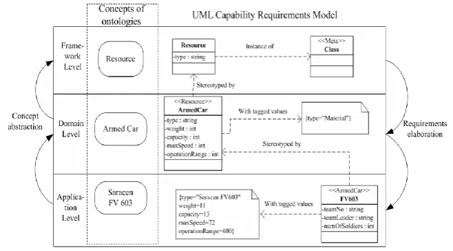
As introduced above, we adopt both ontology and UML techniques to model the enterprise architecture. The enterprise requirements analysis and architecture development is processed in two phases and the capability requirements are modeled within the three layered modeling framework. The figure 1 gives an example of how the domain concept ArmedCar of the capability requirements to be modeled referencing up to the Meta concept Resource and reusable down to the application concept Saracen FV603.
framework (CMCF) providing guidelines and constraints for capability requirements modeling and architecture design. They can be applied as new constructs to extend a universal modeling language to improve its domain applicability and specialty.
Fig. 1. An example of the conceptual modeling within the three-layer framework
The second layer, the domain level, reflects the domain-specific concepts. For the domain of army command and control management, for example, the ArmedCar (shown in figure 1) is a domain concept of capability requirements featured by the type of vehicle used in the army operation and attributes like weight, capacity, maximum speed and operation range of the armed car. Those domain-specific concepts form the domain ontology which functions as: (1) being the modeling constructs and constraints to improve the applicability of the modeling language for capability requirements modeling; (2) explaining the semantics of both function and efficiency features of capability requirements in either certain or vague concepts of the domain knowledge; (3) prescribing the guidelines or rules for modeling the application requirements.
The third layer reflects the application concepts of the capability requirements, which results in the final products of capability requirements analysis. The concepts at this layer are related to real objects and stereotyped by the domain concepts. For example, Saracen FV603 (shown in figure 1) is an application concepts stereotyped by the domain concept ArmedCar with the attributes valued like weight of 11 ton, capacity of 13 people, maximum speed of 70 kilometers and operation range of 400 kilometers. The software engineers make use of the domain concepts to model the real world needlessly worrying that they lack of domain knowledge while focusing on elicitation of the application requirements such as how many soldiers would be in the operation and who be the team leader.
modeling language and model the application with the domain-specific modeling language.
To enable semantic checking, we formalize the requirements models using f-SHIN, the subsystem of fuzzy Description Logics, which is powerful in expressivity and decidability for a knowledge system. The model checking can guarantee the application requirements models semantically consistent with enterprise architectural concepts and domain concepts. Furthermore, the fuzzy inference system can find out deficiency of the capability requirements due to the unsatisfied efficiency features, for example, an anti-missile mission will impossibly be committed because of the limited operational range of the warning system.
The following passage gives formal definitions of the capability meta-concept framework and the domain ontology, and explains the modeling and verification mechanism.
3.2. Capability meta-concept framework
Definition 1: the capability meta-concept framework (CMCF) is composed of three parts, <MetaConcept, MetaAssociation, MetaRule>.
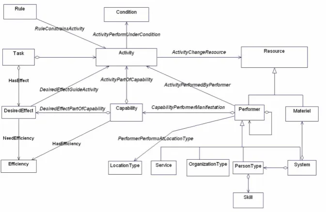
MetaConcept is a finite set of concepts which contains all capability related meta-concepts from the CMM [1], such as Activity, Capability, Task, Resource, Performer etc., and which keep the same semantics as those in the CMM. The figure 2 shows those meta-concepts in MetaConcept.
MetaAssociation is a finite set of relations which contains all capability related meta-relations from the CMM, such as DesiredEffectPartOfCapability, ActivityPerformedByPerformer, RuleConstrainsActivity etc., and which keep the same semantics as those in CMM. The figure 2 shows those meta-relations in Meta Association.
Fig. 2. A sample of capability meta-concept framework
3.3. Domain knowledge acquisition
Domain ontology for capability requirements. The meta-concepts like Performer in the CMCF are still too abstract and have little domain meanings. The capability requirements are necessarily modeled with domain concepts like Radar Unit. Those concepts are captured in the domain ontologies, forming the domain knowledge base. The concepts and relations of the ontologies are domain concretion (instantiation) of the CMCF. To enable fuzzy information modeling, we introduce fuzzy sets of the concepts and relations.
Definition 2: the domain ontology is composed of four parts: <DomConcept, DomAssociation, DomFunction, DomConstraint>.
DomConcept is a finite set of domain-specific concepts, every of which is defined by a unique meta-concept of the CMCF. DomConcept should satisfy such conditions:
DomConcept = DomPreciseConcept UDomFuzzyConcept; e: Concept [0, 1], where each e is an instance defined by a Concept which is a member of DomConcept;
DomPreciseConceptDomFuzzyConcept = , where the DomPreciseConcept is a finite set of the certain concepts, e.g. AdvancedMobility, and the DomFuzzyConcept is a finite set of the uncertain concepts, e.g. a wide operational scope and a fast moving speed.
fuzzy UML. DomAssociation should satisfy such a condition r: Association [0, 1], where each r is an instance defined by an Association which is a member of DomAssociation.
DomFunction is a complete function, specifying the mappings from DomConcept to MetaConcept or from DomAssociation to MetaAssociation. It is used for tracing the type of domain concepts or relations in the CMCF.
DomConstraint is a finite set of domain model constraints specified in fuzzy Description Logics according to the rules of MetaRule.
Enhanced OO Modeling Technology. To model the C4ISR capability domain and
build the fuzzy domain ontology, we adopt the extended fuzzy UML to describe the uncertain domain-specific concepts.
According to the literature 3, we can specify a domain-specific modeling language by extending the Meta Object Facility (MOF) of UML with CMCF. Accordingly, the new stereotypes are defined by the concepts such as Performer, Capability, System etc., and the new association stereotypes are defined by the relations such as ActivityPartOfCapability, RuleConstraintActivity etc.
The certain domain concepts, usually describing the functional features of capability requirements, can be modeled as ordinary UML classes stereotyped by the CMCF concepts such as Capability, while the uncertain domain concepts, usually describing the efficiency features, can be modeled as either fuzzy UML classes stereotyped by the CMCF concepts such as DesiredEffect. Moreover, the domain constraints can be specified as fuzzy DL expressions. As the mappings of the domain concepts to the CMCF concepts have been built in the models, the model verification can be easily made against the CMCF ontology through logic reasoning, provided that they can be transformed into ontology models specified in fuzzy DL.
Capability requirements modeling. The domain model captures the domain concepts
which describe the requirements from user perspectives. But the application requirements involve more concrete description. For example, the general concept Warning Radar needs to be instantiated as Type-Y Radar with attribute specified in the application, e.g. equipmentID, numOfOperator and so on.
In the UML models of capability requirements for an application, the things of the problem world are conceptualized with the application-level defined concepts which are stereotyped either by the domain-level concepts, or by the framework-level concepts if the user finds no such domain concepts available to map the application concepts. Those application concepts can be used for building the capability application ontology, which is then used for checking the model integrity.
Definition 3: The capability application ontology for an application system is composed of three parts: <AppConcept, AppAssociation, AppFunction >.
AppConcept is a finite set of application-level defined concepts, every of which is defined either by a unique concept of the domain ontology or by a unique concept of CMCF.
AppFunction is a complete function, specifying the mappings from AppConcept to
MetaConcept U DomConcept or from AppAssociation to MetaAssociation U DomAssociation.
Definition 4: the function type is a total function, mapping the concepts and relations of the capability requirements model to the corresponding type of UML constructs.
Definition 5: the function multiplicity is a total function, indicating how many instances may fill an association in a UML model.
The domain concepts/relations modeled as classes/associations now become the stereotypes for the application class and association, with the tags which specify the attributes and assigned values of the instance of the domain class or association. By reusing the domain ontologies, the engineers are able to model both functional and non-functional features of the application requirements and analyze whether the built models satisfy the domain constraints or whether the designed systems can achieve the desired effect with the model checking technique as discussed in next section, needlessly worrying about lack of domain knowledge.
4.
Capability Requirements Model Conversion and Verification
4.1. Two kinds of verification
The model verification can be classified into two kinds: consistency checking and rationality checking. The consistency checking is to examine whether the capability requirements model built is consistent with both the architecture framework CMCF and the domain ontology, or more specifically, whether the concepts of application models, typed by the domain-specific concepts or CMCF concepts, break the domain-specific constraints or CMCF rules declared by the ontologies. Such checking may also solve the interoperability issue, since all related models will be converted into ontologies which comprise a knowledge base, where logic inference can be made to check the whole requirements.
The rationality checking is to examine whether the model has some unreasonable efficiency features, i.e. some efficiency features do not meet the needs of the mission. It could be a useful tool for making a decision in the phase of system integration.
4.2. Fuzzy ontology and Fuzzy Description Logic
Ontology constitutes a key component of domain knowledge re-usability and high interoperability. Two-valued-based logical methods are insufficient to handle ill-structured, uncertain or imprecise information encountered in real world knowledge. A tolerance for imprecision by a positive use of Fuzzy Logic may be exploited to enhance the power of knowledge representation [24]. It has been shown that Fuzzy Logic allows bridging the gap between human-understandable soft logic and machine-readable hard logic. Indeed, there has been a natural integration of Fuzzy Logic in ontology in order to define a new theoretical paradigm called Fuzzy Ontology [25].
Description Logics (DLs) are a logical reconstruction of the so-called frame-based knowledge representation languages, with the aim of providing a simple well-established Tarski-style declarative semantics. Essentially, DLs are the theoretical counterpart of the Web Ontology Language OWL DL, and play a particular role in the representation and inference of ontologies. In order to deal with the vagueness knowledge, some related works have extended the DLs with Fuzzy Logic [26-28]. In our research, we choose f-SHIN, the subsystem of fuzzy DL, to describe the capability requirements, because it is powerful in expressability and decidability for a knowledge system and allows to make use of some handy inference engines like Pellet and Racer [28].
4.3. Model transformation
Ma et al. [29, 30] present a way of translating a fuzzy UML model into the f-DLs knowledge base and reasoning on f-DLs. The underlying principle includes: (1) translating the fuzzy UML models into the f-DLs knowledge bases (f-DLs TBox) at terminological level; (2) translating the fuzzy UML instantiations (i.e., object diagrams) with respect to fuzzy UML models into the f-DLs knowledge bases (f-DLs ABox) at assertion level. Upon their work, we provide an algorithm as follows to convert the capability requirements models into the capability knowledge base according to the definitions introduced before.
Algorithm: convert a capability requirements model into the capability knowledge base.
Input: the CMCF; domain ontology; the capability requirements model
Output: the capability knowledge base Step1: extending the domain concepts
Step2: creating the concepts and their instances.
Step3: establishing the relationships between the concepts and instances. Step4: specifying the domain rules.
The end
CMCF meta-concepts need to be added to the domain ontology and a class hierarchy to be established.
Step 1.1: combining the domain ontology with the CMCF.
NewDomainConcept = MetaConcept U DomConcept,
NewDomainAssociation = MetaAssociation U DomAssociation.
Step 1.2: creating generalization relationships between them. For every domain concept
dom
C DomConceptand DomFunction (Cdom) = Cmeta, add a new relationship
R(Cmeta,Cdom) in the NewDomainAssociation and set the mapping function Type(R) = generalization.
Creating the concepts and their instances. The knowledge base is built by creating the concepts and their instances respectively in Tbox and Abox and establishing the relationship between them.
Step 2.1: creating concepts. For every definite concept C
NewDomainConcept, create a same name concept C in TBox T. If concept C has an attribute Att and the range of Att is P, then create a same name concept P and a relation Att, and add an axiomCAtt P. into the TBox T. If the attribute has a multiplicity, multiplicity(Att) = [i…j], add an axiom CiAtt jAtt;For every fuzzy concept FC
NewDomainConcept , create a same name concept FC in TBox T and specify its fuzziness in following way:1) The μ at the first level of fuzziness is implicitly defined in the fuzzy concept; 2) At the second level of fuzziness, the fuzzy attribute named Att, owned by a
fuzzy concept FC and of type C, is defined by an axiomFCAtt C. . If the attribute has a multiplicity(Att) = [i…j], add an axiom FCiAtt jAtt. 3) The third level of fuzziness is defined by the Step 3.2.
Step 2.2: creating instances. For every object o
AppConcept which is mapped by AppFunction(o) = C to a definite domain concept C with an attribute Att valued a, create the same name instances o and a in the ABox A, specify the class-of relationship between C and o, and add the assertions <o: C = 1> and <(o, a): Att = 1>;For every object o
AppConcept which is mapped by AppFunction(o) = FC to a fuzzy domain concept FC with an attribute Att valued a where the objects membership degree is n and the attribute membership degree is m (
, , ,
, n and m arebetween 0 and 1), create the same name instances o and a in the ABox A, specify the class-of relationship between C and o, and add the assertions <o: FC n> and <(o, a): Att m>.
Establishing the relationships between the concepts and instances. There are three types of relationships in the requirements model: association, generalization and aggregation. The conversion will be done in following steps.
Step 3.1: dealing with association relationship. For every domain relation
R A, B( )NewDomainAssociation typed by the function Type(R) = association (i.e., R is a
AR.B;BR .A- ;AmbRnbR; BmaR
naR.For every instance relation r (a, b) AppAssociation typed by the function AppFunction(r) = R and Type (R) = association where the possibility of the relation r(a, b) isn, add such assertion in the ABox A as <(a, b): Rn> and <(b, a): R-
n >.
Step 3.2: dealing with generalization relationship. For every domain relation
R A, B( )NewDomainAssociation typed by the function Type(R) = generalization (i.e.,
B is a subclass of A), create in the TBox T the relation SubConcept and add in TBox T such axioms: BA; BSubConcept A
.
.For every instance relation r (a, b) AppAssociation typed by the function AppFunction(r) = R and Type (R) = generalization where the possibility of the relation r(a, b) isn, add such assertion in the ABox A as <( b, a): SubConcept n>.
Step 3.3: dealing with aggregation relationship. For every domain-specific relation
Agg A, B( )NewAssociation typed by the function Type (Agg) = aggregation (i.e., A is aggregate part, B is constituent part), if B are fuzzy classes with cardinality constraints (m,n), create in TBox T the same name relations Agg with the reversed relation Agg
where AggAgg and add in TBox T such axioms as:
m n
AAgg.Bu Aggu Agg;BAgg .A_ u1Agg_ u1Agg_.
For every application relation agg (a, b) AppAssociation typed by the function AppFunction(agg) = Agg and Type(Agg) = aggregation where the possibility of the relation r(a, b) isn, add such assertion in the ABox A as < ( a, b): Agg n >; < ( b, a ):Aggn >.
Specifying the domain rules for model checking. The domain checking rules can be formally specified as the cardinality restrictions imposed on the instance associations of meta-concepts. To explain the rule-base construction algorithm, we classify those rules into two categories so as to handle them respectively.
Step 4.1: specifying the Qualified Cardinality Restriction (QCR) rules. The QCR rules are expressed as: x C x. 1( )
#
y C y| 2( )R x y( , )
1
. The examples of suchrules are like: each Capability must be the result of one or more Activities; each Organization must be the Performer of one or more Activities; etc.
Step 4.2: specifying the Constant Cardinality Restriction (CCR) rules.
The CCR rules are the strictest meta rules, expressed as:
1 2
. ( ) # | ( ) ( , )
x C x y C y R x y n
. The examples provided by DoDAF are like:
each Materiel must be used by one or more Persons, where each Person must be the member of only one Organization at a certain time; etc. Based on the above classification, the domain-general rules are added in f-SHIN system in following way, forming the domain-general rule base.
Step 4.3: constructing the rule base. For every Type (Rule(R(C1,C2))) = QCR, add
Through the above steps, the capability requirements knowledge base can be built. Such knowledge base comprises all the concept of three levels and is used for verifying the capability requirements models through logic inference. Similarly, the domain knowledge base which is composed of the CMCF concepts and domain concepts can be established from the domain models through step 2 to 4, and the domain model can be verified.
4.4. Automating verification using existing reasoning engines
The model verification can be made by checking the knowledge base consistency and rationality, and the process can be automated by applying the existing Description Logic reasoning engines such as Pellet [31,32].
Bobillo et al. [33] also present the DeLorean (Description Logic REason with vAgueNess) system, a reason that supports a fuzzy extension of the DL SROIQ [34] under Zadeh semantics. They show that a fuzzy DL SROIQ knowledge base (KB) can be reduced into a crisp KB, and the procedure preserves reasoning under Zadeh semantics so that existing reasons such as FaCT++ and Pellet could be applied to the resulting KB.
5.
A Case Study
5.1. Introduction
To examine the proposed approach, we lead a pilot study on architectural design for a large-scaled C4ISR system of city air defense. There are thousands of key concepts in the capability requirements, many of them relating to both functional and non-functional features and being vague and imprecise. Those concepts might be misunderstood among engineers or between the engineers and stakeholders, which may hinder building the system architectures. The models in following sections concentrate on a few of them, such as the capability of early warning, the capability of anti-air preparation, and importance of the objects protected, which are critical to the mission of city air defense and which are likely to cause misunderstanding.
5.2. The domain model and fuzzy efficiency evaluation functions
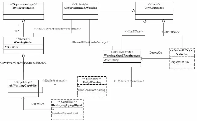
The Air Surveillance & Warning (ASW) system is a system of the complex C4ISR system of city air defense. A fragment of the domain model of ASW system is shown in the figure 3. The air surveillance and warning activity is performed by the Warning Radar which belongs to the Intelligent Station and which has an Air Warning Capability to perform the activity. The capability is featured by a fuzzy efficiency concept Early Warning, one of the indicators for measuring whether the activity can be executed satisfying the mission effectiveness specified in the Warning Ahead Requirement. The concept Early Warning describes how early the flying objects can be recognized for the air defense force to get fully prepared for action on them before they may endanger the protected area, and therefore the time consumed in identifying the flying object and judging its danger is modeled as an attribute to it. The air defense activity is performed by an anti-air missile system (not presented in the diagram), which has a DestroyingFlyingObject capability. The capability is also a fuzzy concept and has an attribute named timeForPrepared. Another fuzzy concept is the Protection of DesiredEffect, describing the effect of protection such as whether the important object protected is damaged, and hence the importance is modeled as an attribute to it. Those fuzzy concepts can be modeled as fuzzy classes.
Fig. 3. An example of the city integrated air defense domain model
To determine the objects membership degrees u, we introduce an important concept, fuzzy efficiency evaluation functions (FEEFs). For this case, three FEEFs are defined. The fuzzy objects membership degree u of the class Early Warning is calculated with the function:
1-0.01t 0 t 100min Early(t)=
0 t 100 min
where t is a variable representing the time consumed in identifying the flying object and judging its danger, the constant 100 is the maximum minutes for an air defense force to commit a mission, and the fuzzy coefficient 0.01 is given by the domain experts. If0 t 100 min utes, Early(t) generates a valid fuzzy efficiency value which describes the degree of Early Warning. Otherwise, it generates 0 representing an invalid time variable entered or the mission failure.
5.3. The application model and knowledge base
The capability requirements model built at application-level is shown in figure 4. The EW-SystemX, a concrete concept of Early Warning for the system X, is stereotyped by the domain concept Early Warning, with the tagged values timeConsumed=20 and fuzzy objects membership degree u=0.8 calculated by the FEEF Early(t). TypeXMissile, a concrete concept of DestroyingFlyingObject capability, is stereotyped by the domain concept DestroyingFlyingObject, with the tagged values timePrepared=15 and fuzzy objects membership degree u=0.8 calculated by the FEEF Preparation(t). ProtectionA and ProtectionB, the concrete concepts of Protection, are stereotyped by the domain concept Protection, with the tagged values importance=1 and fuzzy objects membership degree u=0.9 calculated by the FEEF important(x).
The capability requirements models is converted into the knowledge base, which is composed of the concepts, relations, instances, axioms and assertions.
Concepts: Task, Rule, Performer, Activity, Capability, Efficiency, OrganizationType (OT), DesiredEffect (DE), IntelligentStation (ID), WarningRadar (WR), AirWarningCapability (AWC), AirSurveillance&Warning (ASW), EarlyWarning (EW),
CityAirDefense(CAD), WarningAheadRequirement (WAR), Protection,
DestroyingFlyingObject (DFO).
Relations: ActivityPerformedByPerformer (APBP), RuleConstraintsActivity, (RCA), ActivityPartOfCapability (APOC), DesiredEffectGuideActivity (DEGA), DesiredEffectPartOfCapability (DEPOC), PerformerCapabilityManifestation (PCM) , PerformerPerformsAtLocation (PPAL), HasEfficiency(HE), NeedEfficiency(NE), DependOn (DO).
Concept instances: RadarStationX (RSX), TypeYRadar(TYR), EW-SystemX (EW-SX), AWC-SystemX(AWC-(EW-SX), ASW-Activity-SystemX (ASW-A-(EW-SX), WAR-SystemX (WAR-SX), Mission-AD-WAR-SystemX (M-AD-SX), TypeXMissle (TXM), ProtectionA(PA), ProtectionB(PB).
Fig. 4. The Air-target Interception Capability of the x-Air Defense Force
Model checking for consistency. There is, for an instance, an architecture rule in the DoDAF 2.0 declaring that “every DesiredEffect must be a result of one or more Activities”. Accordingly, we can specify it as a DL axiom in the knowledge base as follow, adding a constraint upon the meta concept DesiredEffect:
1
DEDEGA.Activityu DEGA.
For the model shown in figure 4, the application concept WAR-SystemX defined by the domain concept WarningAheadRequirement (which is sub concept of DesiredEffect) holds the constraint, but ProtectionA and ProtectionB defined by Protection do not. That might be misunderstanding of the architecture framework or making mistakes by the project engineers. The concept clash detection is processed in following way.
When building the domain rule-base with the algorithm introduced in section 4.4, there are some clash axioms automatically added in the TBox T:
A1. WARProtection; A2. WARDE;
A3. ProtectionDE;
A4. DEDEGA.Activity 1DEGA;
A5. DEActivity;
and also some clash assertions in the ABox A: a1. WAR-SX: WAR= 1;
a2. PA: Protection = 0.8; a3. PB: Protection = 0.9; a4. #
x| (PA x, ) :DEGA0
0; a5. #x|(PB x, ) :DEGA00;(2) a new axiom A7 can be deduced from axiom A6: A7. Protection1DEGA;
(3) a new assertion a6 can be deduced from assertion a2, axiom A7 and extended rule:
a6. #
x| (PA x, ) :DEGA0.8
1
;(4) a new assertion a7 can be deduced from assertion a3, axiom A7 and extended rule:
a7. #
x| (PB x, ) :DEGA0.9
1
;(5) a new assertion a8 can be deduced from assertion a2, axiom A1 and extended rule:
a8. PA: WAR =0.2;
(6) a new assertion a9 can be deduced from assertion a3, axiom A1 and extended rule:
a9. PB: WAR =0.1;
As a4 and a6, a5 and a7 are a conjugated pair, there is a clash in the knowledge base. With such inference technique, we can automatically examine the consistency of application models. Currently, most UML techniques, like the tool EA, do model checking against the UML syntax and semantics and do not allow adding new semantics and constraints without loss of automation. Due to undecidability issue as mentioned before, the OCL based tools might not support the inference either.
Model checking for rationality. Suppose that when designing the air defense system X, the project manager would first want to make use of the existing AirWarningCapability AWC-systemX that has an EarlyWarning efficiency EW-SystemX. The capability seems to meet the requirement if only considering the factor of air defense force preparation, since the objects membership degree (or the fuzzy effectiveness value) calculated by the FEEF Early(t) is 0.80, no less than that of required by the DestroyingFlyingObject capability TypeXMissile (which is also 0.8 calculated by the FEEF Preparation(t)). However, it is noticed that the mission requires, on other hand, a desired Protection effect ProtectionA. The importance of ProtectionA produces a fuzzy effectiveness value 0.9, which implies that the efficiency of EarlyWarning should be no less than 0.9, and hence there is a capability gap between the existing AWC-SystemX and the mission requirement. That might be a result of lack of domain experience, or some other factors (for the case, the importance of the protected objects) would be added later to the project. The concept clash detection is processed in following way.
Some clash axioms are automatically added in the TBox T when making the model conversion:
A1. AWCCapabilityHE.EW;
A2. WARNE.EW; A3. WARAWC; A4. DFODO.AWC; A5. ProtectionDO.WAR
A6. DFOAWC;
A8. AWCEW;
And also some clash assertions added in the ABox A: a1. WAR-SX: WAR =1;
a2. EW-SX: EW = 0.8; a3. AWC-SX: AWC = 1; a4. TXM: DFO = 0.8; a5. PA: Protection = 0.9; a6. PB: Protection = 0.8;
a7. (WAR-SX, EW-SX): NE = 1; a8. (AWC-SX, EW-SX): HE= 1; a9. (PB, WAR-SX): DO = 1; a10. (TXM, AWC-SX): DO = 1; a11. (PA, WAR-SX): DO = 1;
The clash detection is then progressed through such a reasoning: (1) a new assertion a12 can deduced from assertion a3 and axiom A1: a12 AWC-SX: CapabilityNE.EW 1;
(2) a new assertion a13 can be deduced from assertion a1 and axiom A2: a13. WAR-SX:NE.EW 1;
(3) a new assertion a14 can be deduced from assertion a4, a10, axiom A4 and extended rule:
a14. AWC-SX: AWC 0.8;
(4) a new assertion a15 can be deduced from assertion a8, a14, axiom A1 and extended rule:
a15. EW-SX: EW 0.8;
(5) a new assertion a16 can be deduced from assertion a5, a11, axiom A5 and extended rule:
a16. WAR-SX: WAR 0.9;
(6) a new assertion a17 can be deduced from assertion a7, a16, axiom A2 and extended rule:
a17. EW-SX: EW 0.9;
(7) a new assertion a18 can be deduced from assertion a1, axiom A3 and extended rule:
a18. WAR-SX: AWC = 0;
(8) a new assertion a19 can be deduced from assertion a3, axiom A6 and extended rule:
a19. AWC-SX: DFO= 0;
(9) a new assertion a20 can be deduced from assertion a4, axiom A6 and extended rule:
a20. TXM: AWC =0.2;
(10) a new assertion a21 can be deduced from assertion a2, axiom A8 and extended rule:
a21. EW-SX: AWC =0.2;
As a2 and a17 are a conjugated pair, there is a clash in the knowledge base.
help of some model simulation tools, but the process is complicated, with a lot of work on building simulation models and preparing data. Here we intend to explore a new and simpler way.
These two reasoning examples reflect only a small fragment of the case for model verification, since we cannot show the whole case including all axioms and assertions in the limited pages. Practically, it is a hard work to find all those logical conflicts manually. But the reason Pellet will do it in a minute due to the high efficiency of reasoning mechanism.
6.
Conclusions
The paper investigates several problems in enterprise system engineering and integration. It first discusses on several ways of bridging the gap between business strategies and the IT solutions, compares on a number of enterprise modeling approaches including UEML and ontology-based modeling methods, and then focuses on model verification and validation with formal techniques. Based on extensive research, we propose an ontology-based, capability-oriented and domain-specific modeling approach for the enterprise requirements elicitation and verification. It converts the requirements models into requirements ontology so that the verification can be automated with the help of a poplar DL reasoner such as Pellet. The reasoner will determine whether capability requirements are sufficient for the desired efficiency. With the help of the approach, the engineer will foresee the results of the IT solutions, and then reduce the risk of the system developments.
The further research will be on developing a domain-specific rules description language with the fuzzy knowledge query language. Such language may completely relieve the domain experts from formal description and allow them to define more domain rules with their familiar terms. Besides, we will develop a DL reasoner for requirements analysis; it supports large-scale ontology reasoning, and has better inference efficiency than the common DL reasoner, such as Pellet and Racer.
We acknowledge all authors of the literatures referenced for their valuable research results, especially the DM2 Groups for the Meta-model that provides a basis for our research.
Acknowledgments. This work is supported by the Twelfth Five-year Equipment Pre-research Fund of China under the project number 9140A06010115DZ38016; the Army Military Graduate Funded of China under the project number 2014JY182; Laboratory of simulation of complex electronic systems research under the project number DXZT-JC-ZZ-2014-015.
References
1. US Department of Defense, DoD Architecture Framework Version 2.0. Department of Defense, Washington D.C.(2009).
3. Fatolahi A., Shams, F.: An investigation into applying UML to the Zachman Framework. Journal of Information Systems Frontiers, Vol. 8, No. 6, 133-1143. (2006)
4. Evolving Command and Control to an LTE Infrastructure, Leveraging proven technologies for powerful and effective mission-critical communications,(2013)
5. Wang, Z., Wei, D.: Modeling Complex System Using T-subnet based Hierarchical Petri Nets, Journal of Computers,Vol 4, No9,829-836.(2009)
6. Tuna, H.: An enterprise Architecture Strategy for SOA. The Architecture Journal, Vol. 21, 6-23. (2009)
7. Madrid, C., Shaw, B.: Enabling Business Capabilities with SOA. The Architecture Journal, Vol. 21, 24-28. (2009)
8. Brad, N., Daniel, C., Nelson, R.: Transparency and Multi-core Parallelisms. Proc. of the 5th ACM SIGPLAN Workshop on Declarative Aspects of Multicore Programming, New York, NY, USA: ACM. (2010)
9. Daniel, E.: NASA's Exploration Agenda and Capability Engineering. Computer, Vol.21, No.1, 63-73. (2006)
10. Dai, L., Cooper, K.: Using FDAF to Bridge the Gap Between Enterprise and Software Architectures for Security. Science of Computer Programming, Vol.66, No.1, 87-102. (2007)
11. Eriksson, H., Penkar, M.: Business Modeling with UML. The OMG Press, John Wiley and Sons, Inc., USA, (2000)
12. Tsai, J., Liu, A.: Experience on Knowledge-based Software Engineering: A logic-based Requirements Language and Iits Industrial Applications. The Journal of Systems and Software, Vol. 82, No. 10, 1578-1587. (2009)
13. Kang, D., Lee J., Kim, K.: Alignment of Business Enterprise Architectures using Fact-based Ontologies. Expert Systems with Applications, Vol. 37, No.4, 3274-3283. (2010)
14. Lamsweerde, V.: Requirements Engineering: from System Goals to UML Models to Software Specifications. Wiley, (2009).
15. Ponsard, C., Massonet, P.: Early Verification and Validation of Mission Critical Systems. Electronic Notes in Theoretical Computer Science, Vol. 13, No.2, 237-254. (2005)
16. Anaya, V., Berio, G.: The Unified Enterprise Modelling Lanuage-overview and Future Work. Computers in Industry, Vol. 16, No. 2, 99-111. (2010)
17. Chapurlat, V., Kamsu-foguem, B.: A Formal Verification Framework and Associated Tools for Enterprise Modeling: Application to UEML. Computers in Industry, Vol. 57, No. 2, 153-166. (2006)
18. Floch, J., Carrez, C.: A Comprehensive Engineering Framework for Guaranteeing Component Compatibility. Journal of Systems and Software, Vol. 83, No. 10, 1759-1779. (2010)
19. OMG: OMG Unified Modeling LanguageTM, Superstructure. Version 2.2. http://www.omg.org/spec/UML/2.2/Superstructure.
20. Farré, C., Queralt, A., Rull, G., Teniente, E., Urpí, T.: Automated Reasoning on UML Conceptual Schemas with Derived Information and Queries. Information & Software Technology. 55:1529-1550. (2013)
21. Cabot, J., Claris, R., Riera, D.: On the Verification of UML/OCL Class Diagrams using Constraint Programming. Journal of Systems and Software, Vol. 93, No. 1, 1-23. (2014). 22. Cabot, J., Teniente, E.: Incremental Iintegrity Checking of UML/OCL Conceptual Schemas.
Journal of Systems and Software, Vol. 9, No. 28, 1459-1478. (2009)
23. Gogolla, M., Büttner, F., Richters, M.: USE: A UML-based Specification Environment for Validating UML and OCL. Science of Computer Programming, Vol. 3, No. 69, 27-34. (2007)
25. Dong, Q., Wang, Z.: Capability Requirements Modeling and Verification Based on Fuzzy Ontology. Journal of System Engineering and Electronics, Vol. 23, No.1, 178-188. (2012) 26. Li, Y., Xu, B.: Extended Fuzzy Description Logic ALCN. In Proceedings of the 9th
International Conference on Knowledge Based Intelligent Information and Engineering Systems, 896-902. (2005)
27. Stoilos, G., Stamou, G.: Reasoning with Very Expressive Fuzzy Description Logics. Artificial Intelligence Research, Vol. 30, 273-320. (2007)
28. Bobillo, F., Delgado, M.: Fuzzy Description Logics under Gödel Semantics. International Journal of Approximate Reasoning, Vol. 50, No. 3, 494-514. (2009)
29. Maksimovic, M., Vujovic, V., Perisic, B., Milosevic, V.: Developing a Fuzzy Logic based System for Monitoring and Early Detection of Residential Fire based on Thermistor Sensors. Computer Science and Information Systems. Vol.12, No. 1, 63-89. (2015) 30. Ma, Z., Zhang, F.: Representing and reasoning on fuzzy UML models: A description Logic
Approach. Expert Systems with Applications, Vol. 38, No. 3, 2536-2549. (2011)
31. Sirin, E., Parsia, B.: Pellet: a Practical OWL-DL Reasoner. Journal of Web Semantics, Vol. 2, No. 5, 51-53. (2007)
32. Tsarkov, D., Horrocks, I.: FaCT++ description logic Reasoner: System Description. In: Proceedings of the 3rd International Joint Conference on Automated Reasoning, 292-297. (2006)
33. Bobillo, F., Delgado, M., Gomez-Romero, J.: A Crisp Representation for Fuzzy SHOIN with Fuzzy Nominals and General Concept Inclusions. Lecture Notes in Computer Science, Vol. 5327, 174-188. (2008)
34. Horrocks, I., Kutz, O., Sattler, U.: The Even More Irresistible SROIQ. In: Proceedings of the 10th International Conference of Knowledge Representation and Reasoning (KR 2006), Lake District, UK, AAAI Press, New York, 57-67. (2006)
Zhang Tingting (corresponding author) is a PhD student of PLA University of Science
and Technology University, where she received B.S. and M.S. degrees, all in Computer Science. She currently is a lecturer and teacher of the Software Engineering Center, PLA University of Science and Technology. Her research interests include Software Engineering and system engineering. Tel: +86-13062563872; E-mail: [email protected]
Liu Xiaoming is a professor of Institute of Command and Automation, PLA University
of Science and Technology. His research interests are software engineering, requirements engineering, theory and technology of command automation, currently focusing on domain-specific modeling and formal verification. He received M.S. degree from National PLA University of Science and Technology, and used to be a visiting researcher in University of Tsukuba, Japan.
Wang Zhixue is a professor of Institute of Command and Automation, PLA University
Dong Qingchao is a PhD student of Institute of Command and Automation, PLA University of Science and Technology University, where he received B.S. and M.S. degrees. His research interests are requirements engineering, focusing on specification and formal verification.