Comparative Analysis of Lateral Load Resisting System
with Plan Irregularity
Bhushan Nilekar, Sharvari Dhepe
ABSTRACT
The case study in this paper mainly emphasizes on structural behavior of multi-storey building for different plan
configurations like rectangular, C, L and T -shape. Modeling of 20- storeys R.C.C. framed building, shear wall
system, bracing system is done on the ETABS software for analysis. Post analysis of the structure, maximum
shear forces, storey Drift, and maximum storey displacement are computed and then compared for all the
analyzed cases.
Index Terms - Dynamic analysis, ETABS, plan Irregular structure, response spectrum analysis,
and seismic forces.
I. INTRODUCTION
1.1 Introduction
Tall buildings are the most complex built structures since there are many conflicting requirements and complex building systems to integrate. Today’s tall buildings are becoming more and more slender, leading to the possibility of more sway in comparison with earlier high-rise buildings. Thus the impact of wind and seismic forces acting on them becomes an important aspect of the design. Improving the structural systems of tall buildings can control their dynamic response.
With more appropriate structural forms such as shear walls braced frame, diagrid and improved material properties, the maximum height of concrete buildings has soared in recent decades. Therefore; the time dependency of concrete has become another important factor that should be considered in analyses to have a more reasonable and economical design.
II. OBJECTIVE
i)To study the seismic performance of typical RC buildings
ii) To analyse the building under the influence of plan irregularity on the different type of structures.
iii)To study Design and Analysis software ETAB- 2015 iv)\compare the results after response spectra analysis
in ETAB software
III. REINFORCED CONCRETE SHEAR
WALL:-For the evaluation purpose a normal building with 20 Storey is considered. In order to make building more sustainable
shear wall having 125 mm thickness is taken.
Location of Shear Wall is an important part which affects the response of a structure. In case of irregular structure,
shear walls at end side perform better in major number of cases.
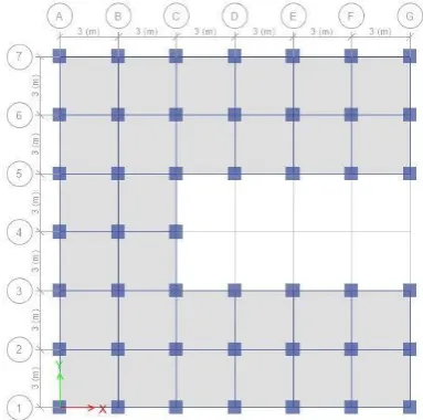
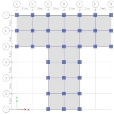
Three irregular structures having plan irregularities. (T L C.) And two systems i.e. moment resisting frame and shear
wall system (dual system) for zone IV are considered. For irregular structural in x-direction there are 6 bays, each of 3
Reinforced concrete walls, which include lift walls or shear walls, are usual requirement of reinforced concrete
multistory buildings. Constructing the shear wall in tall, medium and even short buildings will effect and intern
reinforce the significantly and either more economical than the bending frames. By the shear, we can control the side
bending of structure, much better than other elements like closed frames and certainly the shear walls are more
flexible than them. However, in many occasions the design has to be based on the position of the lift and stair case
walls with respect to the center of mass.
Twisting moments in the members are observed to be having increasing trend with enhancement in the eccentrically
between geometrical centroid of the building and shear wall position. They concluded that shear wall should be placed
at a point by coinciding center of gravity of the building. But the nature of stresses generated in the shear wall
according to its position is also different. The shear wall kept at very near to the center of stiffness act as a vertical
bending element and the shear wall kept at corner of the building are may be compression or in axial tension
according to the direction of the lateral force.
IV. MODELLING DETAILS
Building description
Length x Width 18m x 18m
No. of storey 20
Storey height 3.65
Beam dimensions 500x700
Column dimensions 700x700
Slab thickness 125
Thickness of main wall 230
Height of parapet wall .90
Thickness of parapet wall 115
Support conditions fixed
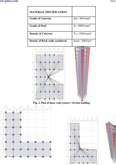
MATERIAL SPECIFICATION
Grade of Concrete fck= 30N/mm2
Grade of Steel fy= 500N/mm3
Density of Concrete ϒc= 25kN/mm3
Density of Brick walls considered brick= 20kN/m3
Fig. 2. Plan of shear wall system C-Section building
V. RESULTS AND DISCUSSIONS
The 3-D models discussed in the above section are modeled in
ETABs software and is analyzed by Response Spectrum Method. The structural responses like lateral
displacements, storey shears, storey drifts are compared and presented.
i. Lateral Displacement in X- direction
The comparative study of Lateral Displacements in structures with increasing Height is shown in graph
below.
20 m height:
a) For C- Section b) For L- Section
c) For T- Section
ii) Maximum storey Forces in X-direction:
a) For C- Section b) For L-
a) For C- Section b) For L- Section
:-c) For T-
Section:-VI. CONCLUSION
On the basis of analysis and results, the following conclusion has been
made:-1) With the introduction of shear wall, storey displacement and storey drift decreases compared to moment
resisting system
2) Storey forces are greater in moment resisting frame than shear wall system by 37 %
3) Time period is also less in shear wall system as compared to moment resistant frame.
4) Response spectrum analysis results provides a more realistic behavior of structure response and hence it can
be seen that the displacement values in both X and Y directions are least in model with shear wall
5) Shear wall system is more economical by 26 % than moment resisting system for given data.
VII. SCOPE FOR FUTURE RESEARCH
The volume of work undertaken in this study is limited to comparison of seismic response parameters in a
building with shear wall in different shapes using linear. The study could be extended by including various other
parameters such as torsional effects and soft storey effects in a building
.Non linear dynamic analysis may be carried out for further study for better and realistic evaluation of structural
response under seismic forces.
REFERENCE
[1.] Himalee Rahangdale , S.R.Satone, Design And Analysis Of Multi Storied Building With Effect Of Shear
Wall, Vol. 3, Issue 3, May-Jun 2013, Pp.223- 232.
[2.] M.Y. Kaltakci, M.H. Arslan And G. Yavuz, Effect Of Internal And External Shear Wall Location On
Strengthening Weak Rc Frames, Sharif University Of Technology, August 2010,Vol. 17, No. 4, Pp.
312-323.
Issue. 4, Jul - Aug. 2013 Pp-2522-2525.
[5.] D. B. Karwar, Dr. R. S. Londhe, Performance Of Rc Framed Structure Using Response Spectra Analysis
International Journal Of Emerging Technology And Advanced Engineering, Volume 4, Issue 6, June
2014.
[6.] Yousuf Dinar, Md. Imam Hossain, Rajib Kumar Biswas, Md. Masud Rana, Descriptive Study Of
Response Spectra Analysis In Rc Structures Of Rigid Joint, Iosr Journal Of Mechanical And Civil
Engineering (Iosr-Jmce), Volume 11, Issue 1 Ver. Ii (Jan. 2014),Pp 60-68.
[7.] Atc-40. “Seismic Evaluation And Retrofit Of Concrete Buildings.” Volume 1 And 2. Applied Technology
Council, California, 1996. [5] Fema-273. “Nehrp Guidelines For The Seismic Rehabilitation Of
Buildings.” Federal Emergency Management Agency, Washington Dc, 1997.
[8.] Fema-356. “Prestandard And Commentary For The Seismic Rehabilitation Of Buildings.” Federal
Emergency Management Agency, Washington Dc, 2000.
[9.] Is: 1893 (Part 1) 2002- Indian Standard- “Criteria For Earthquake Resistant Design Of Structures”, Bureau