A Novel Architecture for a High Performance
Low Complexity Neural Device
Richard P a tric k Palmer
A the si s p r e s e n t e d for a D o c to r of P h il o s o p h y
D e p a r t m e n t of C o m p u te r S c i e n c e
U n i v e r s i t y C o ll eg e , London.
ProQuest Number: 10609310
All rights reserved
INFORMATION TO ALL USERS
The qu ality of this repro d u ctio n is d e p e n d e n t upon the q u ality of the copy subm itted.
In the unlikely e v e n t that the a u th o r did not send a c o m p le te m anuscript and there are missing pages, these will be note d . Also, if m aterial had to be rem oved,
a n o te will in d ica te the deletion.
uest
ProQuest 10609310
Published by ProQuest LLC(2017). C op yrig ht of the Dissertation is held by the Author.
All rights reserved.
This work is protected against unauthorized copying under Title 17, United States C o d e M icroform Edition © ProQuest LLC.
ProQuest LLC.
789 East Eisenhower Parkway P.O. Box 1346
ABSTRACT
This thesis presents a novel architecture on which to implement neural
networks and simple digital signal processing models in a compact and
low cost manner. The need for this architecture was identified from a
particular application; this application requiring a portable real-time
device with which to perform neural network and simple digital signal
processing models on speech signals. The development of the architecture
was driven by this, and other similar applications, and did not start
with any pre-conceived ideas. This allowed complete freedom to be
expressed in its development, enabling a more novel architecture to be
developed.
In this thesis the development of this architecture is reported. This
extends from the analysis of current neural models, the identification
of the necessary features from these, and the creation of a unified
architecture to provide these features. The design of a silicon chip
based on this architecture is then presented.
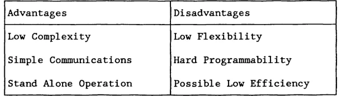
The architecture that has been developed combines the programmability
and high efficiency of MIMD arrays, with the low complexity in both
communications and control of SIMD arrays. The device built using this
architecture incorporates a single processing element that consists of
only 5300 transistors. Projections indicate that a totally integrated
processor array could be built; incorporating fourteen such processors
with on-chip memory, A/D and D/A converters.
An analysis of the architecture, and other architectures that fit into
the same classification class, is then presented. This analysis has been
able to identify some common features with MIMD/SIMD machines, and to
Acknowl e<
I would like to thank many people in helping me during my time working
on this thesis. Mostly I would like to thank Peter Rounce for helping
me during the development of this thesis, and for his tireless reading,
and rereading, of various drafts. I would also like to thank Chris Clack
for volunteering to read this thesis over his Christmas break, and to
Mike Brent for allowing me to use the London VLSI Consortium PAD Frame
utility.
Many thanks also to my parents, flat mates and Simone for putting up
with me during the time spent working on my Ph.D.
Lastly thanks to Steve Wright and the afternoon posse, for keeping a
smile on my face during the many afternoons spent working on this
Contents
Title Page 1
Abstract 2
Acknowledgements 3
Contents 4
List of Figures 9
Chapter 1 Introduction
1.1 The Need for Alternative Computational Methods 12
1.2 Putting Neural Networks to Work 13
1.3 Objectives of this Thesis 14
1.4 Research Contributions 15
1.5 Organisation of Thesis 15
Chapter 2 Neural Networks
2.1 Desirable Features of Neural Networks 18
2.2 Development of Neural Networks 19
2.2.1 Biological Neuron 19
2.2.2 Artificial Neuron 21
2.3 Analysis of Neural Networks 21
2.3.1 Single Layer Network 22
2.3.2 Multilayer Networks 24
2.4 Learning in Neural Networks 26
2.4.1 Unsupervised Learning 26
2.4.2 Supervised Learning 26
2.4.2.1 Single Layer Learning Rule (Delta Rule) 27
2.4.2.2 Multilayer Learning Rule (Backpropagation) 27
2.4.3 Other Learning Techniques 28
2.5 Summary of Neural Networks 29
Chapter 3 Application Areas
3.1 The Development of Speech Processing Systems 30
3.2 Problems to be Addressed 31
3.2.1 Speech Features 31
3.2.2 Phonemes 32
3.3 Difficulties Encountered by Deaf People 33
Richard Palmer Phd.Thesis
3.4.1 The 'Peakpicker' Chip 36
3.4.2 Results Obtained by using SiVo 37
3.4.3 Limitations of SiVo 38
3.5 Neural Networks and Speech Processing 39
3.5.1 Use of Neural Networks at UCL 41
3.5.1.1 Analysis and Resynthesis of Speech 41
3.5.1.2 Fundamental Period Extraction Network 43
3.5.2 Real-Time Implementation for Fx Extraction 45
3.5.3 Requirements for an Alternative Architecture 48
3.6 Conclusion 49
Chapter 4 Architectural Considerations
4.1 The Diversity of Neural Implementations 50
4.1.1 Neural Co-processors 51
4.1.1.1 NETSIM - Texas Instruments 52
4.1.1.2 DELTA Co-Processor - SAIC Corp. 52
4.1.2 Neurocomputers and ASIC Neural Devices 53
4.1.2.1 ETANN - Intel Corporation. 54
4.1.2.2 DNNA - Neural Semiconductor Ltd. 56
4.1.2.3 Intelligent Memory Chips - Oxford Computer 57
4.1.2.4 Hitachi Neural Wafer 59
4.1.2.5 Digital Snake - Univ. Ancona, Italy. 61
4.1.2.5 A Flexible WSI Neural Network - Inst Nat Poly 62
4.2 Assessment of Neural Implementations 64
4.2.1 Analogue Implementations 65
4.2.2 Hybrid and Pulse Neural Implementations 66
4.2.3 Digital Implementations 67
4.2.3.1 MIMD Arrays 67
4.2.3.2 SIMD Arrays 69
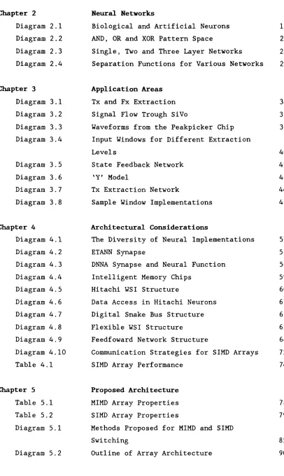
4.3 Analysis of SIMD Arrays 72
4.3.1 Flexibility 73
4.3.2 Performance 73
4.3.3 Real-Time Constraints 75
4.4 Summary of Available Neural Implementations 76
Chapter 5 Proposed Architecture
5.1 Objectives for the Architecture 78
5.2.1 5.2.2 5.3 5.3.1 5.3 5.3 5.3 5.3 5.4 5.4.1 5.5 5.5.1 5.5.2 5.6 5.6.1 5.6 5.6 5.6 5.6 5.6.2 5.6 5.6 5.6 5.6 5.6.3 5.6 5.6 5.6 5.6.4
Chapter 6
6.1
6.2
6.2.1
6.2.2
6.2.3
6.3
6.3.1
rna.xmsls
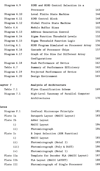
Desirable Feature of MIMD Arrays gQ
Desirable Feature of SIMD Arrays g-^
How to Combine these Features g2
Combining MIMD and SIMD Control 22
1.1 Storage of MIMD and SIMD Control Strategies 83
1.2 Control Switching & Virtual Neuron Definition 83
1.3 Proposed Communications Scheme g-j
1.4 Synchronisation of Processors gg
Proposed Architecture gg
Architecture of Processing Element g-^
Programming Strategy gg
SIMD Program ^
MIMD Program ^
Application Notes and Examples ^y
Programming Techniques jy
1.1 Definition of Virtual Neuron
1.2 Initialisation and Synchronisation k i
1.3 Implementation of Input Window K 2
1.4 Communication of Partial Sums 1(4
Application Examples k &
,2.1 Fully Connected Network K g
,2.2 State Feedback Network K g
,2.3 Finite Impulse Response Filter K g
2.4 Infinite Impulse Response Filter 1]q
Tx Extraction Implementation 121
3.1 Silicon Efficiency 122
.3.2 Reduced Sample Period I23
3.3 Reduced Response Time IK
Summary of Implementation Examples I K
Detailed Description of Design
Design of CMOS Implementation IK
Algorithms used for the Arithmetic Fuic^ions 1 1;
Pointer Manipulations H,
Partial Sum Additions I K
Multiplication Instructions 1 2(
Datapath Construction 1 2'
Kicnara maimer Pha.Thesis
6.3.2 Arithmetic Unit 125
6.3.3 Saturated Addition 126
6.3.4 Double Length Shift 128
6.3.5 Execution of a Single Multiply Iteration 129
6.3.6 Simulation of Datapath 130
6.3.7 Datapath Performance 133
6.4 Generation of Instruction Decoder 134
6.4.1 PLA Template 135
6.4.2 PLA Personality Matrix 136
6.5 Development of Control Switching 137
6.5.1 Transition from MIMD to SIMD 140
6.5.2 Transition from SIMD to MIMD 141
6.5.3 Implementation of Control Switching 144
6 . 6 Development of SIMD Control 147
6.7 Implementation of Bus Logic Functions 150
6.7.1 Modulo Address Generation 150
6.7.2 Sigma Table Bus 152
6 . 8 Full Simulation of Processor Array 155
6.9 Design Conclusion 155
6.10 Future Large-Scale Integration 158
6.11 Design Environment 164
Chapter 7 Analysis of Architecture
7.1 Classification of Parallel Machines 169
7.2 Other MIMD/SIMD Machines 172
7.2.1 Non-Von 4 - Columbia University 172
7.2.2 DADO - Columbia University 173
7.2.3 XIMD - Carnegie Mellon University 174
7.3 MIMD/SIMD Machines in the Future 175
7.4 Postscript 177
Chapter 8 Conclusion
8.1 Summary of Thesis 178
8.2 Research Contribution 178
8.3 Literature Published 180
Plates
Richard Palner Phd.Thesis
P.2 Operation of a Confocal Light Microscope 181
Appendix
1 LOCAL Finite State Machine 190
2 GLOBAL Finite State Machine 195
3 Instruction Decoder 200
4 Netlist Generation 214
i) NET 215
ii) LABELS 216
iii) NETLIST 217
5 ESP Program Listing 220
6 PAD Frame Request File 223
7 Performance Analysis 227
8 Literature Published 231
i) R. Matthews 232
ii) P Write 233
iii) R. Palmer 234
L i s t o f F i g t a r e s
Chapter 2 Neural Networks
Diagram 2.1 Biological and Artificial Neurons 19
Diagram 2.2 AND, OR and XOR Pattern Space 22
Diagram 2.3 Single, Two and Three Layer Networks 24
Diagram 2.4 Separation Functions for Various Networks 25
Chapter 3 Application Areas
Diagram 3.1 Tx and Fx Extraction 34
Diagram 3.2 Signal Flow Trough SiVo 35
Diagram 3.3 Waveforms from the Peakpicker Chip 37
Diagram 3.4 Input Windows for Different Extraction
Levels 40
Diagram 3.5 State Feedback Network 41
Diagram 3.6 'Y' Model 42
Diagram 3.7 Tx Extraction Network 44
Diagram 3.8 Sample Window Implementations 47
Chapter 4 Architectural Considerations
Diagram 4.1 The Diversity of Neural Implementations 51
Diagram 4.2 ETANN Synapse 55
Diagram 4.3 DNNA Synapse and Neural Function 56
Diagram 4.4 Intelligent Memory Chips 59
Diagram 4.5 Hitachi WSI Structure 60
Diagram 4.6 Data Access in Hitachi Neurons 61
Diagram 4.7 Digital Snake Bus Structure 62
Diagram 4.8 Flexible WSI Structure 63
Diagram 4.9 Feedfoward Network Structure 64
Diagram 4.10 Communication Strategies for SIMD Arrays 72
Table 4.1 SIMD Array Performance 74
Chapter 5 Proposed Architecture
Table 5.1 MIMD Array Properties 78
Table 5.2 SIMD Array Properties 79
Diagram 5.1 Methods Proposed for MIMD and SIMD
Switching 85
Richard Palmer Phd.Thesis
Diagram 5.3 Overview of Processor Architecture 92
Listing 5.1 SIMD Synapse Update Program 94
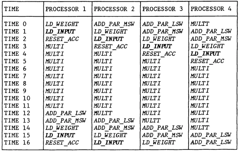
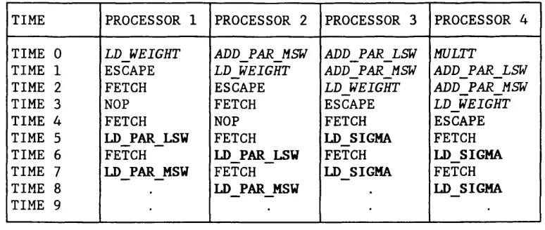
Table 5.3 Execution of SIMD Program Across Array 95
Listing 5.2 Virtual Neuron Definition 98
Table 5.4 Arbitration of LD_SIGMA Instructions 99
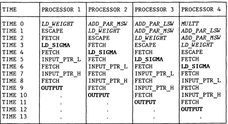
Table 5.5 Execution of SIMD Program Across an Array 100
Listing 5.3 Initialisation and Synchronisation 101
Diagram 5.3 Input Window Implementation 102
Listing 5.4 Input Window Implementation 104
Listing 5.5 Partial Sum Communications 105
Table 5.6 Synchronisation of Processors 106
Diagram 5.4 Fully Connected Network 107
Listing 5. 6 Fully Connected Network 107
Diagram 5.5 State Feedback Network 108
Listing 5.7 State Feedback Network 109
Diagram 5.6 Finite Impulse Response Filter 110
Listing 5.8 Finite Impulse Response Filter 110
Listing 5.9 Infinite Impulse Response Filter 111
Diagram 5.7 Infinite Impulse Response Filter 112
Table 5.7 Silicon Efficient 113
Table 5.8 Reduced Sample Period 113
Table 5.9 Reduced Response Time 114
Table 5.9 Summary of Solutions 115
Chapter 6 Detail Description of Design
Table 6.1 Multiplication Shift Modes 123
Diagram 6.1 Datapath Schematic 124
Diagram 6.2 Clocking Strategy 126
Table 6.2 Adder Input Selection 126
Diagram 6.3 Arithmetic Unit 127
Table 6.3 Saturated Addition Control 127
Diagram 6.4 Saturated Addition Logic 128
Diagram 6.5 Double Length Shift 129
Diagram 6 . 6 Multiplication Flow for $1 131
Diagram 6.7 Multiplication Flow for $2 132
Table 6.4 MIMD Two Stage Pipeline 138
Table 6.5 SIMD Three Stage Pipeline 139
Kicnara raimer rna.inesis
Diagram 6.9 SIMD and MIMD Control Selection in a
Processor 145
Diagram 6.10 Local Finite State Machine 146
Diagram 6.11 SIMD Control Block 148
Diagram 6.12 Global Finite State Machine 149
Table 6 . 6 Modulo Buffer Sizes 151
Diagram 6.13 Address Generation Control 151
Diagram 6.14 Sigma Function Threshold Levels 152
Diagram 6.15 Sigma Threshold Function Logic 154
Listing 6.1 MIMD Program Simulated on Processor Array 156
Diagram 6.16 Cascade of Processor Chips 157
Diagram 6.17 Graph of Die Size for Different Array
Configurations 160
Diagram 6.18 Peak Performance of Device 162
Table 6.7 Summary of Performance Efficiency 162
Diagram 6.19 Projected Performance of Device 163
Diagram 6.20 Design Environment 165
Chapter 7
Table 7.1
Diagram 7.1
Analysis of Architecture
Flynn Classification Scheme 169
High-Level Taxonomy of Parallel Computer
Architectures 170
Plates
Diagram P.l Confocal Microscope Principle 181
Plate la Datapath Layout (MAGIC Layout) 183
Plate lb Adder Layout
i) MAGIC Layout 184
ii) Photomicrograph 184
Plate Ic B Input Selection (XOR Function)
i) MAGIC Layout 185
ii) Photomicrograph (Metal 2) 185
iii) Photomicrograph (Poly & Diff) 186
iv) Photomicrograph (Metal 1) 186
Plate Ila Template for Decoder PLA (MAGIC Layout) 187
Plate lib PLA Layout (MAGIC LAYOUT) 188
Chapter 1
t i on
This chapter presents the main motivating factors for research into
neural networks, and looks at how neural networks are being introduced
into real applications. An overview of this thesis is then given, which
includes a breakdown of the contents of each chapter.
Ever since Von Neumann in the 1940s, computers have been developed using
similar methods. The two key points that Von Neumann introduced were:
Today's technology has allowed the computational power of these machines
to be fully realised, with increasingly powerful processors being
regularly introduced.
Compilers and high-level languages are also developing, further
simplifying the task of program writing and allowing increasingly
complex problems to be solved. Advances in expert systems have further
simplified this task by allowing computers to be programmed by sets of
rules. These rules can be generated by an expert in the relevant field
without requiring any knowledge about programming.
Despite these advances the two main features of Von Neumann machines
remain, and these features now pose limitations to some of the problems
that computers are attempting to solve.
•Internal Program
The requirement of a program involves the development of an
algorithm, or set of rules, that very precisely define the
operations required. This can present major problems in many tasks
such as pattern recognition, signal processing and optimisation,
1.1 The Need for Alternative Computational Methods
•Internal Program
Richard Palmer Phd Thesis
where algorithms are difficult to determine due to the imprecise
nature or knowledge of the task.
•Serial Operation
The requirement of serial operation, although slightly relaxed in
array and pipeline processors, has limited the performance of
computers. Only small sections of hardware can be kept active at
any one moment, so limiting the performance that could be obtained
with today's large scale integration.
The development of neural networks has been inspired by these drawbacks
in conventional computing, and by the way that biological systems
process information. Neural networks try to capture the processing
techniques used by these biological systems, and to exploit their
benefits:
•Learning
By using learning rules inspired by biological systems, computers
can be made that adapt to their environment, and learn specialised
functions. This operation requires no programming, but instead a
series of examples are presented along with examples of the
required response. This eliminates the requirement for algorithms
to be devised before a problem can be solved.
•Parallel Operation
The algorithms used in neural networks are naturally parallel, and
rely upon localised communications. This allows arrays of
processors to be built with an almost limitless expandability,
thus making much better use of the processing power that can be
obtained from large scale integrated circuits.
1.2 Putting Neural Networks to Work
Neural networks have been the subject for research since the 1940s,
although most of the major breakthroughs have been more recent. In the
last few years neural networks have begun to emerge from the research
Richard Palmer Phd Thesis
The first commercial systems to make use of neural networks were
software packages to run on conventional hardware. One such system was
the NESTOR Development S y s t e m m . An early project tackled by the NESTOR
Development System was bond-trading predictions; a network was taught
on recent transactions and their outcomes, and it quickly learnt to
replicate these transactions, and even improved upon then.
To enable neural networks to further increase their usefulness required
specialised hardware to speed the computations of these networks. SAIC
(Science Applications International Corporation) was one of the first
sources of specialised hardware on which neural networks could be
implemented. SAIC developed several products built around the DELTA
processort2]; these act as co-processors to a conventional host computer,
or work in a stand-alone environment.
This increased processing power means that neural networks no longer
have to run off-line with pre-prepared data, but instead they can work
with fast incoming data in real-time systems. An example of this is the
TNA explosive detection system[3]. This system is now being installed at
major airports to monitor luggage for explosives. Neural networks are
used to perform an analysis on the absorption spectrum of low energy
neutrons, from which many different types of explosives can be detected.
1.3 Objectives for This Thesis
The need for still faster hardware, and for a larger network capacity,
has continued. To address this problem many ASIC (Application Specific
Integrated Circuit) designs have been proposed and built. A common aim
in these designs has been to exploit the natural parallelism, and
localised communications found in neural networks. This has enabled
neurocomputers to be developed with an almost limitless expandability.
The digital architectures that have been developed fall into two
classes: fine grained SIMD (Single Instruction Multiple Data) arrays,
and coarse grained MIMD (Multiple Instruction Multiple Data) arrays.
SIMD machines tend to show low flexibility, and can also have problems
Richard Palmer Phd Thesis
optimally to the array.
MIMD machines offer increased flexibility, and can achieve close to
linear speed up with increased numbers of processors. However MIMD
arrays achieve these characteristics by the use of complex
communications and control mechanisms, adding considerably to the
hardware requirements for such a machine.
This thesis highlights these problems, and proposes an alternative. The
solution proposed brings together features from SIMD and MIMD arrays,
and develops a unified architecture on which to exploit the benefits
from each. This architecture is examined in detail, including both its
programming, and the design of a CMOS device built implementing it.
1.4 Research Contributions
The main research contributions of this thesis have made to the area of
neural architectures and parallel computing. To list the key features
that have been presented would include:
• Critical study of the current state in neural implementations
•Development of an hypothesis out of which a new architecture
could be developed
•Development of a software methodology combining SIMD and MIMD
control
•Development of an architecture to support this software
methodology
•Design of a silicon chip incorporating this architecture
•The identification of other similar work
1.5 Organisation of Thesis
Richard Palmer Phd Thesis
which is shown below.
Chapter 2 Neural Networks
This chapter looks at biological neurons and artificial neural networks.
It covers the development of the multilayer perceptron model, with
particular emphasis on the pattern recognition ability of different
network topologies. Simple learning rules are then presented, with
emphasis on the problems encountered by these algorithms.
Chapter 3 Application Areas
This chapter looks at an application area to which neural networks have
been applied. One specific application is chosen, with the various
techniques that have been used in its development being evaluated. This
highlights the problems that were encountered, and shows how neural
networks were used in solving them.
The problem that remains for this application was how to efficiently
implement the neural model that was developed; this problem is further
complicated since the proposed use for this network is in a portable
real-time device. The problems involved in this implementation are
highlighted, and are used as the design criteria for the architecture
that has been developed.
Chapter 4 Architectural Considerations
In this chapter a survey of the current neural architectures is carried
out. This survey takes a few specific examples, each chosen since it
highlights a particular technique that is used to implement neural
networks. From the analysis of these examples it was possible to
identify features from various architectures that would be beneficial
for the architecture being developed. An hypothesis is proposed at the
end of this chapter: this states that if the beneficial properties of
both MIMD and SIMD arrays could be combined in a unified architecture,
this would result in suitable architecture for the application given in
Richard Palmer Phd Thesis
Chapter 5 Proposed Architecture
This chapter covers the development of an architecture to test the
hypothesis presented in the previous chapter. This covers some of the
deign decisions that were made, and presents the overall architecture
for an array and an individual processor. Programming and application
examples are then given, these illustrate the flexibility of the
architecture, and give some ideas as to how it can be programmed.
Chapter 6 Detailed Description of Design
This chapter outlines an implementation using the presented
architecture. Major emphasis in this chapter is put upon how both MIMD
and SIMD control strategies are used, and how switching between them is
performed.
Future work is also covered in this chapter; this investigates the
possible development of a fully integrated neural signal processor. This
device would operate in a stand-alone environment, with memory, A/D and
D/A converters being held on-chip.
Chapter 7 Assessment of Architecture
After presenting an implementation using this architecture, a more
general look at the architecture is made. This chapter first classifies
this architecture in a number of ways, and then look at other
architectures that are similar. This chapter concludes with the possible
direction in which this class of architecture might lead.
Chapter 8 Conclusion
This chapter summarises the key points presented in this thesis, and
highlights the main research contribution that have been made. A list
of publications is given, including those which the author is hoping to
Cliapter 2’
Neural Networks
Neural networks are biologically inspired forms of computation, that
represent a departure from conventional forms of computing. Neural
processing involves the use of very simple computational units that are
highly interconnected and work in parallel.
The human brain is composed of 10u neurons connected by 1015 interconnec
tions. The brain is made up of 99% interconnections, with only 1%
computational units, and works in an analogue manner. The brain is
believed to be purely asynchronous with no central control unit. There
is instead an homologous distribution of information, thought to be
almost entirely held in the interconnections.
2.1 Desirable Features of Neural Networks
Neural networks try to capture a number of features from the brain in
order to provide artificial processing systems that exhibit marked
differences from conventional computer systems. The main properties that
are sought for these artificial processing systems are:
•Learning
Learning is probably the most important feature that the brain
exhibits. It allows an individual to experiment with the environ
ment, and using feedback, to modify its behaviour. This process
is very complex in the human brain, with both short and long term
memories playing important roles. Simplifications of these
learning methods can allow learning to be incorporated into neural
networks.
•Generalisation
Generalisation allows a system to respond to uncertain data in a
predictable manner. It involves using past knowledge to formulate
the best response to a new situation or uncertain data. It is
Richard Palmer P h d .Thesis
uncertain data that computers find extremely difficult. Simple examples of such a task would include speech and visual recogni tion.
•Redundancy
Redundancy enables a system to continue functioning, even when parts are damaged. This feature can also be called graceful degradation, as it ensures a slow reduction in the performance as more parts become damaged. This property would be beneficial for computer systems, where at present a single defect can be disastrous.
2.2 Development of Neural Networks
An artificial neuron is a mathematical entity that was developed by McCulloch and Pitts 1 9 4 3 m , Hebb 1949[2] and Rosenblatt 1959[3], to model the functioning of a biological neuron. Diagram 2.1 shows the structure of a biological neuron and its artificial counterpart.
\ \ S y n a p s 6
C e n B o d y
D e n d r i t e
--I n p u t 1 ____W e i g h t t
input 2 n ' - N 0 u t p u |
i n p u t n w e i g n t n
/ n \
/ m n \
O u t p u t = p n (
y
I n p u t , We i g n r , t\ 1= 1 /
a) B i o i o Q' o a ' N e u r o n c) A r t i f i c i a l Ne u r o n
Diagram 2.1 Biological and Artificial Neurons
2.2.1 Biological Neuron
Kicnara raimer rna.inesis
At the end of each axon lie the dendrites; these fan-out allowing each
neuron to transmit its output to many other neurons. The mass
connectivity obtained from these dendrites is seen to be crucial to the
functioning of the brain.
Each neuron has many thousand inputs, coming from the dendrites of other
neurons, or from sensory organs. These inputs are called synapses, and
consist of a 20-30nm gap between the incoming nerve terminal and the
input receptor on the cell body of the neuron. It is through the
synapses that the incoming information is processed.
Nerve signals are transmitted as variable frequency pulses through the
axon. These are integrated by the nerve ending, resulting in a variable
quantity of 'Neurotransmitter' being released across the synapse. This
neurotransmitter is picked up by the input receptor on the cell body,
and results in a change in the membrane potential at that point on the
cell membrane. This change can occur in two ways, either as an increase
in membrane potential, excitatory, or as a decrease in membrane
potential, inhibitory. The combined effect of the many thousands of
input receptors results in overall changes to the cell membrane
potential.
At equilibrium a potential exists across this cell membrane, which is
the result of charged ions flowing through the membrane. Due to the
membrane having varying permeability to the different ions this
potential is about -60mV at equilibrium. This is called the resting
potential.
The effect of the different neurotransmitters results in the membrane
potential varying across the cell body. The amount of change in this
membrane potential is dependent upon the strengths of the excitatory and
inhibitory incoming impulses, and their locality.
If at any point on the cell body the membrane potential changes by as
much as +20mV, a change occurs in the structure of the membrane. This
action is called depolarisation, and effects the membrane by suddenly
allowing certain ions to pass more freely. This sudden movement of ions
Kicnara t'aimer rna.inesis
depolarising the surrounding area. The outcome of this is an impulse
that spreads across the cell membrane, and down the axon. This impulse
is then transmitted along the axon to the dendrites, resulting in this
signal being transferred to further neurons. After each impulse has
passed the resting potential is quickly reinstated, and this whole
action can then be repeated.
Although the impulses transmitted down each axon are of fixed amplitude,
and vary only in frequency, the operation of the biological neuron is
fundamentally analogue. The cell bodies main processing task being the
temporal and spatial summation of the input pulses across the cell body.
2.2.2 Artificial Neuron
The important features of the above description have been used to
formulate the model most widely used for the artificial neuron.
Structurally the artificial neuron can be made to look very similar,
with several inputs, a neural function and an output that feeds to many
other neurons. The mathematical function of an artificial neuron is
shown in Diagram 2.1.b. and consists of applying a function to the
weighted sum of each input.
The function most commonly used is a sigma function, since this solves
many problems encountered by early research. It allows small signals to
pass reasonably unaffected, while stopping large signals saturating the
neuron's output. This is especially important in multilayer networks,
where the outputs from one layer provide the inputs to the next.
This very simplistic model of a biological neuron does not attempt to
imitate every feature. However it does mimic very well the important
feature of mass connectivity, and distributed processing found in
biological systems.
2.3 Analysis of Neural Networks
The following sections looks at the properties of various network types,
Kichara Falmer r h d . inesis
2.3.1 Single Layer Network
The simplest network that can be used is a single layer of neurons. This type of network was widely researched by the developers of the artificial neuron, and simple learning rules were developed. The Delta Rule was developed by Rosenblatt in 1959[3] and is the most common.
After extensive research into this class of network it was shown by Minsky and Papert in 1960[4] , that these networks lacked any real power in pattern recognition. The problem used to show this was the XOR, or parity problem. This problem is discussed below - in this example a single neuron is used for the analysis. Minsky and Papert were able to extend this simple analysis onto any single layer network, and hence showed the fundamental limitations of this type of network.
Diagram 2.2 AND, OR and XOR Pattern Space
The XOR Problem
By taking a single neuron with two inputs (A & B) there are 4 possible binary patterns that can be represented. These can be plotted in a two
dimensional pattern space, with the four input patterns being
represented by the corners of a square. Several functions can be
performed on these input patterns: these are the Boolean logic
Richard Palmer Phd.Thesis
Minsky and Papert used a series of simple equations to show the possible
separations that a single layer network could perform. The first two
Boolean functions can be easily expressed by using the following
equations, where:
Wa = Weight for Input A Wb = Weight for Input B
Neural Function is a Threshold at 0.5
AND
OWa + OWb < .5 OWa + lWb < .5 lWa + OWb < .5 lWa + lWb > .5
Solution: .25 < Wa < .5
.25 < Wb < .5
OR
OWa + OWb < .5 OWa + lWb > .5 lWa + OWb > .5 lWa + lWb > .5
Solution: Wa > .5
Wb > .5
However the third function, XOR, cannot be expressed so easily. The four
equations below describe the line used to determine the XOR pattern
space. These four equations are clearly inconsistent.
XOR
OWa + OWb < .5 OWa + lWb > .5 lWa + OWb > .5 lWa + lWb < .5
This example shows the limitations of a single neuron. The only pattern
recognition functions that can be performed by a single neuron are those
that can be separated by a single line. This class of functions is
Kicnard Palmer Phd.Thesis
Linear separability can be extended into many dimensions, with
hyperplanes being used instead of linear lines to determine the separation. Minsky and Papert showed that although many neurons can be used in a single layer network, only linear^separable functions can be expressed.
2.3.2 Multilayer Networks
Minsky and Papert concluded that the only useful class of neural networks were those that incorporated two or more layers, this class is known as multilayer networks.
However the problem that remained was in teaching these multilayer networks. Unless the weights can be taught, the complex patterns that these networks can represent can never be realised. It was this problem of teaching multilayer networks that caused the research in neural
networks to die back. It was not until 1986 when Rumelhart and
McClelland[5] developed a learning rule for multilayer networks, that research expanded and developed rapidly.
Diagram 2.3 shows a single layer, two layer and a three layer network. The connectivity between the layers in multilayer networks is normally 100%, that is each neuron is connected to every neuron in the preceding layer (fan in), and is also connected to every neuron in the following layer (fan out). The layers are conventionally labelled as:
O u t p u t s I n p u t s
I n p u t s O u t p u t s O u t p u t s
H i d d e n O u t p
Layer Laye L a y e r
P) I w o La y er N e t w o r k
K.jLciiiiLu raimer m u . xuui»it>
•Input Layer
This layer does no processing, and is only used to represent the number of inputs to the network.
•Hidden Layers
The layers inside the network are labelled hidden layers, due to their outputs being hidden. If there is more than one hidden layer then they are numbered, starting with the layer nearest the input l ayer.
•Output Layer
This layer provides processing, and represents the output from a network. In a single layer network the output layer represents the only processing layer in the network.
The power that multilayer networks provide depends upon the number of layers in the network. The addition of each layer can be likened to ability of drawing more separation lines in the pattern space. Diagram 2.4 shows the possible separations with single layer networks, two layer networks and three layer networks, each with reference to a two-input network.
t,Q
o.o B
b) Two Layer N e t w o r k
Richard Palmer Phd.Thesis
2.4 Learning in Neural Networks
There are two basic classes of learning algorithm used in neural
networks: unsupervised and supervised learning.
2.4.1 Unsupervised Learning
In unsupervised learning the network is encouraged to experiment, and
to discover for itself the required response. This form of learning is
particularly suitable for cases where no model answers are available,
since the network will determine its own set of rules to suit the
application.
To teach the network it has to be presented with an input set of
conditions. At the start of learning the network produces a random
response, this is judged according to the suitability of this response.
The score produced helps the network to determine whether the response
was good or bad. Learning is then carried out by either adjusting the
connections to increase this response on a good score, or to decrease
the response on a bad score. By repeating this a series of times
acceptable performance may be achieved, and the network can be put to
work.
While the network is being used the connections can either be frozen to
stop future learning, or learning can be allowed to continue. This
continuation of learning can be beneficial as it allows the network to
adjust to changes in the environment.
2.4.2 Supervised Learning
In this form of learning a network is provided with an input set of
conditions, and is shown the required response to this input set. By
examining the difference between the network's output and the required
response, a set of error values can be calculated. The network then
modifies its connections to minimise these error values. By repeating
this process through many input and output pairs a network will be
Kicnard. Palmer Pnd.Thesis
The following algorithms have been developed for supervised learning in
single and multilayer networks.
2.4.2.1 Single Layer Learning Rule (Delta Rule)
The teaching of a single layer network is fairly simple, since each
neuron's error can be directly calculated. Learning is done by repeating
the following two stage procedure until an acceptable performance is
obtained.
•Forward Stage
The forward stage involves presenting an input set to the network,
and allowing the network to iterate. It is this phase of the
network that is used in recognition mode when learning is
complete.
•Reverse Stage
During the reverse stage the weights are altered so that the
network output will better match the required output set. A S
value is calculated for each neuron by taking the product of the
error and a derivative of the sigma function. Each weight for that
neuron is then updated by adding the product of the neuron's 6
term and each input value to the relevant weight.
2.4.2.2 Multilayer Learning Rule (Backpropagation)
This learning rule is an extension of the Delta Rule and is used in
multilayer networks. As stated above the main problem encountered in
teaching multilayer networks is in generating error terms for the hidden
units. This is obtained by the following procedure:
•Forward Stage
The forward stage involves presenting an input set to the network,
and allowing the network to iterate. It is this phase of the
network that is used in recognition mode when learning is
Kichard Calmer rna.inesis
•Reverse Stage
This reverse stage is executed one layer at a time, taking the
output layer first. The same operation is carried as in the Delta
Rule to calculate a 8 term for each neuron in the output layer,
and to adjust the weights in this layer.
To continue this operation for the hidden layers requires the
generation of the error terms for each hidden layer neuron. This
is achieved by using the 8 terms calculated in the output layer,
and backpropagating these to the preceding hidden layer. In this
operation the weights in the output layer work in reverse.
Summation is then performed on all backpropagated errors in each
hidden layer neuron, providing an error term for that neuron. Each
weight is then modified by taking this error term and using the
Delta Rule in the normal manner.
Many hidden layers can be trained using this algorithm. By repeating
this operation back through the layers, error terms can be derived for
every neuron.
2.4.3 Other Learning Techniques
There are other features that have been introduced to improve the speed
and efficiency of learning. These are as summarised below:
•Training Constant
A training constant can be used to modify the speed of learning.
This is a value (typically 0.1 to 1.0) that is multiplied with the
8 term before modifying the weights, hence varying the rate at
which the network learns. This value can be continuously changed
during learning to optimise the rate of learning.
•Neuron Bias
To speed the convergence of a network it can be beneficial to add
a bias to each neuron. This bias shifts the sigma function to
increase the gain where it is most needed. To calculate this
offset an additional input is made to each neuron: this is fixed
Richard Palmer Phd.Thesis
on this input in the normal manner. After learning this weights
value is used as the neuron's bias, and is added to the partial
sum for each iteration.
•Momentum
This is another method used to speed up the learning in
multilayered networks. By adding a momentum value to the offset
of each weight it is possible to speed the convergence for the
network. This momentum value is determined by taking the last
weight offset and multiplying it by some factor.
2.5 Summary of Neural Networks
This chapter has outlined some of the problems and techniques
encountered in single layer and multilayer networks. The capabilities
of these networks are extensive, with theoretical studies showing very
high performance in pattern recognition. However, as previously
mentioned, the real power of networks can only be realised by the
teaching of these networks to represent complex pattern spaces. It is
this task of teaching networks that present one of the major challenges
Chapter 3
Application Areas
The application areas for neural networks are extensiveti]. A list of
just a few successful examples would include optimisation, forecasting,
control, and signal processing. To obtain a greater knowledge of how
neural networks are being used, and the work involved in developing
working neural systems, this chapter takes one specific application.
The application chosen is taken from work that has been carried out by
the Phonetics Department at University College, London.
This chapter shows the alternative methods that have been used in
developing a speech processor that can be used to simplify a speech
signal, and then to re-present it in this simplified manner to a deaf
person. The discussion covers the traditional methods that have been
used in solving this problem, and presents a neural network solution
that has been developed. The neural network developed for this
application provides a more robust and elegant solution than the
alternative techniques that had previously been used.
This chapter finishes with a discussion on a real-time implementation
that had been built to execute this neural network. This implementation
highlights the problems that exist in developing real-time neural
systems, with particular reference to the small size, and portability
requirements of this application. This chapter concludes with some
requirements that I have isolated for an architecture that would provide
an alternative, and possibly better implementation for this class of
problem.
3.1 The Development of Speech Processing Systems
A group of about 10 members from the Phonetics Department at University
College London, Guys Hospital and Cambridge University have joined
together to research in the same area. They have formed what they call
the EPI (External Pattern Input) Group. The objective of this group is
Richard Palmer Phd.Thesis
that it is possible to represent speech as several separable patterns.
Their aim is to extract these basic patterns, and to reconstitute them
in a form suitable for those people who find difficulty in understanding
normal speech. This project is aimed at profoundly deaf people, and even
the totally deaf. Work has been done to provide the totally deaf with
electrical implants, which give an electrical stimulus to the auditory
nerve, resulting in some sensation of hearing.
Both the profoundly deaf, and the totally deaf with electrical implants,
suffer from the same problems when attempting to understand speech. The
cause of this is that their hearing can only occur in a small frequency
band, usually at the lower end of the audio frequency range. The
frequency analysis carried out by the ear also becomes less accurate,
making it difficult to distinguish between similar frequencies. These
hearing problems result in these people being able to hear noises, but
not with a wide enough spectrum to understand speech fully.
The objective for the EPI group is to develop a system that can identify
various speech patterns, and then re-present these to the deaf person,
using only the limited frequency ranges available and in a much
simplified form.
3.2 Problems to be Addressed
Before examining the project in detail we must first study the basic
properties of speech. Since speech exhibits a highly complex arrangement
of signals, a hierarchy is used in its analysis. This helps to classify
the signals, and to provide a uniform representation.
This hierarchy consists of three levels:
Speech Features
Phonemes
Words and Sentences
3.2.1 Speech Features
Richard Palmer Phd.Thesis
can be attributed to the differing methods used in their production.
They do not have clear cut properties, and differ between different
speakers. Pitch variation, relative power and time duration all modify
these features slightly. The three main speech features are:
•Frication
Frication is produced by passing air over the tongue and lips.
This produces the high frequencies as used in /s/ and /z/.
•Voicing
Voicing is produced by the vocal cords, which provides a full
spectrum of excitation. This is then subjected to selective
filtering as it passes up through the vocal chambers, producing
a wide variation of sounds. For each sound the excitation is the
same, it is the shape of the throat and the mouth which causes
the variations to the sounds. The voicing feature is used to
produce all the vowels.
•Nasal
Nasal sound is produced by vocal cord excitation, and the forcing
of this through the nasal passage and out through the nose. This
can be done either by pressing the tongue to the roof of the
mouth, or by closing the lips. The sounds with the nasal feature
are /n/ and /m/. Variations to these sounds are caused by the
shape of the nasal passage, and tend to be higher in pitch than
vocal sounds, due to the smaller size of the nasal chambers.
3.2.2 Phonemes
Speech features are combined to produce the next level in the speech
hierarchy. This hierarchical level is represented by phonemes.
When attempting to recognise phonemes several problems occur; the same
phoneme can sound very different depending upon its context, and they
exhibit wide speaker-to-speaker variations. The effect of the context
on the sound of a phoneme is due to neighbouring phonemes 'blurring'
together; this is called coarticulation. Coarticulation occurs between
Kicnara rainier Phd.lhesis
major problems when attempting to recognise speech: word boundaries
become difficult to pinpoint, and the same word will sound different
depending on the preceding and following words.
These problems combine to make speech recognition a highly complex task.
Very subtle distinctions separate similar sounding words, with the whole
meaning of the speech relying upon fine discriminations between these
patterns.
3.3 Difficulties Encountered by Deaf People
To help understand speech, it is useful to distinguish the relative
strengths of each of these features. A high level of separation is
required as many sounds may differ in just one speech feature. For
example the difference between /p/ and /b/ is made only by the presence
or absence of voicing: voicing being present in /b/ and not in /p/.
The voicing feature had been concentrated on first by the EPI Group.
This had been decided because voicing is almost invisible to a
lipreader, as all the movements are carried with in the throat. The
voicing feature is also very useful since it provides information about
timing and stress, and it can be used as feedback to the deaf person
while he or she is speaking.
3.4 First Generation of Devices - SiVo
From their analysis of these problems the EPI Group were able to develop
their first generation of aids; Microstim and SiVo (Sinusoidal Voice
Aid) [2,3], These are very similar in design: Microstim was designed for
totally deaf, while SiVo was for the partially deaf. SiVo is described
below; what is said applies just as well to Microstim.
The basic aim of SiVo is to extract the peaks from the voiced
fundamental frequency, and to construct a sine wave to represent this
information. This sine wave is constructed so that its frequency maps
that of the fundamental frequency peaks, giving the patient a
Richard Palmer Phd.Thesis
a TJ3
SPEECH WAVEFORM
a £
<
VOICE FUNDAMENTAL PERIOD (TX)
VOICE FUNDAMENTAL FREQUENCY(Fx)
SiVo OUTPUT
Diagram 3.1 TX and FX Extraction
Diagram 3.1 shows the abstraction of speech, first to provide the
fundamental period (Tx), and then the fundamental frequency (Fx).
Finally the sinusoidal output is provided, with its peaks corresponding
with those of the original voice waveform, and the Tx instances.
SiVo operates by picking out the peaks in the audio waveform, which are
used to represent the voiced fundamental period (Tx). This peak picking
is done by a threshold function on the speech waveform. Diagram 3.2
shows the signal flow through the various stages of SiVo.
The speech signal is first preprocessed to filter out the higher
frequencies in the waveform; this has the effect of removing the
background noise and the unwanted voiceless speech sounds.
The peaks that are extracted are then digitally processed to estimate
the voiced fundamental frequency (Fx). An optional frequency mapping can
be applied to give either a 50 Hz or an 80 Hz frequency drop, this
feature is selected by the 'MAPITCH' switch. This MAPITCH switch ensures
that the output from the device falls within the audio frequency range
of the listener.
The amplitude of the required sine wave is calculated by use of a lookup
table, this ensures that a comfortable listening volume is achieved at
all frequencies that the device can offer (31 Hz to 707 Hz). The
amplitude lookup is necessary since different patients have different
Richard Palmer P h d .Thesis
GENERATE O U T P U T SINE WAV E
E A R PH O N E M IC RO PH ON E
V O LU M E CONTROL S E N S IT IV IT Y
C O N T R O L
MAPITCH SWITCH
A M P L IF IE R LOW PASS FILTER
LOOK UP O U T P U T A M P L IT U D E APPLY FREQ
M A P P IN G EX T R A C T VOICE
FUNDAMENTAL FREQ.
Diagram 3.2 Signal Flow Through SiVo
provided, considerable discomfort would be experienced in some frequency bands where the patient may have good hearing, and no hearing may be present in particularly bad frequency bands. The resultant waveform is generated in an analogue fashion, and presented to the patient via an earphone.
The difference between SiVo and Microstim devices is only in the resultant waveform. A square wave is produced in Microstim, which is applied, via an ear moulded electrode, directly to the inner ear.
The first implementation of SiVo uses a mixture of analogue and digital techniques. The preprocessing and the threshold function is carried out by analogue techniques, while the actual sinusoidal output is produced by a microprocessor and a D-A converter. The amplitude lookup table is held in an EPROM, which enables each device to be customised to the patient, by the use of a PC at the clinic.
Kicnara farmer rna.inesis
up with the batteries that are required to make the device portable.
This original analogue version suffers in the large numbers of discrete
components that are required, and from the large power consumption of
these analogue devices. To cut down on this number of components a
digital version of the threshold function has been developed on a
silicon chip. This is called the Peakpicker, since its main function
is to indicate the position of each peak in the speech waveform.
3.4.1 The 'Peakpicker' Chip
The 'Peakpicker' Chip was designed with the help of the Electrical
Engineering Department, at University College London!*]. It provides a
digital implementation of the threshold function and the low pass
filter, hence cutting down on the number of individual components that
are required. An A-D converter is needed to work with this chip, but
future versions may have full integrated into the Peakpicker Chip.
The Peakpicker algorithm is based on a comparator, which compares the
present input with the previous output from the Peakpicker algorithm.
This allows the Peakpicker to pick out the first peak. To enable
subsequent peaks to be picked out, a decay is used on the Peakpicker
output. The rate of this decay determines how closely the peaks can be
detected, and is adjusted by external control on the chip. The output
from the peakpicker algorithm is a saw tooth waveform, which is then
passed through a high pass filter to accentuate the peaks. This whole
algorithm is then repeated to ensure maximum performance.
Diagram 3.3 shows the various waveforms that are produced by this
algorithm. The preprocessing is performed by applying a logarithmic
amplifier, and then low pass filtering. To generate the Tx instances
spikes are required - these are produced by use of a comparator and a
monostable after the Peakpicker algorithm.
The Peakpicker was built around a single bit adder, with data being
multiplexed through it. This single bit adder can implement all the
required stages, including the peakpicker algorithm, filter and