R E S E A R C H
Open Access
The research about radiometric technology
of two-dimensional rotary table based on
image gray level
Xiangyao Xue
1, Chunxiang Liu
1, Jian Qiao
2, Wenbao Zhang
1and Ning Li
1*Abstract
It is difficult to measure infrared radiation quantitatively for fast dynamic targets such as aircraft and missile. At present, there are many problems such as low measurement accuracy, feedback delay, and complex measurement system. In this paper, a radiation measurement scheme based on image grayscale is proposed. The scheme adopts a two-dimensional turntable structure, which can measure the radiation quantity rapidly and accurately. Based on the image method, this method is used to calibrate the gray value of the target point and compare it with that of the absolute standard radiator, so as to obtain the radiation value of the target indirectly. The key of this method is to establish an accurate radiation measurement model. The proposed model based on dynamic calibration is about 50% more accurate than the traditional model. The final measurement accuracy of this model is 75%. Through the infrared radiation measurement of specific dynamic objects in two-dimensional space, it is found that the dynamic calibration model based on this measurement method has higher measurement precision.
Keywords:Image processing, Image grayscale, Two-dimensional turntable, Radiation measurement, Measurement model, Dynamic calibration
1 Introduction
Traditional infrared radiation measurement mainly in-cludes two kinds, one is direct measurement based on temperature and wavelength, the other is indirect meas-urement based on image. The results of direct measure-ment are relatively accurate, but it is impossible to realize the rapid measurement of remote targets, and the equipment required for direct measurement is relatively complex [1]. Therefore, the research in the field of infra-red radiation measurement mainly focuses on indirect measurement. The accuracy of indirect infrared radi-ation measurement is affected by many factors. Accurate calibration of measuring equipment is required to obtain accurate measurement values. This calibration requires an accurate calculation model, and the establishment of the model is closely related to the idea of the model, the environmental condition of the measurement area and the time of measurement [2–11]. Material motion is the
source of infrared thermal radiation. The size of infrared thermal radiation is mainly affected by the temperature of the object and the nature of the material itself. De-scribing thermal radiation requires some commonly used basic quantities. Thermal radiation has both the general law of electromagnetic waves and the particular-ity of its radiation. Therefore, in order to better describe the measurement technology of infrared radiation char-acteristics, we should first master the basic metrics de-scribing infrared radiation. The radiation calibration of infrared radiation measurement system based on image is the basis of the measurement of infrared radiation characteristics. The purpose of radiation calibration is to obtain its own response parameters including the re-sponse rate and its own bias rere-sponse, so as to establish a quantitative relationship between the radiation output of the radiation source and the digital output gray value of the infrared radiation measurement system. At present, in the field of measurement, the common ation calibration methods of image-based infrared radi-ation measurement system mainly include close-range standard extended source image calibration method and * Correspondence:[email protected]
1Changchun Institute of Optics, Fine Mechanics and Physics, Chinese Academy of Science, Changchun 130033, Jilin, China
Full list of author information is available at the end of the article
high-temperature cavity type black body parallel optical tube calibration method.
The close-range standard extended source calibration method is one of the most common calibration methods in the field of ground shooting ranges. It mainly uses the high-emissivity and well-uniformed facial source black body as the standard extended calibration source, and places the facial source black body in the infrared radi-ation measurement system. Into the pupil, the effective radiation surface of the face source black body com-pletely covers the entrance pupil of the system. In spite of this, there are also shortcomings in the application of the close-range standard extension source calibration method in the outer field. For example, as the caliber of the modern shooting range gradually increases with the infrared radiation measurement system, a standard ex-tension source with large surface source size is required, and the difficulty of processing is greatly increased. The design and manufacturing threshold of large source ex-tension source is high, which causes the cost of radiation calibration to increase dramatically. More seriously, the standard extension source of large surface size is difficult to rise to high temperature and maintain a uniform temperature, so that it cannot be established. The high-temperature calibration of the infrared radiation characteristic measurement system is presented. The high-temperature cavity-type black body parallel optical tube calibration method is to place the high-temperature cavity-type black body at the image surface of the large-diameter parallel optical tube to achieve a uniform expansion of the fine beam high-temperature cavity black body and to achieve a high-temperature radiation calibration in the infrared radiation measurement sys-tem. The infrared radiation measurement system is usu-ally close to the entrance pupil of the parallel optical tube, and the parallel beam is projected into the infrared radiation measurement system after the beam is ex-panded, so as to achieve the calibration of the infrared radiation measurement system. Unlike the critical light-ing calibration of the close-range extension source, the method is essentially uniform imaging by emitting light from the high-temperature cavity-type black body. Infra-red radiation characteristic measurement technology, as an important part of improving the national defense informationization equipment system, can provide quan-titative measurement data for the performance of the equipment. Therefore, the world’s military powers have always attached great importance to the development of radiation characteristic measurement techniques. Mili-tary powers such as Europe and the USA have succes-sively established a radiation characteristic measurement system covering a wide band from ultraviolet to long-wave infrared, and vertically covers foundations, airborne (airborne, spherical), and on-orbit space-based
(space-borne) radiation characteristics measurement sys-tems. Nowadays, the construction of radiation character-istic measurement system has been basically completed, and an in-depth study has been made to improve the ac-curacy of the database. This paper presents a method for indirect infrared radiation measurement of targets in half-space field of view. The most important research con-tent of this method is the inversion calibration model of infrared radiation. In this paper, the traditional inversion model is improved under the background of dynamic tar-get measurement, and the experimental method is used to verify it, and a relatively accurate calibration model is ob-tained for dynamic target infrared radiation measurement.
2 Dynamic radiation measurement based on gray image
The dynamic target radiation measurement based on gray image is different from the traditional direct radi-ation calibrradi-ation principle. The radiradi-ation model of this principle is as follows.
The operating temperature of the radiation source is assumed to be T. The output spectral radiance is Lλ,
s(T). The output digital value obtained from the infrared measurement equipment to the radiation source is DN. The relationship between input radiance and output digital value of the measuring equipment is as follows:
DN¼α
Z λ2
λ1
Rλ Lλ;sð Þ þT Lλ;bg T0
h i
dλ ð1Þ
α is the absolute radiance response of the equipment to be calibrated, Rλ is the spectral response function of calibrated measuring equipment, Lλ, bg(T')is the
back-ground radiation including the radiation of the measur-ing equipment itself.
For the equipment calibration based on the surface source gray body, the formula for calculating the spectral radiance of the source is as follows:
Lλ;sð Þ ¼T εbb
π C1λ−5 e C2
λT−1
−1
ð2Þ
εbb is the transmittance of gray body, C1 and C2 are
the first and second radiation constants respectively. For calibration of equipment based on the combin-ation of cavity gray body and parallel light pipe, the spectral radiance of the radiation source is as follows:
Lλ;sð Þ ¼T τcελbbπ C1λ−5 e C2
λT−1
−1
ð3Þ
τcis the transmittance of parallel light pipe. Make Ls¼
Rλ2
λ1RλLλ;sðTÞdλ,Lbg¼ Rλ2
λ1 RλLλ;bgðT
0 Þdλ
DN¼αLsþαLbg ð4Þ
Change the operating temperature of the radiation sourceT. Obtain multiple device input radianceLs,iand corresponding output value DNi. According to Eq. (4),
Ls, i and DNi by linear fitting, the absolute radiance re-sponse of the device is obtainedα.
DN0=α⋅Lbg, radiometric displacement of a device
called an infrared measurement device.
Spectral scaling based on image grayscale. The principle of spectral calibration is basically the same as that of upper section radiation calibration. The spectral calibration model of infrared measuring equipment is as follows:
DNΔλ¼rλ0
Z λ0þΔλ=2
λ0−Δλ=2
Lλ;sð Þ þT Lλ;bg T0
h i
dλ ð5Þ
rλ0 measures the response of the equipment. Lλ, s(T)
spectral radiance of an infrared radiation source (an in-frared monochromatic light tube). Lλ, bg(T') is the
back-ground radiation.
Change the operating temperature of the radiation source, obtain multiple sets of input radiance and corre-sponding output values, and perform linear fitting ac-cording to Eq. (5) to obtain the response degree of the infrared measuring equipment at the wavelengthrλ0.
Change the working wavelength of the monochrome lighting tube and repeat the above steps to obtain the re-sponse of the measuring equipment at each wavelength.
rλp spectral response function of the device is obtained by normalization of maximum value:
Rλ¼ rλ
rλp ð6Þ
Accuracy model of radiometric calibration. First, the ac-curacy of spectral calibration of infrared measuring equip-ment is analyzed. According to spectral scaling formula (5):
DNΔλ¼rλ0
Z λ0þΔλ=2
λ0−Δλ=2
Lλ;sð Þ þT Lλ;bg T0
h i
dλ ð7Þ
Relative spectral responsiveness of infrared measure-ment equipmeasure-mentRλ(rλ) uncertainty depends on the output value of the device DNΔλ. Infrared monochrome light tube spectral radianceLλ,s. Background radiationLλ, bg.
1) Under the current technology level of infrared imaging and digital signal processing, the
uncertaintyDNΔλis superior of 2%;
2) Lλ,sis necessary to use the infrared radiometer for
measurement. The uncertainty depends on the measurement accuracy of the infrared radiometer
and the non-uniformity of the lighting tube 4%.Lλ,s
uncertainty is 2.8%
3) ±1 °C background radiation due to changes in
ambient temperatureLλ, bg. Uncertainty is less than 5%
According to the above analysis, the uncertainty of relative spectral response is superior of 5.5%
The accuracy of radiometric calibration of infrared measuring equipment is analyzed as follows. According to the radiation calibration formula (7)
DN¼α
Z λ2
λ1
Rλ Lλ;sð Þ þT Lλ;bg T0
h i
dλ ð8Þ
The uncertainty of the absolute radiance response of the equipment depends on the output value of the equipment, the spectral radiance of the radiation source, the relative spectral response of the equipment, and the background radiationLλ, bg.
1) Uncertainty is better than 1%;
2) Under the current level of gray system, the spectral radiance uncertainty of gray body is better than 2%; 3) Uncertainty of relative spectral response of
equipment is better than 3.6%;
4) Background radiation uncertainty is 2%.
According to the above analysis, the uncertainty of the absolute radiofrequency response of the device is better than 4.7%.
3 Method—design of infrared radiation measurement model based on dynamic calibration
According to specific dynamic target infrared radiation measurement requirements, the above measurement model is improved. The calibration and data processing system involved in the model is composed of calibration equipment, atmospheric correction equipment, and target characteristics data processing equipment. The system mainly completes the radiation calibration of the infrared measurement equipment and the inversion processing of the target measurement data, and finally obtains the infra-red radiation characteristics of the target.
3.1 Conditions and methods for establishing the radiation measurement model
Indirect-type infrared radiation calibration equipment
including high-temperature chamber gray body,
response. Atmospheric correction equipment includes micro-pulse lidar, temperature-humidity instrument, and atmospheric radiation transmission calculation software, which are used to measure atmospheric pa-rameters and calculate the atmospheric transmittance and range radiation between the target and the infrared measurement equipment according to atmospheric pa-rameters and target position information. The calibra-tion equipment mainly includes the surface source gray body and the infrared paint reference plate, which is used to calibrate the atmospheric transmittance be-tween the target and the infrared measurement equip-ment in real time. The target characteristics data processing equipment USES the radiation response of the infrared measurement equipment, atmospheric transmittance between the target and the infrared measurement equipment and other data to calculate the infrared radiation characteristics of the target from the target measurement data, such as the target radi-ance and radiation intensity.
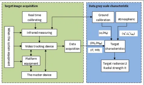
The most important function of the infrared character-istics measurement system based on image grayscale is to measure the infrared radiation characteristics of the target [2, 3, 12–20]. The operating principle of the sys-tem is shown in Fig.1.
In Fig.1, the symbols in the data processing block dia-gram of the target characteristics are as follows:
α—infrared radiation response measuring equipment; DN0—calibration deviation of dn0-infrared measuring
equipment;
τR′—target aircraft and the atmospheric transmittance between infrared measuring equipment;
LR′—target aircraft and infrared measuring equipment between atmospheric path radiation;
Lsky—Lsky-measured sky background brightness;
DNt—infrared measurement equipment to the target; DNbb—measured value of the standard calibration gray
body (or the infrared paint pod) of the dnbb-infrared measuring equipment;
IT—infrared measuring equipment integral time;
WB—infrared measuring equipment working band.
Fig. 1Schematic diagram of the model
Table 1Parameters of the test system detector
Working band 3.7μm~ 4.8μm
Detector type HgCdTe
Target surface size 640 × 512
Like size 15μm × 15μm
Cold screen number F F2
Frame frequency 50 Hz
Interface form CameraLink
NETD@22 °C 18mK
The measurement of infrared characteristics based on image grayscale includes two tasks: first, acquisition of target information and acquisition of target infrared digital image information. The second is the data pro-cessing of the target characteristics.
The process of target information acquisition is as follows:
Step 1: get the infrared image of the surface source gray body. The two-dimensional infrared measurement rotary table equipment can capture the target according to the guidance information, and then the servo tracking equip-ment can achieve precise tracking and measureequip-ment of the target through reasonable tracking means, and obtain the gray level of the surface source gray body (or the
infrared image gray level) and transmit it to the data ac-quisition and transmission equipment.
Step 2: acquire the target infrared image. The image grayscale is transmitted to the data acquisition and transmission equipment.
Step 3: import the gray image index of the two into the calculation model, get the relationship curve be-tween the gray value and infrared radiation value under specific target and specific condition, and invert the re-quired target radiation value according to the curve.
The data processing process of the target features is as follows:
First, calibration equipment of infrared measuring equipment is used to calibrate the radiation and
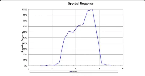
Fig. 2Spectral response curve of medium wave detector
determine the degree of infrared radiation response of the measuring equipment offset DN0 α and calibration.
By the target information acquisition process, infrared measuring equipment first obtain H0 height, horizontal
distance R0 of non-point source gray body infrared
image, thus calculate the distance measured atmospheric transmittance ofR0LR0,R0, and Cheng radiation. At the
same time, a laser radar, the temperature and humidity
meter atmospheric measurement equipment, was used so as to obtain highly H0 Ta aerosol extinction
coeffi-cient, temperature, and relative humidity RH, parame-ters, such as the provided MODTRAN software calculation theory of atmospheric transmittance R0 and theoretical path radiationLR0. As a result, get the
atmos-pheric transmittance correction coefficient C=R0, rou-tine radiation correction coefficientCp =LR0/LR0.
Then, the infrared characteristic of the target of dis-tance Ris measured, and the infrared image of the tar-get aircraft is obtained. Ta, RH, and according to the atmospheric parameters, by using MODTRAN software to calculate the distanceRtheory of atmospheric
trans-mittance R routine radiation LR and theory, and then
multiplied by the transmittance correction coefficientC
respectively and routine radiation correction coefficient
Cp, after correction of atmospheric transmittance
LR *R* and radiation.
Finally, using the infrared radiation response of meas-urement equipment, calibration after atmospheric trans-mittance LR*R and Cheng radiation, the gray value is measured by the target infrared radiation characteristics of inverse calculation target aircraft, such as radial brightness and radiant intensity.
3.2 The calibration model of infrared radiation measurement based on image grayscale is designed
Based on the calibration theory of infrared coating radi-ation measurement model, the model based on infrared target image is improved:
Lt¼
DNt−DN0
ð Þ=α− LR
0
LR00
LR0τ1þL1
τR
0
τR00τR0τ1
ð9Þ
From the above equation,Ltmeasurement accuracy de-pends on DNt, DN0,α, τR0,LR0, τR
0 τR00,
LR0
LR00,τ1, andL1. The
above uncertainty parameters are analyzed as follows: tar-get measurement output value DNtis better than 1%. The radiance response of infrared equipment DN0 is better
than 4.7%. Measured atmospheric transmittance based on infrared targetsτR0uncertainty is 10.5%. The uncertainty
of measured atmospheric path radiation based on infrared target is set at 12%., uncertainty is about 4.1%. The uncer-tainty of transmittance ratio and radiation ratio is 3.5%. According to the above analysis, the accuracy of the infra-red target inversion method is 49%. Compainfra-red with the traditional measurement model, the accuracy of the model is improved by 50%.
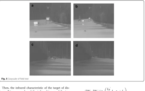
Fig. 5Grayscale of field test
Table 2Calibration results of FLIR mid-wave infrared camera
Integration time
IT = 0.5 ms IT = 1 ms IT = 2 ms
Calibration results
DN = 931 L + 245 DN = 1821 L + 558 DN = 3619 L + 1068
Table 3Measurement results of gray bodies at different temperatures at a distance of 100 m
The target distance
The target temperature (°C)
Target radiance
Target measurement
IT = 0.5 ms IT = 1 ms IT = 2 ms
100 m 45 1.926 2090 4150 8224
50 2.671 2618 5182 10,242
60 3.633 3296 6518 12,936
4 Radiation measurement results and discussions based on image grayscale
In order to verify the accuracy of the above model based on image gray level inversion calibration with higher measurement accuracy, related experiments are carried out in this paper.
4.1 The test methods and procedures
The test procedure is as follows:
In the laboratory using the infrared camera gray body radiation calibration, determine the camera radiation responsivityαand offset DN0;
In the external field, an infrared camera is used to measure the surface source gray body at a distance ofR0 to obtain the measured atmospheric transmittance and atmospheric radiation.
During the measurement period, the ground hori-zontal visibility Vis was obtained by using lidar, and the air temperature Ta and relative humidity RH were obtained by using temperature and humidity meter. According to these parameters, the theoretical atmos-pheric transmittance and path radiation between in-frared camera and gray body were calculated by using MODTRAN software.
Calculation of atmospheric transmittance correction coefficient and range radiation correction coefficient.
The gray body was placed in the distance infrared
camera (R), and the gray body was measured with the
infrared camera to obtain the infrared image of the distance R.
According to distance R, the theoretical atmospheric transmittance and path radiation between the mid-wave infrared camera and the gray body were calculated by using MODTRAN software, and the corrected transmit-tance and path radiation were obtained by multiplying the correction coefficient respectively.
Based on the radiation response of infrared camera de-gree α and offset DN0, respectively, using the theory of
atmospheric transmittance and routine radiation and the atmospheric transmittance and routine radiation after correction, the inversion of the gray body radial bright-ness, calculate the inversion error.
The experimental measurement system adopted is based on mid-wave infrared, which adopts the MW MimiCore HRC detector of FLIR company. The parame-ters, shape, and response curves of the detector are shown in Table1:
The spectral curve of the detector of the grayscale in-frared radiation measurement system is shown in Fig.2.
The optical system adopted by the measurement sys-tem is a transmission optical syssys-tem, and its main tech-nical indicators are as follows:
Mouth diameter: 80 mm;
Focal distance:f= 160 mm;
Visual field: 3.4°× 2.7°.
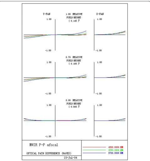
The advantages of the system are large field of view and good image quality. The aspherical transmission mirror can ensure good imaging quality in the larger field of view. The optical mechanical structure of the op-tical system is shown in Fig.3.
For the characteristic frequency of 16lp/mm, the dif-fraction limit is reached on the transfer function number axis of the optical system, the diffraction limit is nearly reached outside the axis, and the system distortion is less than 1%. The system aberration curve of the test system is shown in Fig.4.
4.2 Experiment and analysis based on image grayscale
In 2018, using FLIR mid-wave infrared camera and ISDC face source gray body, the project team carried out field test of radiation measurement method based on cali-brated gray body on a road with few pedestrians. The FLIR camera measures the gray body images of different distances as shown in Fig.5. In this figure, a is the 100 m gray body measurement image, b is the 200 m gray body measurement image, c is the 300 m gray body measurement image, and d is the 400 m gray body meas-urement image.
The grayscale radiation results of laboratory images of the FLIR mid-wave infrared camera are shown in Table2.
Table 3 shows the measurement results of the FLIR
medium wave camera at different temperatures of 100 m in different integral time.
Table 4Measured atmospheric transmittance at a distance of 100 m
The measured distance (m) IT = 0.5 ms IT = 1 ms IT = 2 ms
100 0.756 0.762 0.763
Table 5Theoretical atmospheric transmittance at various distances calculated by MODTRAN
The measured distance (m) MODTRAN transmittanceτα’
200 0.762
300 0.741
400 0.719
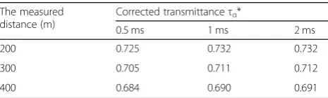
Table 6Corrected atmospheric transmittance
The measured distance (m)
Corrected transmittanceτα*
0.5 ms 1 ms 2 ms
200 0.725 0.732 0.732
300 0.705 0.711 0.712
Table 4 shows the measured atmospheric transmit-tance at a distransmit-tance of 100 m calculated from the mea-sured value of the gray body.
MODTRAN software is used to calculate 100 m from the theory of atmospheric transmittance 0.794; using the theory of 80.5 m of the measured atmos-pheric transmittance and atmosatmos-pheric transmittance, calculate the atmospheric transmittance correction coefficient.
Cτ=τa/τa'= 0.756/0.794 = 0.952 IT = 0.5 ms
Cτ=τa/τa'= 0.762/0.794 = 0.960 IT = 1 ms
Cτ=τa/τa'= 0.763/0.794 = 0.961 IT = 2 ms
The gray body is then measured at distances of 200 m, 300 m, and 400 m from the FLIR. By using MODTRAN software to calculate the distance of the theory of atmos-pheric transmittance ‘a. The atmospheric transmittance calculated by the model is shown in Table5.
Using transmittanceCτcorrection coefficientCof 200 m, 300 m, and 400 m theory of atmospheric transmit-tance,τa* =τa’×Cτ, as shown in Table6.
Then, using the theory of MODTRAN respectively at-mospheric transmittance τa’τ and revised the
atmos-pheric transmittanceτα*, to 200 m, 300 m, and 400 m in gray body target measurements of radiation inversion.
Table 7Inversion results of atmospheric transmittance after modification when IT = 0.5 ms
The target distance
Atmospheric transmittance
The target temperature (°C)
Target measurement
Target radiance
Inverse radiance The inversion error
MODTRAN Corrected transmittance
MODTRAN inversion radial brightness
Corrected inversion radial brightness
MODTRAN inversion error (%)
The revised inversion error (%)
200 m 0.872 0.826 44 2144 2.274 2.211 2.313 3.2 1.7
41 2471 2.771 2.729 2.773 1.7 3.4
71 3197 3.733 3.421 3.711 3.1 1.9
74 3479 4.219 4.147 4.274 3.7 1.3
300 m 0.832 0.806 44 2111 2.274 2.141 2.241 4.9 1.1
41 2342 2.771 2.491 2.719 7.7 2.1
71 2931 3.733 3.331 3.411 9.3 3.7
74 3274 4.219 3.931 4.127 9.1 4.3
400 m 0.829 0.783 44 2121 2.274 1.997 2.199 12.7 9.2
41 2243 2.771 2.337 2.444 12.4 9.1
71 2921 3.733 3.197 3.341 12.3 7.9
74 3173 4.219 3.711 3.999 12.1 7.7
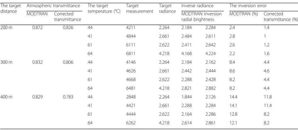
Table 8Inversion results of atmospheric transmittance after modification when IT = 1 ms
The target distance
Atmospheric transmittance The target temperature (°C)
Target measurement
Target radiance
Inverse radiance The inversion error
MODTRAN Corrected transmittance
MODTRAN inversion radial brightness
MODTRAN (%) Corrected transmittance (%)
200 m 0.872 0.826 44 4211 2.264 2.184 2.284 2.4 1.4
41 4844 2.661 2.484 2.611 2.8 1
61 6111 2.622 2.411 2.642 2.6 1.2
64 6811 4.218 4.168 4.224 2.2 1.6
300 m 0.832 0.806 44 4146 2.264 2.184 2.162 8.4 4.4
41 4626 2.661 2.442 2.444 8.6 4.6
61 4668 2.622 2.288 2.428 8.2 4.4
64 6481 4.218 2.821 2.882 8.2 4.4
400 m 0.829 0.783 44 2848 2.264 1.844 2.126 14.4 11.8
41 4421 2.661 2.288 2.284 14.1 11.4
61 4444 2.622 2.164 2.286 12.8 8.2
As shown in Table 7 for IT = 0.5 ms, the theory of
MODTRAN atmospheric transmittance τa’τ was used
and the atmospheric transmittance τa* in inversion
re-sults was revised.
The experiment USES different integral time of infra-red camera to extract gray image. Table 8shows the
in-version results of MODTRAN atmospheric
transmittance and modified atmospheric transmittance when IT = 1 ms.
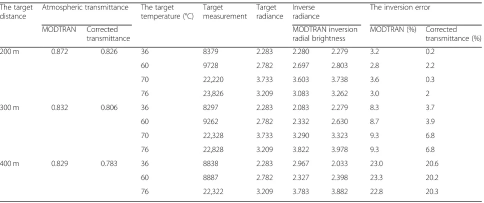
Three kinds of integral time were used to measure this experiment, respectively, and reasonable selection was made according to the difference of grayscale and con-trast. When IT = 2 ms is shown in Table9, the inversion results of MODTRAN atmospheric transmittance and modified atmospheric transmittance are used.
It can be seen from the results of the measurement based on image grayscale calibration model of 2D turn-table infrared radiation measurement inversion to cor-rection of measurements, the inversion error as the measuring distance is magnified by the increasing trend, but the correction of the model through the inversion error is significantly lower, you can think of model cali-bration on the infrared radiation calicali-bration of measur-ing device with high precision.
5 Conclusion
In this paper, the traditional indirect infrared radiation measurement model is improved, which is more suitable for remote dynamic target radiation measurement. In order to verify the accuracy of the model, a set of physical test system was established, and the model was validated by ground test. From the experimental results, the calibra-tion model based on image grayscale has high accuracy in infrared radiation measurement, and its quantitative measurement accuracy is improved by about 50%. Due to
the limited conditions, the ground verification method is adopted in this test, and only the infrared radiation meas-urement of a single-direction target is verified in space. For the target selection, aircraft, missiles, and other quick maneuvering targets are not adopted, but the targets with slow movement are adopted. In the following research, it is necessary to improve these experiments and adopt more direct physical objects for measurement verification and model modification. At the same time, it is very necessary to analyze the environmental conditions in the follow-up study. The influence of atmospheric environment on radiation accuracy is very large, and the measurement ac-curacy of different atmospheric permeability, visibility, temperature, humidity, and other environments changes greatly. A more accurate measurement model can be ob-tained by fitting the refined experimental values under the above atmospheric conditions.
Acknowledgements
The authors thank the editor and anonymous reviewers for their helpful comments and valuable suggestions.
Funding Not applicable.
Availability of data and materials Please contact author for data requests.
About the authors
Xue Xiangyao received M. Sc and Ph. D from Changchun Institute of Optics, Fine Mechanics and Physics, Chinese Academy of Sciences, and is associate research fellow in Changchun Institute of Optics, Fine Mechanics and Physics, Chinese Academy of Sciences now. His main research interests include structure design of fine optical mechanics and image process. Liu Chunxiang was born in 1983, and graduated in Changchun Institute of Optics, Fine Mechanics and Physics, Chinese Academy of Sciences, and is associate research fellow in Changchun Institute of Optics, Fine Mechanics and Physics, Chinese Academy of Sciences now. Her present research interests include photoelectric image, image process.
Qiao Jian was born in 1980, and graduated in Ji Lin University, and was associate research fellow in Changchun Institute of Optics, Fine Mechanics Table 9Inversion results of atmospheric transmittance after modification when IT = 2 ms
The target distance
Atmospheric transmittance The target temperature (°C)
Target measurement
Target radiance
Inverse radiance
The inversion error
MODTRAN Corrected transmittance
MODTRAN inversion radial brightness
MODTRAN (%) Corrected transmittance (%)
200 m 0.872 0.826 36 8379 2.283 2.280 2.279 3.2 0.2
60 9728 2.782 2.697 2.803 2.8 2.2
70 22,220 3.733 3.603 3.738 3.6 0.3
76 23,826 3.209 3.083 3.262 3.0 2
300 m 0.832 0.806 36 8297 2.283 2.083 2.279 8.3 3.7
60 9262 2.782 2.332 2.630 8.7 3.9
70 22,328 3.733 3.290 3.323 9.3 6.8
76 22,828 3.209 3.822 3.978 9.3 6.8
400 m 0.829 0.783 36 8838 2.283 2.967 2.033 23.0 20.6
60 8887 2.782 2.327 2.398 23.3 20.2
and Physics, Chinese Academy of Sciences, and is associate research fellow in Foshan University now. Her present research interests include Structure design of fine optical mechanics, Laser precision machining technology and Heavy-duty mobile robot.
Zhang Wenbao was born in 1967, and graduated in Qiqi Har University and is associate research fellow in Changchun Institute of Optics, Fine Mechanics and Physics. His main research interests include structure design of fine optical mechanics.
Li Ning was born in 1983, and graduated in Changchun Institute of Optics, Fine Mechanics and Physics, Chinese Academy of Sciences, and is associate research fellow in Changchun Institute of Optics, Fine Mechanics and Physics, Chinese Academy of Sciences now. His present research interests include photoelectric image.
Authors’contributions
All authors take part in the discussion of the work described in this paper. The author XX wrote the first version of the paper. The author LC carried out the experiments of the paper. QJ, ZW, and LN revised the paper in different versions. All authors read and approved the final version of the manuscript.
Competing interests
The authors declare that they have no competing interests.
Publisher’s Note
Springer Nature remains neutral with regard to jurisdictional claims in published maps and institutional affiliations.
Author details
1Changchun Institute of Optics, Fine Mechanics and Physics, Chinese Academy of Science, Changchun 130033, Jilin, China.2College of Mechanical Engineering, Foshan University, Foshan, China.
Received: 6 October 2018 Accepted: 7 January 2019
References
1. S. Hacohen, S. Shoval, N. Shvalbc, Applying probability navigation function in dynamic uncertain environments. Robot. Auton. Syst.87, 237–246 (2017) 2. S. Herzog, F. Wörgötter, T. Kulvicius, Generation of movements with
boundary conditions based on optimal control theory. Robot. Auton. Syst. 94, 1–11 (2017)
3. R. Iraji, S.M. Ghadami, Aids control using state-dependent Riccati equation. Sci. Int.27, 1183–1188 (2015)
4. Q. Jia, Y. Liu, G. Chen, H. Sun, State-dependent Riccati equation control for motion planning of space manipulator carrying a heavy payload. Open Mech. Eng. J.9(1), 992–999 (2015)
5. Y.L. Kuo, T.L. Wu, A suboptimal tracking control approach based on the state-dependent Riccati equation method. J. Comput. Theor. Nanosci.13, 1013–1021 (2016)
6. M. Mendesy, A.P. Coimbray, M.M. Crisostomoy, Assis-cicerone robot with visual obstacle avoidance using a stack of odometric data. IAENG Int. J. Comput. Sci.45, 219–227 (2018)
7. P.D. H. Nguyen, C.T. Recchiuto, A. Sgorbissa, Real-time path generation and obstacle avoidance for multirotors: A novel approach. J. Intell. Robot. Syst. 89, 27–49 (2018)
8. Ç. Tayfun, in The International Federation of Automatic Control, Statedependent Riccati equation (SDRE) control: a survey(2008), pp. 6–11 9. P.K. Menon, T. Lam, L.S. Crawford, V.H.L. Cheng, in American Control
Conference,Real-time computational methods for SDRE nonlinear control of missiles(2002), pp. 1–17
10. M.H. Hurni, P. Sekhavat, I.M. Ross, in AIAA Infotech Aerospace Conference AIAA,Issues on robot optimal motion planning and obstacle avoidance (2009), pp. 1–20
11. S.S. Mohammadi, H. Khaloozade, in 4th international conference on control, Instrumentation, and Automation,Optimal motion planning of unmanned ground vehicle using SDRE controller in the presence of obstacles(2016), pp. 167–171
12. S. Xie, P. Wu, Y. Peng, J. Luo, J. Gu, D. Qu, Q. Li, in Proceeding of the IEEE International Conference on Information and AutomationHailar,The obstacle avoidance planning of USV based on improved artificial potential field(2014), pp. 746–751
13. J. Slávka, S. Ján, in IEEE 11th International Symposium on Intelligent Systems and Informatics,Application of the state-dependent Riccati equation method in nonlinear control design for inverted pendulum systems(2013), pp. 26–28 14. F. Liccardo, S. Strano, M. Terzo, in World Congress on Engineering,Optimal
control using state-dependent Riccati equation (SDRE) for a hydraulic actuator (2013), pp. 3–5
15. S.M.H. Rostami, M. Ghazaani, State dependent Riccati equation tracking control for a two link robot. J. Comput. Theor. Nanosci.15, 1490–1494 (2018) 16. A. Hamdache, S. Saadi, A stochastic nominal control optimizing the
adoptive immunotherapy for cancer using tumor-infiltrating lymphocytes. Int. J. Dynam. Control.5, 783–798 (2017)
17. V.T. Wang, P.M. Hayes, Synthetic Aperture Sonar Track Registration Using SIFT Image Correspondences[C]. IEEE J. Ocean. Eng.42(4), 901-913 (2017) 18. S. Jiang, M. Lian, C. Lu, Q. Gu, S. Ruan, X. Xie, Ensemble prediction algorithm
of anomaly monitoring based on big data analysis platform of open-pit mine slope. Complexity (2018)doi.org/10.1155/2018/1048756
19. A.M. Yang, X.L. Yang, J.C. Chang, B. Bai, F.B. Kong, Q.B. Ran, Research on a fusion scheme of cellular network and wireless sensor networks for cyber physical social systems. Ieee Access6(99), 18786–18794 (2018)