R E S E A R C H
Open Access
Human recognition based on retinal images
and using new similarity function
Amin Dehghani
1*†, Zeinab Ghassabi
2, Hamid Abrishami Moghddam
3†and Mohammad Shahram Moin
4Abstract
This paper presents a new human recognition method based on features extracted from retinal images. The proposed method is composed of some steps including feature extraction, phase correlation technique, and feature matching for recognition. In the proposed method, Harris corner detector is used for feature extraction. Then, phase correlation technique is applied to estimate the rotation angle of head or eye movement in front of a retina fundus camera. Finally, a new similarity function is used to compute the similarity between features of different retina images. Experimental results on a database, including 480 retinal images obtained from 40 subjects of DRIVE dataset and 40 subjects from STARE dataset, demonstrated an average true recognition accuracy rate equal to 100% for the proposed method. The success rate and number of images used in the proposed method show the effectiveness of the proposed method in comparison to the counterpart methods.
Keywords:Human recognition; Harris corner detector; Retinal image; DRIVE and STARE dataset
1. Introduction
Nowadays, reliable, fast, and accurate recognition of a person is an important need for security systems, and recent advances in technology and increasing the need for security require the use of reliable biometric systems [1]. The biometric attributes used in security system for recognition include finger print, hand geometry, face, iris, and retina [2-8]. Each biometric feature has its strengths and weaknesses, and the choice depends on the application. Among these methods, the retina provides a higher level of security for recognition due to uniqueness and the stability of the blood vessel pattern during one's life. However, because of technological limitation in manufacturing specific imaging apparatus, its usage is limited to places where high security level is needed. Depending on the application context, a biometric system may operate in verification or identification mode. In the verification mode, the system confirms or denies a person's claimed identity by comparing the captured biometric features with the own biometric template(s) stored in the database. In the identification mode, the system recognizes an individual by searching the templates of all users in
the database for a match [9]. Therefore, for identification at first step, the security system must decide about the existence of a person. After confirming the existence, the security system must determine the identity of that person. Most recognition methods based on the retinal images are used only in identification or verification mode.
The first identification system using commercial retina scanner called EyeDentification 7.5 was proposed by EyeDentify Company in 1976 [10]. Some companies like Retica Systems Inc. are working on multi-modal security system using retina and iris for identification [11]. In Figure 1, an identification system based on iris scanner can be seen.
Recognition methods based on the retinal images are divided in two different classes. Some algorithms are based on the vessel segmentation results of retinal images. There-fore, the computational time of these methods is high. Some other algorithms are based on the features extracted from retinal images, and usually, the implementation time of these methods is low. Most of the last proposed methods are effective only for identification or verification mode. In this paper, a new identification and verification method based on the retina images is presented. The proposed method contains some steps including Harris corner detector for feature extraction, phase correlation technique to estimate the rotation angle of head or eye * Correspondence:[email protected]
†Equal contributors 1
Department of Electrical and Computer Engineering, University of Tehran, Tehran 14395-515, Iran
Full list of author information is available at the end of the article
movement in front of the retina fundus camera, and a new similarity function to compute the similarity between the features of dataset and test images. At first step, Harris corner detector is applied as a fast detector for feature ex-traction. On the other hand, the most important problem in using retinal images for human recognition is head or eye movement in front of fundus camera. The last proposed methods did not mention any solution for head or eye movement that may make mistake in the results of human recognition based on the retina images. In this paper, phase correlation technique is used to estimate and compensate the rotation angle of head or eye movement in front of the fundus camera. Finally, using a new similar-ity function, the similarsimilar-ity of each test image to each retina image of the dataset is determined.
The rest of the paper is organized as follows. Section 2 is devoted to the review of the last proposed methods for human recognition using retina images. In Section 3, Harris corner detector is used for feature extraction. Section 4 contains phase correlation technique to com-pensate the rotation angle of head or eye movement in front of the retina fundus camera. Section 5 is devoted to similarity function for feature matching. Recognition method and evaluation results are presented in Section 6. Finally, conclusion remarks are given in the last section.
2. Review of the last proposed methods
Farzin et al. [7] proposed a novel method based on the features obtained from retinal images. This method was composed of three principal modules including blood vessel segmentation, feature generation, and feature matching. Blood vessel segmentation module had the role of extract-ing blood vessel pattern from retinal images. Feature gen-eration module included optic disc detection and selecting circular region around the optic disc of the segmented image. Then, using a polar transformation, a rotation in-variant template was created. Next, these templates were
analyzed in three different scales using wavelet transform to separate vessels according to their diameter sizes. In the last stage, vessel position and orientation in each scale were used to define a feature vector for each subject in the database. For feature matching, they introduced a modified correlation measure to obtain a similarity index for each scale of the feature vector. Then, they computed the total value of the similarity index by summing scale-weighted similarity indices. The computational time of this method for segmentation, feature extraction, and matching is high, and this method was used only in identification mode.
Xu et al. [13] proposed a new method for recognition. They used the green grayscale ocular fundus image. At first step, the skeleton feature of optic fundus blood vessel using contrast-limited adaptive histogram equalization was extracted. After the filtering treatment and extracting shape feature, shape curve of blood vessels was obtained. Shape curve matching was later carried out by means of reference point matching. In their method for recognition, feature matching consisted of finding affine transformation pa-rameters which relates the query image and its best cor-responding enrolled image. The computational time of this algorithm is high because a number of rigid motion parameters should be computed for all possible corre-spondences between the query and enrolled images in the dataset.
Ortega et al. [14] used a fuzzy circular Hough transform to localize the optic disc in the retina images. Then, they defined feature vectors based on the ridge endings and bifurcations of vessels obtained from a crease model of the retinal vessels inside the optical disc. For matching, they used a similar approach as in [13] to compute the parameters of a rigid transformation between feature vectors which gives the highest matching score. This algorithm is computationally more efficient with respect to the algorithm presented in [13]. In [15], new methods were used to decrease the number of transformations instead of using points with specific distance from optic disc center. This method was used only in the verification mode.
Tabatabaee et al. [16] presented a new algorithm based on the fuzzy C-means clustering algorithm. They used Haar wavelet and snakes model for optic disc localization. The Fourier-Mellin transform coefficients and simplified moments of the retinal image was used as extracted fea-tures for system. The computational cost and implementa-tion time of this algorithm are high, and the performance of the algorithm has been evaluated using a small dataset.
Shahnazi et al. [17] proposed a new method based on the wavelet energy feature (WEF) which is a powerful tool of multi-resolution analysis. WEF can reflect the wavelet energy distribution of the vessels with different thickness and width in several directions at different wavelet
decomposition levels (scales), and thus, its ability to dis-criminate retinas is very strong. Simple computation was another virtue of WEF. Using semi-conductors and various environmental temperatures in electronic imaging systems cause noisy images, and thus, they used noisy retinal images for recognition. This method is based on the segmentation results of retinal images and was evaluated only on DRIVE dataset.
Oinonen et al. [18] proposed a novel method for verifica-tion based on minutiae features. The proposed method consisted of three steps: blood vessel segmentation, feature extraction, and feature matching. In practice, vessel segmentation can be viewed as a preprocessing phase for feature extraction. Then, vessel crossings and their orientation information were obtained. These data were matched with the corresponding ones from the comparison image. The method used the vessel direction information for improved matching robustness. The computational time of this method for segmentation, feature extraction, and matching is high, and this method was used in verification mode.
3. Feature extraction
Figure 2 shows the retina image, and it can be seen that the optic disc is the brightest region in the retina images [19]. Because of the existence of rotation in the retina image of a person in different situations and images, rotation invariant features are the best features for recogni-tion. Corners are rotation invariant, and they can be used as features for recognition. Therefore, corner detector method is used for feature extraction.
3.1 Corner detection algorithms
We consider the corner as the intersection of two edges or as a point that there are two dominant and different edge directions in its local neighborhood. There are several methods for corner detection [20-24]. Harris corner detector is one of the most well-known corner detectors and is based on measuring the corner strength. Compari-son between Harris corner detector and other corner de-tectors like SUSAN shows the superiority of Harris corner detector in the case of stability and complexity (running time) [25]. Therefore, Harris corner detector is used for feature extraction.
3.2 Harris algorithm
In the Harris corner detector, a window is slided on the image, and the change of intensity resulted from the sliding window is determined [21]. Therefore, the change E produced by displacement (x,y) in the image intensity I can be calculated using the following equation:
E xð ;yÞ ¼X
u
X
v wu;v Ix
þu;yþv−Iu;v
2
; ð1Þ
where w is the moving window. Harris corner detector looks for local maxima in min{E} found over all considered moving directions [21]. Now, the amount of displacement is expressed using the following equation:
E xð ;yÞ ¼X
u
X
v
wu;vIxþu;yþv−Iu;v2
¼X
u
X
v wu;v xX
þyYþO x 2;y2
2
; ð2Þ
where
X ¼Ið−1;0;1Þ≈∂I
∂x Y ¼Ið−1;0;1ÞT≈∂I
∂y:
ð3Þ
Other operators such as Sobel or Perwitt can be used for the gradient function in the above equation. Now for small displacement,Ecan be expressed as:
E xð ;yÞ ¼Ax2þ2CxyþBy2; ð4Þ
where
A¼X2w B¼Y2w C¼ðXYÞ w:
ð5Þ
To reduce the effect of the noise in the retina image, Gaussian window in the following form is used:
w uð ;vÞ ¼eðu2þv2Þ2σ2: ð6Þ
Optic Disc
Blood Vessel
Finally, we can expressEas:
E xð ;yÞ ¼ðx;yÞM xð ;yÞT; ð7Þ
whereMis a symmetric matrix in following form:
M¼ A CC B
: ð8Þ
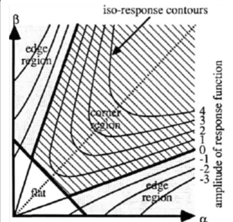
Eis closely related to the local autocorrelation function. Letαandβbe the eigenvalues ofM. Therefore, there are three situations. In Figure 3, all regions such as edges, corners, and regions with uniform intensity are described with respect to eigenvalues. In Figure 3, based on the (α,β) space, edges are in the regions where one of the eigen-values is very small and the other one is very large. Corners are in the regions where both eigenvalues are large, and in flat regions, both eigenvalues are small [21]. Harris and Stephens proposed the following corner measure:
R xð ;yÞ ¼Detð ÞM −kðTrð ÞM Þ2 Detð Þ ¼M αβ
Trð Þ ¼M αþβ:
ð9Þ
Contours of R are shown in Figure 3.R is positive in the corner region, negative in the edge region, and small in the flat region. Now, we apply threshold on the Rto find the corners. It is important to obtain only one corner for some points obtained as corners and is close to
each other. Therefore, the pruning algorithm is used. The proposed method for feature extraction is summarized as follows:
Step 1: Applying the gradient function inxandy direction.
Step 2: The matricesA,B, andCin Equation (5) are calculated.
Step 3: The convolutions ofA,B, andCwith Gaussian window in Equation (6) are calculated.
Step 4:Rin Equation (9) is obtained.
Step 5: Apply thresholding (Th) on the corners to eliminate the points which are not corners.
Step 6: Finally, for pruning the corners, a window is used around each point obtained after applying the threshold. Then, for each window, the point with the maximum value is considered as a corner.
Up to now, we localized the corners in the retina image as features. In Figure 4, corners in some retina images are shown (k= 0.17 and Th = 7 × 10⁴ and the size of window used in the sixth step is 7 × 7).
4. Rotation compensation
One of the most important problems in using retina images for recognition is the head or eye movement in front of the fundus camera. Therefore, a method based on the Fourier-Mellin transform is used to estimate the rotation angle of head or eye movement [26].
4.1 Phase correlation technique
Suppose thatfsandfrare the reference and input images that differ only by a displacement (x0,y0). Therefore,
fsðx;yÞ ¼frðx−x0;y−y0Þ: ð10Þ
If Fs and Frare the Fourier transforms of fs andfr, we may write:
Fsðu;vÞ ¼e−j2πðux0þvy0ÞFrðu;vÞ: ð11Þ
Figure 3Autocorrelation principal curvature space.Heavy lines give corner, edge, and flat classification, and fine lines are equi-response contours [21].
(a)
(b)
The cross-spectrum ofFsandFris defined as:
R¼ Frðu;vÞFsðu;vÞ Frðu;vÞFsðu;vÞ
j j¼ej2πðux0þvy0Þ; ð12Þ whereF*is the complex conjugate ofF. By taking the in-verse Fourier transform ofR, an impulse function is ob-tained:
F−1ð Þ ¼R δ x−x0;y−y 0
ð Þ: ð13Þ
By detecting the peak ofδ(x−x0,y−y0), the translation parameters (x0,y0) can be acquired.
4.2 Phase correlation technique for detection of translation and rotation
Iffs(x,y) is a rotated replica offr(x,y) with rotation angle
θ0and translation (x0,y0), then
fsðx;yÞ ¼frðxcosθ0−ysinθ0−x0;xsinθ0þycosθ0−y0Þ: ð14Þ
According to the property of Fourier transformation, the Fourier transforms Fs and Fr have the following relationship:
Fsðu;vÞ ¼e−j2πðux0þvy0Þ
Frðucosθ0−vsinθ0;usinθ0þvcosθ0Þ: ð15Þ
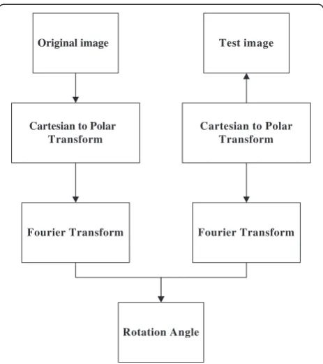
This means |Fs| is also a rotated replica of |Fr| with rotation angleθ0and without translation. The rotation angle can be obtained by representing the |Fs| and |Fr| with polar coordinates as shown in Equation (16):
Fsðρ;θÞ
j j ¼jFrðρ;θ−θ0Þj: ð16Þ
Then, the angle θ0 can be obtained by using phase correlation. The proposed method for estimation of the rotation angle is shown in Figure 5.
5. Similarity function
For recognition based on the corners obtained from vessel crossings, a new similarity function is used to match the features in dataset and test images. In con-trary to other methods such as proposed method in [14], instead of finding the similar points in two sets of points, at first step, a model that describes the relations between points in each set of points or image is used without needing to segment vessels in retina images. Then, we obtain the similarity between the model functions of different images to calculate the similarity between
the images. Therefore, in this method, the number of similar points in two different images does not play an important role in similarity results between two differ-ent images because the similarity between the model function of different images is determined for matching and recognition.
5.1 Model construction
To match interest points in different images, at first step, a model that describes the similarity between the points of each image is used [27]. Consider a set ofJinterest points in the source image as follows:
SF ¼ SF1;SF2;…;SFj;…;SFJ
SFj ¼ðx;yÞ:
ð17Þ
A rotation invariant coordinate system is used at each interest point SFj. Then, a set ofJfeature vectorsvjk=
(rjk, θjk) at each point j is formulated. (rjk, θjk) is the polar coordinate of the point with respect to the invariant coordinate system at the interest pointSFj.
rjk¼rj−rk
θjk ¼θj−θk k¼1;…;J ð18Þ
rjkis the distance between two interest points,SFj and
SFk.θjkcorresponds to the orientation of interest point
Original image Test image
Cartesian to Polar Transform
Cartesian to Polar Transform
Fourier Transform Fourier Transform
Rotation Angle
SFj to SFk. The similarity model between an unknown
vectorvand the feature vectors at pointSFjis given by:
SMvvj ¼
XJ
k¼1
Max exp −α v−vjk 2
:
ð19Þ
The function model SMjð Þv
describes the closeness and similarity of a given feature vector (v) to all the feature vectors around the interest point SFj andαis a constant
that takes different value. Therefore, using the Equation (18), we obtain a model that describes the closeness and relation between the corners in each set of points to obtain their similarities. Finally, Equation (19) is used to calculate the similarity between model function of different images obtained by Equation (18).
5.2 Matching
Assume that the source image (or reference image) has a set of J interest points as SF ¼ SF1;SF2;…;SFj;…;SFJ
andSFj¼ðx;yÞ, and using Equation (18), we compose the
matrix that describes the distance and orientation of points inSF to each other. Let the target image haveM interest points, TF ¼fTF1;TF2;…;TFMg and TFm ¼ðx;yÞ, and using the Equation (18), we compose the matrix that describes the distance and orientation of points in ST to each other. The matching between two sets of points (SFandTF) will be calculated using the following equations:
Matching¼X
J
i¼1 Ai
Ai¼Max SMvFivTj
M j¼1
:
ð20Þ
Therefore, using the above equations, the similarity of two retina images is calculated. For matching, we have two matrices, and we find the similarity between each element in the first matrix (obtained from the similarity of corners in first retina image) to all elements in the second matrix (obtained from the similarity of corners in the second retina image). The best match for the source image is when:
Matching>T; ð21Þ
whereTis a predetermined thresholding and is set to 0.3. In this paper, to decrease the computational time, onlyrjk
is used to compose model function.
6. Proposed method
Previous sections were devoted to feature extraction (using corner detector) and feature matching methods. This section explains the proposed method for recognition.
At the first step, for images of the dataset, the Harris corner detector is applied to extract corners as features.
The parameters used in the Harris corner detector are k= 0.17,Th= 7×10⁴, and a 7 × 7 window for pruning the corners, and corners with distance from the center of image is less than 190 pixels are used for recognition. Then, similarity model explained in Section 5 is used to formulate a set of vectors for each retina image.
6.1 Test images
As we know, the most important problem in using retinal images for recognition is head or eye movement in front of the fundus camera. We estimate the rotation angle of test image to each image in dataset images using phase correlation technique. Then, for each test image, we rotate it as the negative angle obtained using phase correlation technique to each dataset image. For the new image, we apply Harris corner detector and to decrease the compu-tational cost; corners with distance from the center of image is less than 190 pixels are used. Finally, we use the similarity model explained to obtain the similarity between the corners. Therefore, for each test image, some sets of similarity vectors and model functions based on the number of images in dataset are obtained.
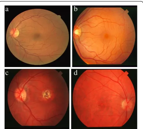
Figure 6Some of the retinal images in DRIVE and STARE dataset (a,b,c,d).
Table 1 Experimental results
Experiments Accuracy (%)
Experiment A 100
Experiment B 100
Experiment C 100
Experiment D 100
Experiment E 100
6.2 Recognition method
Our recognition method contains two steps. For each test image, we determined its rotation angle to each image in dataset, and we rotate the test image as negative angle obtained. Then, a region with 460 × 460 pixels around the center of new image is extracted. The absolute value of difference between the histogram of new rotated image and histogram of each image in dataset (region with 460 × 460
pixels around the center of image) is calculated, and we sum the results of different points to obtain a value for each test image to each image of the dataset. Now based on the situations,αin Equation (19) takes different values. If the result of difference between the histograms is less than 28,000, α = 0.25 else α = 1. Using the exponential function, we obtain similarity results in range of [0 1] for each test image.
0 0.1 0.2 0.3 0.4 0.5 0.6 0.7
0 10 20 30 40 50 60 70 80 90 100
Threshold
E
rro
r ra
te
(%
)
FAR
FRR
Figure 7FAR-FRR for different threshold in final step of matching, when difference between the histograms is 5 × 10⁴.
0 0.05 0.1 0.15 0.2 0.25
40 50 60 70 80 90 100
k
)
%(
et
a
R
n
oit
i
n
g
oc
e
R
na
m
u
H
6.3 Experiments
We applied the proposed algorithm on a database including 80 subjects, 40 images from DRIVE (565 × 584 pixels) [28], and 40 images from STARE (720 × 576 pixels) [29] data-base. We rotated randomly each image six times to obtain 480 images. We evaluated the performance of our recog-nition method in five different experiments as follows. In identification mode, at first step, the security system must decide about the existence of test image (person) in data-set. After confirming the existence, the security system must determine the identity of test person. For verification mode, the system confirms or denies a person's claimed identity. Then, if the similarity between the retina image of test person and retina image of person that test person claimed his (her) is larger than a predetermined threshold, the system confirms the person's claimed identity. For identification mode, all steps explained in Section 6.1 and 6.2 will be done. Then, similarity between the ret-ina image of test person and all retret-ina images in data-set is determined. Then, if the maximum similarity is more than predetermined threshold, it shows that the test images is one of retina images in dataset, and the image in dataset that causes the maximum similarity is the identity of test image. To obtain the threshold, we did a global scanning of different thresholds, and the best threshold for identification and verification mode is equal to 0.3.
6.3.1 Experiment A
The first 30 images of DRIVE database and the first 30 images of STARE were enrolled, and 80 images of DRIVE and STARE databases with six images per subject were entered to the system as queries.
6.3.2 Experiment B
The last 30 images of DRIVE database and the last 30 images of STARE were enrolled, and 80 images of DRIVE and STARE databases with six images per subject were entered to the system as queries.
6.3.3 Experiment C
The first 20 images of DRIVE database and the first 20 images of STARE database were enrolled, and 80 images from DRIVE and STARE databases with six images per subject were entered to the system as queries.
6.3.4 Experiment D
The first 25 images of DRIVE database and the last 25 images of STARE database were enrolled, and 80 images of DRIVE and STARE databases with six images per subject were entered to the system as queries.
6.3.5 Experiment E
Forty images of DRIVE database and 40 images of STARE database were enrolled, and 80 images from DRIVE and STARE databases with six images per subject were entered to the system as queries. Some of the retina images used in the propose method are shown in Figure 6. In Table 1, we can see the results of proposed method for different experiments.
These experiments demonstrated that the security system has an average accuracy equal to 100%. The proposed method on experiments performed in [8] has an average accuracy equal to 100% (these experiments are like experi-ments A to D with some difference in the dataset and also the number of images used for enrollment). Figure 7 shows the variation of FRR (false rejection rate) and FAR (false acceptance rate) for different thresholdings in the final
Table 2 Results of different recognition methods Accuracy (%) Number
of images
Number of subjects
Identification or verification mode
Running time (s) Method
Verification Identification
Dehghani et al. [1] 300 60 Identification - 0.06 99.75
3,600 99.78
Farzin et al. [8] 300 60 Identification - - 99
Xu et al. [13] - - Identification - 277.8 98.5
Ortega et al. [14] 90 83 Verification 0.155 - 100
Tabatabaee et al. [16] 108 27 Identification - -
-Shahnazi et al. [17] 400 40 Identification 3.34 100
Islam et al. [30] 18 6 Identification - - 100
Sukumaran et al. [31] 40 40 Identification - 3.1 98.33
Barkhoda et al. [32] 360 60 Identification - - 98
Barkhoda et al. [33] 440 40 Identification - - 99.75
Proposed method (corners and similarity function) 480 80 Identification (verification) 0.07 5.3 100 (100)
step of matching, when difference between the histograms is 5 × 10⁴.
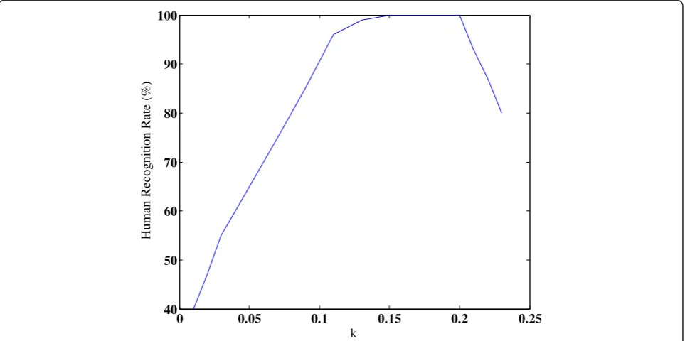
We can see from the Figure 7 that the proposed method is not sensitive to threshold in the range of [0.2 0.3]. Therefore, we can use thresholding for the final step in the range of [0.2 0.3]. In Figure 8, human recognition results based on the different values of k in Harris corner detector when the thresholding value of histograms is 5 × 10⁴ are shown. Therefore, it can be seen that the proposed method is not sensitive for k in the range of [0.15 0.2]. Now for better compari-son, the results of counterpart methods for recogni-tion and also dataset used are presented in Table 2. Most of counterpart methods can be used only in identification or verification mode, but the proposed method can be used in both identification and verifi-cation mode and its accuracy rate in these two modes is 100%.
7. Conclusions
In this paper, we proposed a new human recognition method based on corners and similarity function of retinal images without using vessel segmentation methods. The security systems based on their applications may perform in identification or verification mode. In the proposed method, in spite of other counterpart methods [8,13,14,29-32], segmentation methods that increase com-putational time were not used. We compensated the rota-tion angle of head or eye movement (gaze angle) in front of the retina fundus camera using phase correlation technique which was not mentioned in the counterpart methods. To extract corners in the retina image, Harris corner detector and some other steps such as applying threshold and pruning algorithm were used. In some situations that there is pathological region in the retinal images, Harris corner detector may not be effective, and in these situations, other corner detectors that may be effective must be used.
Then, corners that their distance from the center of image was less than 190 pixels were used to decrease the computational time of the proposed method. Finally, we used a similarity function with some limitation on its coefficient for recognition. The superiority of similarity function used in this paper is that, we obtained the simi-larity between the points in each set of points. Then using the similarity function, we estimated the similarity between two sets of points. In spite of other similarity function used in counterpart method [14], the number of similar points in two sets of points did not play an important role for recognition. The success rate and number of images used in proposed method show the effectiveness of the proposed method in comparison to the counterpart methods.
Competing interests
The authors declare that they have no competing interests.
Acknowledgments
This work was partially supported by Research Institute for ICT under grant no. T-500-4789.
Author details 1
Department of Electrical and Computer Engineering, University of Tehran, Tehran 14395-515, Iran.2Department of Computer Engineering, Science and Research Branch, Islamic Azad University, Tehran 46789-4113, Iran. 3Department of Electrical Engineering, K.N. Toosi University of Technology,
Seyed Khandan, Tehran 16315-1355, Iran.4Research Institute for ICT, Tehran 16846-13114, Iran.
Received: 25 January 2013 Accepted: 9 September 2013 Published: 31 October 2013
References
1. A Dehghani, H Abrishami Moghaddam, M-S Moin, Retinal Identification Based on Rotation Invariant Moments, inProceedings of the 5th International Conference on Bioinformatics and Biomedical Engineering(Wuhan, 2011) 2. ZM Kovacs-Vajna, A fingerprint verification system based on triangular
matching and dynamic time warping. IEEE Trans Pattern Anal Mach Intell. 22, 1266–1276 (2000)
3. A Kumar, D Zhang, Hand geometry recognition using entropy-based discretization. IEEE Trans. Inf. Forensics Security.2(2), 181–187 (2007) 4. G Anbarjafari, Face recognition using color local binary pattern from mutually independent color channels. EURASIP J Image Video Process. 2013, 6 (2013). doi:10.1186/1687-5281-2013-6
5. C-H Lin, J-L Chen, Z-L Gaing, Combining Biometric Fractal Pattern and Particle Swarm Optimization-Based Classifier for Fingerprint Recognition. Math. Probl. Eng.2010, 1–15 (2010). doi:10.1155/2010/328676 6. F Rossant, B Mikovicova, M Adam, M Trocan, A robust iris identification
system based on wavelet packet decomposition and local comparisons of the extracted signatures. EURASIP J Adv Signal Process.2010, 415307 (2010). doi:10.1155/2010/415307
7. B Nakissa, Shahram Moin M: A new user dependent iris recognition system based on an area preserving pointwise level set segmentation approach. EURASIP J Adv Signal Process.2009, 980159 (2009). doi:10.1155/2009/980159 8. H Farzin, H Abrishami Moghaddam, M-S Moin, A novel retinal identification
system. EURASIP J Adv Signal Process.2008, 280635 (2008). doi:10.1155/2008/280635
9. AK Jain, A Ross, S Prabhakar, An introduction to biometric recognition. IEEE Trans. Circuits Syst. Video Technol.14(1), 4–20 (2004)
10. RB Hill,Retinal identification(Biometrics: Personal Identification in Networked Society, Springer, Berlin, 1999), p. 126
11. Retica Systems. http://venturebeatprofiles.com/company/profile/retica-systems 12. Iris recognition. http://en.wikipedia.org/wiki/Iris_recognition
13. Z-W Xu, X-X Guo, X-Y Hu, X Cheng, The blood vessel recognition of ocular fundus, inProceedings of the 4th International Conference on Machine Learning and Cybernetics(Guangzhou, 2005), pp. 4493–4498
14. M Ortega, MG Penedo, J Rouco, N Barreira, MJ Carreira, Retinal verification using a feature points-based biometric pattern. EURASIP J. Adv. Signal Process.2009, 1–13 (2009)
15. M Ortega, C Marino, MG Penedo, M Blanco, F Gonzalez, Biometric authentication using digital retinal images, inProceedings of the 5th WSEAS International Conference on Applied Computer Science(Hangzhou, 2006), pp. 422–427 16. H Tabatabaee, A Milani-Fard, H Jafariani, A Novel Human Identifier System
Using Retina Image and Fuzzy Clustering Approach, inProceedings of the 2nd IEEE International Conference on Information and Communication Technologies(Damascus, 2006), pp. 1031–1036
17. M Shahnazi, M Pahlevanzadeh, M Vafadoost, Wavelet based retinal recognition, inProceedings of the 9th IEEE International Symposium on Signal Processing and Its Applications(Sharjah, 2007), pp. 1–4
18. H Oinonen, H Forsvik, P Ruusuvuori, O Yli-Harja, V Voipio, H Huttunen, Identity Verification Based on Vessel Matching from Fundus Images, in17th International Conference on Image Processing(Hong Kong, 2010), pp. 4089–4092
20. HP Moravec, Towards Automatic Visual Obstacle Avoidance, inProceedings of the Int’l Joint Conf Artificial Intelligence(Cambridge, MA, 1977), p. 584 21. C Harris, M Stephens, A Combined Corner and Edge Detector, inProceedings of
the Alvey Vision Conference(University of Manchester, 1988), pp. 147–151 22. A Noble, Finding corners. Image Vis Comput J.6(2), 121–128 (1988) 23. F Mokhtarian, R Suomela, Robust image corner detection through curvature
scale space. IEEE Trans Pattern Anal Mach Intell.20(12), 1376–1381 (1998) 24. E Rosten, T Drummond, Machine learning for high-speed corner detection,
inComputer vision - ECCV 2006, ed. by A Leonardis, H Bischof, A Pinz (9th European Conference on Computer Vision, Graz, 07–13 May 2006, Lecture Notes in Computer Science, vol. 3951, Springer, Heidelberg, 2006), pp. 430–443
25. J Chen, LH Zou, J Zhang, LH Dou, The comparison and application of corner detection algorithms. J Multimed.4(6), 435–441 (2009)
26. L Lin, Y Liu, Registration algorithm based on image matching for outdoor AR system with fixed viewing position. IEEE proc., Vis Image Signal Process. 153(1), 57–62 (2006)
27. K Krish, S Heinrich, WE Snyder, H Cakir, S Khorram, A new feature based image registration algorithm, inASPRS Annual Convention(Portland, OR, 2008) 28. A Dehghani, Abrishami Moghaddam H, Moin M-S: Optic disc localization in
retinal images using histogram matching. EURASIP J Image Video Process. 1, 1–11 (2012)
29. A Dehghani, M-S Moin, M Saghafi, Localization of the optic disc center in retinal images based on the Harris corner detector. Biomed. Eng. Lett. 2(3), 198–206 (2012)
30. MN Islam, MA Siddiqui, S Paul, An efficient retina pattern recognition algorithm (RPRA) towards human identification, inProceedings of the 2nd International Conference on Computer, Control and Communication
(Karachi, 2009), pp. 1–6
31. S Sukumaran, M Punithavalli, Retina recognition based on fractal dimension. IJCSNS Int J Comput Sci and Netw Secur.9(10), 66–7 (2009)
32. W Barkhoda, F Akhlaqian Tab, M Deljavan Amiri, Rotation invariant Retina identification based on the sketch of vessels using angular partitioning, in
Proceedings of the International Multiconference on Computer Science and Information Technology(Mragowo, 2009), pp. 3–6
33. W Barkhoda, F Akhlaqian, M–D Amiri, M-S Nouroozzadeh, Retina identification based on the pattern of blood vessels using fuzzy logic. EURASIP J Adv Signal Process.2011, 1–8 (2011)
doi:10.1186/1687-5281-2013-58
Cite this article as:Dehghaniet al.:Human recognition based on retinal images and using new similarity function.EURASIP Journal on Image and
Video Processing20132013:58.
Submit your manuscript to a
journal and benefi t from:
7Convenient online submission 7Rigorous peer review
7Immediate publication on acceptance 7Open access: articles freely available online 7High visibility within the fi eld
7Retaining the copyright to your article
![Figure 1 Iris scanner [12]. This figure shows the identificationsystems based on iris scanner.](https://thumb-us.123doks.com/thumbv2/123dok_us/917674.1589666/2.595.57.289.90.238/figure-iris-scanner-figure-shows-identificationsystems-based-scanner.webp)
![Figure 2 shows the retina image, and it can be seen thatthe optic disc is the brightest region in the retina images[19]](https://thumb-us.123doks.com/thumbv2/123dok_us/917674.1589666/3.595.57.292.485.715/figure-shows-retina-thatthe-brightest-region-retina-images.webp)