http://www.sciencepublishinggroup.com/j/epes doi: 10.11648/j.epes.20190805.15
ISSN: 2326-912X (Print); ISSN: 2326-9200 (Online)
Control Power Sharing of Parallel Inverters in Microgrid
with Consideration of Line Impedance Effect
Xuan Hoa Thi Pham, Toi Thanh Le, Hieu Tran Trong
Department of Electrical and Electronic Engineering, University of Food Industry, Ho Chi Minh City, Vietnam
Email address:
To cite this article:
Xuan Hoa Thi Pham, Toi Thanh Le, Hieu Tran Trong. Control Power Sharing of Parallel Inverters in Microgrid with Consideration of Line Impedance Effect. American Journal of Electrical Power and Energy Systems. Vol. 8, No. 5, 2019, pp. 127-144.
doi: 10.11648/j.epes.20190805.15
Received: October 2, 2019; Accepted: October 21, 2019; Published: October 25, 2019
Abstract:
This paper presents a power sharing control method for use between paralleled three-phase inverters in an islanded microgrid. In this study, the mismatch of power sharing when the line impedances have significant differences for inverters connected to a microgrid has been solved, the accuracy of power sharing in an islanded microgrid is improved, the voltage droop slope is tuned to compensate for the mismatch in the voltage drops across line impedances by using communication links. The method will ensure in accurate power sharing even if the communication is interrupted. If the load changes while the communication is interrupted, the accuracy of power sharing is reduced but the proposed method is better than the conventional droop control method. In addition, the accuracy of power sharing base on the proposed method is not affected by the time delay in the communication channel and local loads at the output of the inverters. The control model has been simulated in Matlab/Simulink with two or three inverters are connected in parallel. Simulation results demonstrate the accuracy of the proposed control method. Futhermore, in order to validate the theoretical analysis and simulation results, an experimental setup was built in the laboratory. Results obtained from the experimental setup verify the effectiveness of the proposed method.Keywords:
Droop Control, Power Sharing, Microgrid Control, Parallel Inverter, Line Impedance1. Introduction
In the microgrid, inverters are connected in parallel to form a backup system, improve the reliability, reduce the overload of each inverter, and provide flexibility. However, when a microgrid is operating in the islanded mode, each of the inverter should be able to supply its share of the total load in proportion to its rating. The control strategies for this mode are usually divided into two main types [1-2] as follows. The first type is made up of the communication-based control techniques including concentrated control, master/slave control and distributed control. These techniques can achieve an excellent proper power sharing. However, they required communication lines between the modules which may increase the cost of systems. Long distance communication lines are easy to disrupt, which reduces both system reliability and expandability. The second type is based on the droop control technique without requiring communications, and it is widely used in conventional power systems [2-11]. The reason for the popularity of this droop control technique is that it
provides a decentralized control capability that does not depend on external communication links. These techniques enable the “plug-and-play” interface and enhance the reliability of systems. However, communications can be used in addition to the droop control method to enhance the system performance without reducing reliability [12-22].
Traditional droop control techniques have some disadvantages in terms of power sharing for the following reasons:
1. The line impedances are not available and different from each other. Which has a significant effect on power sharing due to different voltage drops. When the impedances of the lines connecting inverters to the common connection point are different, a current imbalance appears when the load sharing error increases [1].
Moreover, with a heterogeneous line impedance, the active and reactive power interact with each other, which leads to difficulty for separate control [1].
3. Although frequency droop techniques can achieve accurate real power sharing, they typically result in poor reactive power sharing due to mismatches in the impedances of the DG unit feeders and the different ratings of the DG units [22-24]. Consequently, the problem of reactive power sharing in islanded microgrids has received considerable attention in the literature and many control techniques have been developed to address this issue [24-27]. Currently, the studies for power sharing between inverters have the following disadvantages:
4. Communication links are used in some droop improvement studies to enhance the accuracy of power sharing, but the implementation of this technique is sensitive to communication delays, delays in delivery can further reduce the accuracy of the power sharing [12-15].
5. The reliability of these studies are also affected when the communication is interrupted [16-22].
6. Improved power sharing methods can reduce the quality of the voltage, such as: virtual output impedance method [22]; droop method combined with signal injects [24]. 7. The accuracy of power sharing is enhanded negligible if
local loads are connected at the output of each inverter [25-26].
8. The line impedance parameters in these studies are either assumed to be reactance (X is much larger than R), or it is resistor (R is greater than X), but in fact the line parameters are including resistor and reactance, the power sharing results are not practical [27].
Currently, the problem of the reactive power sharing in the islanded microgrids has received a lot of considerable attention in the literatures and many control techniques have been developed to address this issue [28-30], where a mixed H2/H∞- based a voltage control loop, and a sliding-mode-control (SMC) - based a current loop, is used as
a replacement for the conventional
proportional-plus-integral-based cascaded control. This controller can improve the sustainability of the control system if the microgrid has nonlinear loads, unbalanced loads. However, the mathematical model for the SMC controllers is relatively complex, especially when there are local loads. Research [31] presented a method to reduce the burden on the calculation.
The focus of this paper is a proposed method for controlling parallel connected inverters in an islanded microgrid to allow for power sharing according to the ratio of the rated power of the inverters, under the following conditions:
1. There are significant differences in the line parameters from the inverters to the point of common coupling (PCC).
2. The microgrid has the local loads connected at the output of the inverters.
3. The communication is interupted or delay.
The DSOGI-PLL (Double Second Order Generalized Integrator - Phase Locked Loop) with a generalized integral block and phase lock loop to monitor the exact voltage magnitude and frequency phase at the PCC and support the information for proposed controller. Therefore, the proposed control method can be an alternative for load sharing control in islanded microgrids.
2. Islanded Microgrid Control
2.1. Structure of Islanded Microgrid
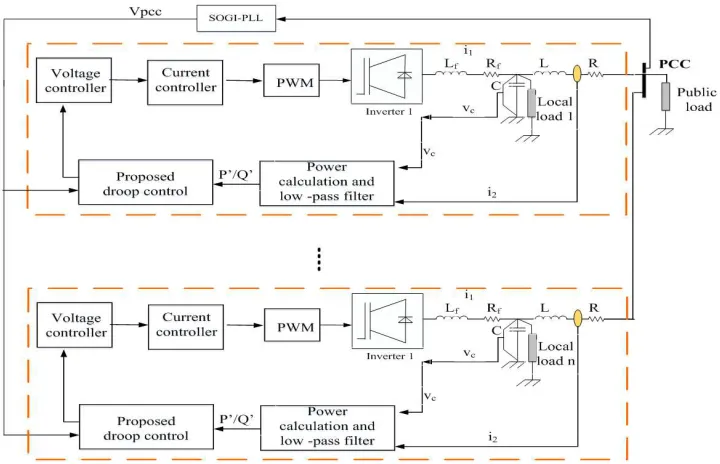
The structure of an islanded microgrid is made up of many inverters connected in parallel. A block diagram of inverters is provided, where each inverter is connected to a common bus at the PCC through the line impedance, is shown in Fugure 1. In addition, the loads of a microgrd are also connected to the common bus. The proposed controller contains two control loops, where the outer loop power control divides the capacity of each inverter and the inner loop control makes the voltage and current output of the inverters similar to the references. The voltage magnitude signal from the PCC are provided by a low-bandwidth connection. The inner loops are the current and voltage control to adjust the current and voltage at the inverter output.
Figure 1. Block diagram of inverters in an islanded microgrid.
2.2. The Principle of the Droop Control Method
The principle of the droop control method is explained by considering the equivalent circuit of an inverter connected to an AC bus. The analysis method is based on Thevenin theorem as shown in Figure 2.
The active and reactive power supplied by the inverter are calculated as follows:
= − + (1)
= − + − (2)
In general, both the inductance X and resistor R are considered. The use of an orthogonal linear rotational transformation matrix T from active power P and reactive power Q to active power P’ and reactive power Q’ is determined by:
= = −
+ (3)
When the power angle δ is small, equations (1), (2) and (3) can be rewritten as:
≅ #$$" ; − ≅ '" (4)
From (4), the basis of the well-known frequency and voltage droop regulation through active and reactive power is calculated by:
( = ()− *+ (5)
= )− *, (6)
where V0 and ω0 are the nominal amplitude voltage and
frequency of the inverter, respectively; VS and ω are the
measured amplitude voltage and frequency of the inverter, respectively; P and Q are the active power and the reactive power output of the inverter; P0 and Q0 are the nominal active
power of the inverter and the nominal reactive power of the inverter; and mp and mq are the active and reactive droop coefficients, which are calculated as follows:
*+=
ω-.ω/01
/23 ; *,= -. /01
'/23 (7)
The impedance of the lines connecting the inverters to the PCC is significantly different, the load sharing accuracy is difficult to achieve and the voltage adjustment is difficult since it depends on the parameters of the system. From (5) and (6), the following are obtained:
*,4 4= *,5 5= ⋯ = *,7 7= ∆ 9:; (8) *+4 4= *+5 5= ⋯ = *+7 7= ∆(9:; (9)
Combining the equations (1), (2), (3), (5), (6), (8) and (9), produces the conditions for accurately rated power sharing as in (10):
< = > = ?99@A@ =
A
4= 5
4= 5
9BA
9B =
A
(10)
To satisfy (10), it is necessary to choose droop coefficients that are proportional to the line impedance. If the system is adjusted to meet these requirements, the droop affects the quality of the frequency and voltage.
3. Proposed Control Strategy
In the paper, a controller is proposed to ensure the accurate power sharing of parallel inverters. The proposed controller is shown in Figure 3.
The proposed controller consists of the following main blocks:
3.1. The Proposed Reactive Power Sharing Controller
In this paper, the voltage droop slope is tuned to compensate for the mismatch in the voltage drops across line impedances by:
VDEF = kHI V − VJKK dt (11)
Where: V ' is the voltage at the output of the traditional Droop controller, which is determined by the Eq. (6).
V = V)− mO (12)
Where: kp is the gain of the integral, Vpcc is the voltage at PCC.
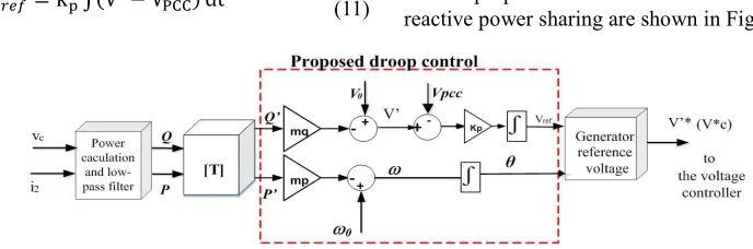
3.2. The Proposed Power Sharing Controller
The proposed controller to active power sharing and reactive power sharing are shown in Figure 4.
Figure 4. Proposed active power sharing and reactive power sharing control.
3.3. Survey the Stability of the Control System
From (1), (2), (3) and (4), we can write:
= #$$PQR S.S#$$ (13)
= . #$$TUP S.S#$$ (14)
where Vpcc are the output of DSOGI-PLL blocks, Vis the output of the reactive power sharing from the controller, and δ is the output of the active power sharing controller.
By linearizing (11), (12) and (14) around Q’, V and Vpcc the following is obtained:
∆ DEF = V+I ∆ − ∆ WX (15)
∆ = ∆ )− *,∆ (16)
∆ =Y'Y"∆ +YY'#$$" ∆ = Z∆ + [∆ (17)
Where:
Z =2 − cos −`
[ = − `cos −
The relationships among (15), (16) and (17) are shown in Figure 5.
Figure 5. Small signal reactive power sharing droop control.
The transfer function of Figure 5 is as follows:
∆ a = b@c
d [email protected]∆ ) a +
df.b@c
d [email protected]∆ a (18)
From (18), λ can be calculated as:
λ= −V+. *,. Z (19)
The transfer function (18) has shown that the constant of the loops control can be adjusted by kp, and not by mq. The reactive power sharing no longer affects the quality of the voltage or frequency.
By linearizing (5) and (13) around P’, δ and δpcc the
following is obtained:
∆( = ∆()− *+∆ (20)
∆ = g∆ + h∆ (21) Where:
g = cos −`
h = − ` cos −
∆ = g∆ + h∆ = g ∆ − ∆ (22)
The relationships among (20) and (22) are shown in Figure 6.
The transfer function of Figure 6 is as follows:
∆ a =d 9@. ∆() a +d 9@. ∆( (23)
From (23), λ can be calculated as: λ= −*+. g (24)
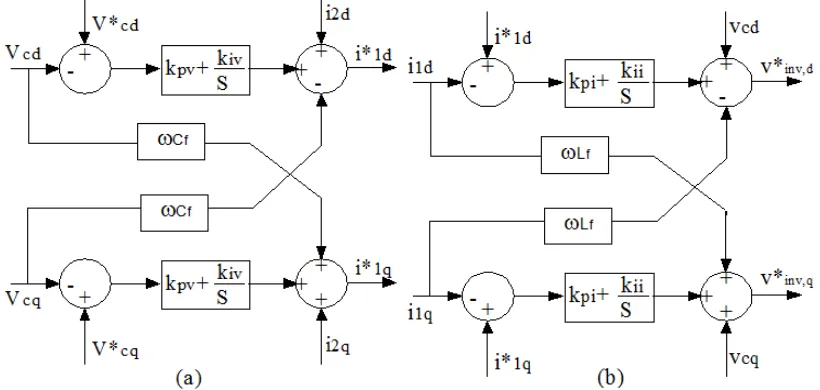
mp is determined by the Equation (7). 3.4. The Current and Voltage Controller The voltage and current controller employs standard proportional-integral (PI) regulators established based on the circuit equations from Equation (25) to Equation (28), which are written in the dq0 coordinates of the equivalent circuit as follows: 4i= 5i+ gijimkl− (gno, (25)
4, = 5,+ gijimkB+ (gnoi (26)
np7j,i= rFipimAl+ F 4i− (rF 4,+ noi (27)
np7j,,= rFipimAB+ F 4,+ (rF 4i+ no, (28)
Where i1d and i1q are the current of inverter; i2d and i2q are
the current on the line; and vcd and vcqare the voltage of the capacitor.
Figure 7. Schematics showing: (a) voltage controller; (b) current controller.
3.5. Modeling of a Three Phase DSOGI-PLL
Figure 8 shows the structure of a DSOGI-PLL. Both of the adaptive filtering technique and the in-quadrature phase detection technique are used in the DSOGI-PLL to generate the frequency and phase outputs. This system has a double
feedback loop, i.e. the frequency/phase generator provides both the phase-angle to the Park transform and the central frequency to the second order-generalized integrator - quadrature signal generation (DSOGI-QSG).
Figure 8. Modelling of a three phase DSOGI-PLL.
The parameters of the DSOGI-PLL are chosen as follows:
k= 2 , ts=100ms, ε=1 2 and 2.3 0.021s
2 =
=ts
Ti s .
Figure 9. Responses of a DSOGI-PLL.
Figure 9 (a) shows the frequency response of a DSOGI-PLL when the frequency of the input signal changes from 50Hz to 48Hz at t = 0.5s, and from 48Hz to 50Hz at t = 1s. Figure 9 (b) shows the frequency response of a DSOGI-PLL when the phase angle of the input signal changes from 0° to 45° at t=0.5s. Figure 9 (c) shows the response of the input and output voltages of a DSOGI-PLL. The simulation results in Figure 9 show that the DSOGI-PLL can obtain the exact voltage amplitude and frequency at the point of common coupling (PCC). The voltage amplitude is the input for the inner-controller. Therefore, when more exact values are obtained, more accurate power sharing is achieved.
3.6. Analyze the Effect of Local Loads on Reactive Power Sharing
Active power sharing based on frequency droop is not affected by local loads. However, local loads affecting reactive power sharing during islanding operation [15-28], is showed in Figure 10.
Figure 10. Reactive power flows of two inverters with local loads and line impedances are the same.
A number of things can be seen in Figure 10. When the microgrid does not have local loads, the slope kq1,2 is obtained
as follows:
V,4,5= -_A,'-_A,.- (29)
When the microgrid has local loads, the slope kq is obtained as
follows:
V,4,5= '-_A, -_A,.'-_tuk2tA.- (30)
Where:
V0: the nominal amplitude voltage at the PCC
V0_1,2: the nominal amplitude voltage of inverters 1, 2.
Q0_1,2:: the nominal reactive power of inverters 1, 2.
Q0_local 1,2: the nominal reactive power of local loads 1, 2.
Different local loads or different inverters leading to reactive power sharing is inaccurate as shown in Figure 11 and Figure 12.
Figure 11. Reactive power flows of two identical inverters and diffirent local loads.
Figure 12. Reactive power flows of two different inverters and different local loads.
According to Figure 11, when the microgrid has local load 1, the slope kq1 is obtained as follows:
V,4= '-_A,-_A,.'-_tuk2tA.- (31)
According to Figure 11, when the microgrid has local load 2,
0 0.2 0.4 0.6 0.8 1 1.2
40 50 60 70
f(Hz)
(a) t(s) I nput frequency Output
frequency
0 0.1 0.2 0.3 0.4 0.5 0.6 0.7 0.8 20
30 40 50 60 70 80
(b) t(s)
f(Hz)
I nput frequency
Output frequency
0 0.005 0.01 0.015 0.02 0.025 0.03 0.035 0.04 0.045 0.05 -5
0 5
Vabc(V)
the slope kq2 is obtained as follows:
V,5= '-_A,-_A.'-_tuk2t.- (32)
According to Figure 12, when the microgrid has local load 1, the slope kq1 is obtained as follows:
V,4= '-_A.'-_A-_tuk2tA.- (33)
According to Figure 12, when the microgrid has local load 2, the slope kq1 is obtained as follows:
V,5= '-_ .'-_-_tuk2t.- (34)
Figure 10, Figure 11 and Figure 12 shown that when microgrid has local loads at the output of the inverters, the local loads will make to changes the output voltage of the
inverters, the voltage of the local loads are equal to the voltage at the PCC. Therefore, the local loads make an offset in the output voltage of the inverters, which is the cause of mismatch for reactive power sharing in islanded microgrid.
By adjusting the integral gain coefficients kp for the
proposed controllers at the Equation (11), when it is in the set state, the voltages V' of inverters will come to an equal voltage (V'1 = V'2 =…V'n =VPCC). This means that the
deviation of the voltage drop across the line and the difference of the local loads are eliminated. In other words, the effect of the deviation of the line impedance and the difference of local loads are eliminated. As a result, if inverters are the same, local loads and line impedance are the same or different, the power sharing for each inverter is:
4= 5= 7=74v +wxypo+ yzo:y 4+ yzo:y 5+ ⋯ + yzo:y 7 { (35)
4= 5= 7=47v +wxypo+ yzo:y 4+ yzo:y 5+ ⋯ + yzo:y 7 { (36)
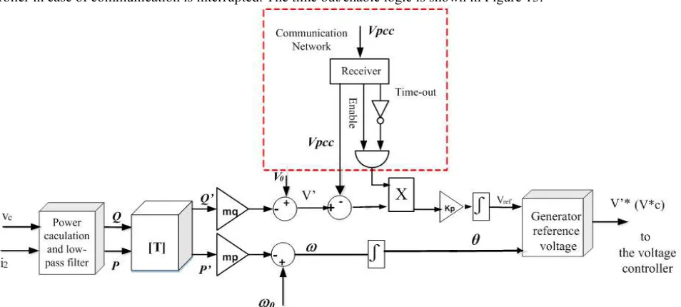
3.7. The Improve Proposed Controller
Proposed droop controller in Figure 4 was added to the block composed of logic gates in order to improve reliability for the controller in case of communication is interrupted. The time out/enable logic is shown in Figure 13.
Figure 13. Proposed active power sharing and reactive power sharing control is improved.
When the communication is interrupted, in which case the control loop is disabled and the integrator output will remain constant until the communication is restored. The amplitude voltage at output of proposed droop are held at the last value before the communication failure occurred due to the integral action of the controller. The power sharing is still accurate if the operating point remains unchanged after the communication failure, but if the load changes the power sharing error is still acceptable.
The time delay is called the information update delay. The proposed droop controller is immune to the time delay in the communication channel. Communication link only used to set the value of the reference voltage for tuning the output voltage
of the controller. Moreover, the reference voltage is the amplitude value therefore the system will reach steady state despite is slower than usual. If delays occur in steady state, it will not affect the power sharing accuracy. The reference voltage depends on the load so it is a fixed reference voltage until the load changes. Therefore, the accurate power sharing at steady state is unaffected by time delays in the communication channels.
4. Simulation Results and Discussion
Figure 1, is simulated in Matlab/Simulink. All of the simulation parameters of the system are given in Table 1.
Table 1. Parameters for the controllers.
Parameters Values Parameters Values
Input source voltage Vcd (V) 600 Rate frequency f0(Hz) 50
Filter inductance Lf(mH) 1.2 Rate power (kVA) 5
Filter resistance Rf(Ω) 0.2 Rate voltage VAC, p (V) 310
Filter capacitance C (µF) 50 Droop coefficient mq(V/Var) 1.7e-3
Switching frequency f0(kHz) 10 Droop coefficient mp (rad/s /W) 1e-4
4.1. Simulation for Power Sharing of Two Identical Inverters, the Line Impedances Are Difference
In this case, the line parameters of the two inverters are given in Table 2. The simulation results for this case including the real power output, reactive power output, current output and load voltage are shown in Figures 14 to 17.
Table 2. Line parameters of two inverters.
Line parameters Inverter 1 Inverter 2
Resistance R (Ω) 0.8 1
Inductance L (mH) 0.6 0.5
Figure 14. (a) Real power; (b) reactive power.
Figure 14 (a) and Figure 14 (b) show the real and reactive power sharing of each inverter, the power sharing performance is really good with the proposed strategy.
Figure 15 (a), Figure 15 (b) and Figure 15 (c) are shown response of phase current at output of inverter, we can see that during this time the controller has not reached the set state so there is a mismatch in the power sharing, so that the phase current is mismatch also.
0 2 4 6 8 10
0 500 1000 1500 2000 2500 3000 3500 4000
t(s) (a) P(W )
P1 P2
0 2 4 6 8 10
0 500 1000 1500 2000 2500 3000
t(s) (b) Q(Var)
Q1 Q2
0 0.05 0.1 0.15 0.2
-10 -5 0 5 10
i(A)
i1 i2
t(s) (a)
0.2 0.25 0.3 0.35 0.4
-10 -5 0 5 10
i(A)
i1 i2
Figure 15. The current output of inverters.
Figure 15 (d) is shown the response of phase current in satablity, the current sharing is not mismatched.
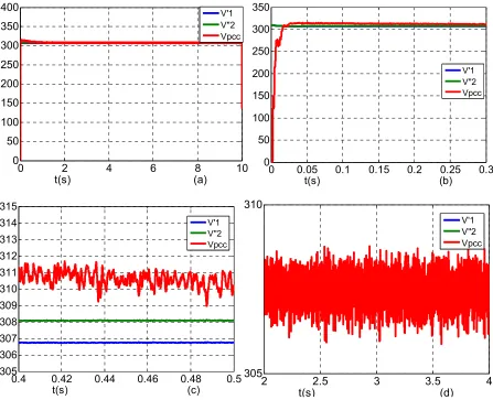
Figure 16. The voltage at PCC and voltage V 'of the proposed controller.
Figure 16 is shown the voltage at PCC and voltage V' of the proposed controller, Figure 16 (c) shows that when the proposed controller has not reached the set state, the voltage V'1 and the voltage V'2 are different, Figure 16 (d) shows that when the proposed controller has reached the set state, the voltages V'1, V'2, and Vpcc are equal, at this time the power sharing is not mismatch.
0.45 0.46 0.47 0.48 0.49 0.5
-10 -5 0 5 10
t(s) (c) i(A)
i1 i2
2.4 2.41 2.42 2.43 2.44 2.45
-10 -5 0 5 10
i(A)
i1 i2
t(s) (d)
0 2 4 6 8 10
0 50 100 150 200 250 300 350 400
t(s) (a)
V'1 V''2 Vpcc
0 0.05 0.1 0.15 0.2 0.25 0.3
0 50 100 150 200 250 300 350
t(s) (b)
V'1 V''2 Vpcc
0.4 0.42 0.44 0.46 0.48 0.5
305 306 307 308 309 310 311 312 313 314 315
t(s) (c)
V'1 V''2 Vpcc
2 2.5 3 3.5 4
305 310
t(s) (d)
Figure 17. The voltage at the output ot inverters.
Figure 17 shows the response of the voltages at the output of inverters, Figure 17 (b) shows the output voltages of the inverters are different, this is due to the mismatch of line impedances.
4.2. Simulation for Power Sharing of Two Identical Inverters, the Line Impedances Are Difference, the Loads Are Changed
In this case, the line parameters of the two inverters are given in Table 3.
Table 3. Line parameters of two inverters.
Line parameters Inverter 1 Inverter 2
Resistance R (Ω) 0.6 1.0
Inductance L (mH) 0.7 1.0
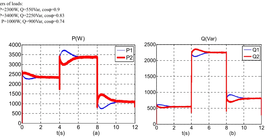
Parameters of loads:
t=0-4s: P=2300W, Q=550Var, cosϕ=0.9
t=4-8s: P=3400W, Q=2250Var, cosϕ=0.83
t=8-12s: P=1000W, Q=900Var, cosϕ=0.74
Figure 18. (a) Real power; (b) reactive power.
The deviation of active power and reactive power are divided:
|+% = 0. 0
∗
0∗ . 100% |,% =
'0.'0∗
'0∗ . 100%
Pi, Qi are the active power and reactive power measured at
the output of the inverter i
P*i, Q*i are the active power and reactive power desired
effect divided for the inverter i.
The deviation of active power in the period from 4s to 8s:
|+% = p− p ∗
p∗ . 100% =
3360 − 3350
3350 . 100% = 0,3%
The deviation of reactive power in the period from 4s to 8s:
|,% = p− p ∗
p∗ . 100% =
2255 − 2250
2250 . 100% = 0,22%
Figure18 shows that the proposed controller has result in good power sharing when the power of load varies.
0 2 4 6 8 10
0 50 100 150 200 250 300 350 400
t(s) (a) V (Voltage)
V1 V2
5 5.5 6 6.5 7
310 311 312 313 314 315 316
t(s) (b) V(V)
V1 V2
0 0.02 0.04 0.06 0.08 0.1 0
50 100 150 200 250 300 350 400
t(s) (c) V (Voltage)
V1 V2
0 2 4 6 8 10 12
0 500 1000 1500 2000 2500 3000 3500 4000
t(s) (a) P(W)
P1 P2
0 2 4 6 8 10 12
0 500 1000 1500 2000 2500
t(s) (b) Q(Var)
Figure 19. The current output of inverters.
Figure 19 (a) and Figure 19 (c) are shown response of phase current at output of inverter, we can see that during this time the controller has not reached the set state so there is a mismatch in the power sharing, so that the phase current is mismatch also.
Figure 19 (b) is shown the response of phase current in satablity, the current sharing is not mismatched.
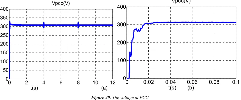
Figure 20. The voltage at PCC.
Figure 20 shows the voltage quality at the PCC, the voltage quality is always guaranteed by proposed controller.
4.3. Simulation for Power Sharing of Two Difference Inverters (P1: P2=2:1), the Line Impedances Are Difference
In this case, the line parameters of the two inverters are given in Table 4.
Table 4. Line parameters of two inverters.
Line parameters Inverter 1 Inverter 2
Resistance R (Ω) 0.4 0.8
Inductance L (mH) 0.6 1.0
Figure 21. (a) Real power; (b) reactive power.From Figure 21 (a) and Figure 21 (b), it can be seen that the proposed control method provides a good power sharing. Figure 21 can shows accurate real and reactive power with a 2:1 ratio.
0.3 0.305 0.31 0.315 0.32 0.325 0.33 -6
-4 -2 0 2 4 6 8
t(s) (a) i1 i2
2.05 2.06 2.07 2.08 2.09 2.1 -6
-4 -2 0 2 4 6 8
t(s) (b) i1 i2
4.18 4.19 4.2 4.21 4.22 -10
-5 0 5 10
t(s) (c) i1 i2
0 2 4 6 8 10 12
0 50 100 150 200 250 300 350 400
t(s) (a) Vpcc(V)
0 0.02 0.04 0.06 0.08 0.1
0 100 200 300 400
t(s) (b) Vpcc(V)
0 0.5 1 1.5 2 2.5 3 3.5 4
0 500 1000 1500 2000 2500 3000 3500 4000
P (W)
t(s) (a)
P1 P2
0 0.5 1 1.5 2 2.5 3 3.5 4
-1000 -500 0 500 1000 1500 2000 2500 3000 3500 4000
Q(Var)
t(s) (b)
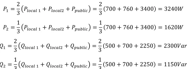
Total output power of each inverter:
4=23 v yzo:y 4+ yzo:y5+ +wxypo{ =23 700 + 760 + 3400 = 3240†
5=13 v yzo:y 4+ yzo:y5+ +wxypo{ =13 700 + 760 + 3400 = 1620†
4=23 v yzo:y 4+ yzo:y5+ +wxypo{ =23 500 + 700 + 2250 = 2300 ‡ˆ
5=13 v yzo:y 4+ yzo:y5+ +wxypo{ =13 500 + 700 + 2250 = 1150 ‡ˆ
4.4. Simulation for Power Sharing of Three Identical Inverters (P1: P2: P3=1:1:1), the Line Impedances Are Difference
In this case, the line parameters of the three inverters are given in Table 5.
Table 5. Line parameters of three inverters.
Line parameters Inverter 1 Inverter 2 Inverter 3
Resistance R (Ω) 0.8 1.0 0.7
InductanceL (mH) 0.6 0.8 0.5
Figure 22. (a) Real power; (b) reactive power.
Figure 22 (a) and Figure 22 (b) can be seen that the proposed control method provides a good power sharing. Figure 22 can shows accurate real and reactive power with a 1:1:1 ratio.
Figure 23. The current output of inverters.
0 2 4 6 8 10 12
0 500 1000 1500 2000 2500
t(s) (a) P(W )
P1 P2 P3
0 2 4 6 8 10 12
0 500 1000 1500 2000 2500
t(s) (b) Q(Var)
Q1 Q2 Q3
0.2 0.21 0.22 0.23 0.24
-4 -2 0 2 4 6 8
t(s) (a) i(A)
i1 i2 i3
2 2.01 2.02 2.03 2.04 2.05
-4 -2 0 2 4 6 8
t(s) (b) i(A)
Figure 23 (a) shows response of phase current at output of inverters, we can see that during this time the controller has not reached the set state so there is a mismatch in the power sharing, so that the phase current is mismatch also.
Figure 23 (b) is shown the response of phase currents in satablity the current sharing is not mismatched.
4.5. Simulation for Power Sharing of Two Identical Inverters, the Line Impedances Are Difference, the Communication Is Interrupted
In this case, the line parameters of the two inverters are
given in Table 6.
Table 6. Line parameters of two inverters.
Line parameters Inverter 1 Inverter 2
Resistance R (Ω) 0.8 1.2
Inductance L (mH) 0.6 1.0
The communication is interrupted at t=3s and the communication is restored at t=8s, the load are changed in the period from t=5s to t=8s.
4.5.1. Simulation Results with the Proposed Control
Figure 24. (a) Real power; (b) reactive power.
4.5.2. Simulation Results with the Conventional Droop Control
In order to improve the performance of the reactive power sharing under the effect of the line impedance, some simulation tests have been carried out with the same scenario as in the section 4.5.1. However, the conventional droop control method is applied as shown in (5) and (6). The simulation results are shown in Figure 25.
As shown in Figure 25 (a) and Figure 25 (b), the conventional method has a good performance for the case of a line impedances that are identical. However, in the case of the line impedances are difference, as shown in Table 6, the reactive power sharing is not accurate. The line impedance does not have an effect on the active power sharing. However, the line impedance have an effect on the active power sharing.
Figure 25. (a) Real power; (b) reactive power.
Figure 24a, Figure 24b show that in the period from 3s to 5s, although communication failure, but the load are not changed so the power sharing has been implemented correctly; in the period from 5s to 8s, the communication failure and the load
are changed so the reactive power sharing hasn't been implemented correctly, but still better than the conventional droop controller in Figure 25b. The communication be restored after the 8s, so the power sharing has been
0
1
2
3
4
5
6
7
8
9 10
0
1000
2000
3000
P(W)
t(s) (a)
P1
P2
Communication Failure
Communication restored
0
1
2
3
4
5
6
7
8
9 10
0
500
1000
1500
2000
Q(Var)
t(s) (b)
Q1
Q2
Communication restored
Communication Failure
0 1 2 3 4 5 6 7 8
0 500 1000 1500 2000 2500
P(W )
t(s) (a)
P1 P2
0 1 2 3 4 5 6 7 8
0 500 1000 1500 2000 2500
Q(Var)
implemented correctly.
4.6. Simulation in the Case of the Information Update Delay
Table 7. Line parameters of two inverters.
Line parameters Inverter 1 Inverter 2
Resistance R (Ω) 0.8 1.2
Inductance L (mH) 0.6 1.0
The line parameters of the two inverters for this simulation are provided in Table 7.
The effect of time delays in communication is investigated by introducing a delay in the signal sent to proposed controller 1, not delay for proposed controller 2. In this case, the proposed controller 2 receives the Vpcc reference and starts acting before proposed controller 1. Which has more effect on the transients in comparison to the case when the delays are identical. The introduced time delay is chosen as 0.02s, which is significant given that the reference update period is 200µs. Simulation results are illustrated in Figure 26 and Figure 27.
Figure 26. (a) Real power and reactive power when the proposed controller has not been delay; (b) Real power and reactive power when the proposed controller has been delay.
0.45 0.46 0.47 0.48 0.49 0.5
-10 -5 0 5 10
t(s) (a) i(A)
i1 i2
2.4 2.41 2.42 2.43 2.44 2.45 -10
-5 0 5 10
i(A)
i1 i2
Figure 27. (a) Current output when the proposed controller has not been delay; (b) Current output when the proposed controller has been delay.
The effect of time delays in communication is investigated by introducing a delay in the signal sent to proposed controller 2, not delay for proposed controller 1. The introduced time delay is chosen as 0.1s, a delay occurs at time t = 5s. Simulation results are illustrated in Figure 28.
Figure 28. (a) Real power and reactive power when the proposed controller has not been delay; (b) Real power and reactive power when the proposed controller has been delay.
Figure 26, Figure 27 and Figure 28 shown that the time delay has little effect on the system transients. Most importantly, the time delay does not affect the accurate power sharing of the proposed controller. If delays occur in a steady state as Figure 28, it
0.45 0.46 0.47 0.48 0.49 0.5
-15 -10 -5 0 5 10 15
t(s) (b) i(A)
i1 i2
2.4 2.41 2.42 2.43 2.44 2.45
-10 -5 0 5 10
t(s) (b) i(A)
i1 i2
5 5.5 6 6.5 7
3000 3100 3200 3300 3400 3500
t(s) (a) P(W )
P1 P2
5 5.5 6 6.5 7
2240 2250 2260 2270 2280 2290
t(s) (a) Q(Var)
Q1 Q2
5
5.5
6
6.5
7
3000
3100
3200
3300
3400
3500
t(s) (b)
P(W)
P1
P2
5 5.5 6 6.5 7
2240 2250 2260 2270 2280 2290
t(s) (b) Q(Var)
will not affect on the system transients.
The simulation results by the proposed controller are summarized in Table 8.
able 8. Reactive power sharing error for selected operating cases.
P1: P2
Conventional Droop
Proposed contoller
Communication available Communication Interrupted
The loads don’t change The loads change ∆Q1,2 (%) ∆Q1,2 (%) ∆Q1,2 (%) ∆Q1,2 (%)
1:1 24 0.22 0 1.33
2:1 67 0.22 0 3.4
The experimental results by the proposed controller by research [10] are summarized in Table 9.
Table 9. Reactive power sharing error for selected operating cases.
P1: P2
Conventional Droop
Proposed contoller
Communication available Communication Interrupted
The loads don’t change The loads change ∆Q1,2 (%) ∆Q1,2 (%) ∆Q1,2 (%) ∆Q1,2 (%)
1:1 24 0.43 1.47 2.96
2:1 67 0.43 5.4 8.6
Table 8 and table 9 show that the proposed controller has better results than the study [10]. However, if the communication bus is interrupted, and the load changes, the result of the reactive power sharing will give a significant deviation, but it is still much better than using a traditional controller.
Research [10] has not considered the effect of local loads in Microgrid on the proposed controller.
5. Hardware Implementation Using a
DSP
In this paper, a practical model has been developed for testing the proposed method. The developed hardware model consists of three 3-phase inverters, drivers of Semikron, LEM HX 20P and LV–25P are used as voltage and current sensors as shown in Figure 26. The proposed control method has been implemented on a TMS320F28335 DSP controller and the results obtained from the experiment have been captured by a Tektronix TDS2014B oscilloscope and a Fluke 345 PQ clamp
meter. To maintain the load demand, the three inverters have been used with a parallel output connection while RS485 lines are used as a communication network. The experiment has been carried out on three test cases with different ratios for real and reactive powers. The results obtained from the experiment have verified the advantages of the proposed control method through case studies.
5.1. Case Study 1: P1: P2: P3 = 1:1:3, and the Load Changes
This case corresponds to the ratio of the active powers being 1:1:3 and load changes with steps within pre-determined limits. The measured active power outputs for the three inverters are shown in Figure 30. The obtained active power outputs for the three inverters increase within the limits as P1min = 480W, P2min = 480W and P3min =
1450W P1max = 750W, P2max = 750 W, P3max = 2250 W. These results
have demonstrated the response capability of the system based on the new control strategy when the load continuously changes online with a constant ratio. The active power sharing errors for this case are very small.
Figure 30. Real power sharing.
5.2. Case Study 3: P1: P2: P3 = 1:1:1, Q1: Q2: Q3 = 1:1:1, and the Load Changes
Figure 31 shows the active and reactive powers of the three inverters in case of load changes. It can be seen that the ratio of the active and reactive powers is still kept at 1:1:1 when the load increases and decreases.
(a)
(b)
Figure 31. (a) Real power sharing; (b) reactive power sharing.
6. Conclusion
This paper has proposed a new method for an accurate load sharing ratio between the paralleled inverters in islanded Microgrids. In this study, the voltage droop slope is tuned to
compensate for the mismatch in the voltage drops across line impedances by using communication links. The method will ensure in accurate power sharing even if the communication is interrupted. If the load changes while the communication is interrupted, the accuracy of power sharing is reduced but the proposed method is better than the conventional droop control method. In addition, the accuracy of power sharing base on the proposed method is not affected by the time delay in the communication channel and local loads. Simulation results in Matlab/Simulink and hardware experiments have demonstrated the superiority of the proposed strategy in any case with any ratio.
Acknowledgements
The authors would like to acknowledge the support from the Power Electronics Research of HCMUT.
References
[1] Hua Han, Xiaochao Hou, Jian Yang, Jifa Wu, Mei Su, and Josep M. Guerrero, “Review of Power Sharing Control Strategies for Islanding Operation of AC Microgrids,” IEEE Trans. Smart Grid, Vol. 7, No. 1, pp. 200-216, Jan. 2016. [2] J. Rocabert, A. Luna, F. Blaabjerg, and P. Rodriguez, “Control
of power converters in AC microgrids,” IEEE Trans. Power Electron., Vol. 27, No. 11, pp. 4734-4739 Nov. 2012.
[3] Q.-C. Zhong. “Robust Droop Controller for Accurate Proportional Load Sharing Among Inverters Operated in Parallel,” IEEE Trans. Power Electron., Vol. 60, No. 4, pp. 1281-1291, Apr. 2013.
[4] [141] Md Alamgir Hossain, Hemanshu Roy Pota, Walid Issa and Md Jahangir Hossain “Overview of AC Microgrid Controls with Inverter-Interfaced Generations,” Energies, 30 August 2017.
[5] S. V. Iyer, M. N. Belur, and M. C. Chandorkar, “A generalized computational method to determine stability of a multi-inverter microgrid,” IEEE Trans. Power Electron., Vol. 25, No. 9, pp. 2420-2432, Sept. 2010.
[7] J. Hu, J. Zhu, D. G. Dorrell, and J. M. Guerrero, “Virtual flux droop method - A new control strategy of inverters in microgrids,” IEEE Trans. Power Electron., Vol. 29, No. 9, pp. 4704-4711, Sept. 2014.
[8] L. Y. Lu and C. C. Chu, “Consensus-based droop control synthesis for multiple DICs in isolated micro-grids,” IEEE Trans. Power Syst., Vol. 30, No. 5, pp. 2243-2256, Sept. 2015.
[9] J. He and Y. W. Li, “An enhanced microgrid load demand sharing strategy,” IEEE Trans. Power Electron., Vol. 27, No. 9, pp. 3984-3995, Sep. 2012.
[10] Hisham Mahmood, Dennis Michaelson, and Jin Jiang “Reactive Power Sharing in Islanded Microgrids Using Adaptive Voltage Droop Control,” IEEE Trans. On Smart gird, Vol. 30, No. 3, pp. 1605-1618 Mar. 2015.
[11] J. M. Guerrero, M. Chandorkar, T.-L. Lee, and P. C. Loh, “Advanced control architecture for intelligent microgrids - Part I: Decentralized and hierarchical control,” IEEE Trans. Power Electron., Vol. 60, No. 4, pp. 1254-1262 Apr. 2013.
[12] J. M. Guerrero, J. C. Vasquez, J. Matas, L. G. de Vicuna, and M. Castilla, “Hierarchical control of droop-controlled ac and dc microgrids - A general approach towards standardization,” IEEE Trans. Ind. Electron., Vol. 58, No. 1, pp. 158-172, Jan. 2011.
[13] J. C. Vasquez, J. M. Guerrero, M. Savaghebi, J. Eloy-Garcia, and R. Teodorescu, “Modeling, analysis, and design of stationary-reference frame droop-controlled parallel three-phase voltage source inverters,” IEEE Trans. Ind. Electron., Vol. 60, No. 4, pp. 1271-1280, Apr. 2013.
[14] M. Savaghebi, A. Jalilian, J. C. Vasquez, and J. M. Guerrero, “Secondary control scheme for voltage unbalanced compensation in an islanded droop controlled microgrid,” IEEE Trans. Smart Grid, Vol. 3, No. 2, pp. 797-807, May 2012. [15] M. A. Abusara, J. M. Guerrero, and S. M. Sharkh, “Line-interactive ups for microgrids,” IEEE Trans. Ind. Electron., Vol. 61, No. 3, pp. 1292-1300, Mar. 2014.
[16] H. Mahmood, D. Michaelson, and J. Jiang, “Accurate reactive power sharing in an islanded microgrid using adaptive virtual impedances,” IEEE Trans. Power Electron., Vol. 30, No. 3, pp. 1605-1617, Mar. 2014.
[17] J. He, Y. W. Li, J. M. Guerrero, J. C. Vasquez, and F. Blaabjerg, “An islanded microgrid reactive power sharing scheme enhanced by programmed virtual impedances,” in Proc. IEEE Int. Symp. Power Electron. Distrib. Gener. Syst. 2012, pp. 229-235.
[18] J. He, Y. W. Li, J. M. Guerrero, F. Blaabjerg, and J. C. Vasquez, “An islanding microgrid power sharing approach using enhanced virtual impedance control scheme,” IEEE Trans. Power Electron., Vol. 28, No. 11, pp. 5272-5282, Nov. 2013.
[19] K. S. Rangasamy College of Technology K. S. Rangasamy College of Technology Tiruchengode, Tamil Nadu, India Tiruchengode, Tamil Nadu, India, S. S. Balasreedharan, PG Student S. Thangavel, Professor Department of Electrical and Electronics Engineering, “India an adaptive fault entification scheme for DC Microgrid using event based classification,” Systems, Jan. 22 – 23, 2016.
[20] Mr. V. Prasad, M. Tech, M. I. M. E. S Assistant Professor,
Department of ECE, Shree Institute of Technical Education, Renigunta, Tirupati, “A Wireless Communication System for Data Transfer within Future Micro grids,” International Journal &Magazine of engineering, Vol, No. 3 (2016). [21] M. Farhadi, Student Member, IEEE and O. A. Mohammed,
Fellow, IEEE Energy Systems Research Laboratory, Department of Electrical and Computer Engineering Florida International University Miami, Florida, USA, “A New Protection Scheme for Multi-Bus DC Power Systems Using an Event Classification Approach,” 2015, IEEE.
[22] Mahdi Ashabani, Yasser A.-R. I. Mohamed, Senior Member, IEEE, Mojtaba Mirsalim, Senior Member, IEEE, and Mohammad Aghashabani, “Multivariable Droop Control of Synchronous Current Converters in Weak Grids/Microgrids With Decoupled dq-Axes Currents,” IEEE Transaction on Smart grid, Vol. 6, No. 4, 2015.
[23] Mr. Prakash D. Chavan, Prof. Rajan J. Devi, Department of Electronics Engineering, K. B. P. College of Engineering, Satara, Maharashtra, India Professor, Department of Electronics Engineering, K. B. P. College of Engineering, Maharashtra, “Survey of Communication System for DG’s and Microgrid in Electrical Power Grid,” International research Journal of Engineering and technology, Vol. 03, 2016.
[24] Bill Moran Senior Electrical Engineer TRC Companies Inc. Lowell MA, USA, “Microgrid Load Management and Control Strategies,” 2016 IEEE.
[25] Jae-Hyuk Kim, Yoon-Seok Lee, Hyun-Jun Kim and Byung-Moon Han, “A New Reactive-Power Sharing Scheme for Two Inverter-Based Distributed Generations with Unequal Line Impedances in Islanded Microgrids,” Energies, 8 November 2017.
[26] Made A. Setiawan, Student Member, IEEE, Farhad Shahnia, “ZigBee-Based Communication System for Data Transfer Within Future Microgrids,” IEEE Transactions on smart grid, Vol. 6, No. 5, 2015.
[27] Md Alamgir Hossain, Hemanshu Roy Pota, Walid Issa and Md Jahangir Hossain, “Overview of AC Microgrid Controls with Inverter-Interfaced Generations,” Energies, 30 August 2017. [28] Zhongwen Li, Chuanzhi Zang, Peng Zeng, Haibin Yu, Shuhui
Li, “Fully Distributed Hierarchical Control of Parallel Grid-Supporting Inverters in Islanded AC Microgrids,” IEEE Transactions on Industrial Informatics, 2017, Vol. 14, No. 2, pp. 679-690.
[29] Zhongwen Li, Chuanzhi Zang, Peng Zeng, Haibin Yu, Hepeng Li, ShuhuiLi, Analysis of Multi-Agent-Based AdaptiveDroop-Controlled AC Microgrids with PSCAD: Modeling and Simulation,” Journal of Power Electronics, 2015, Vol 15, No. 2, pp. 455-468.
[30] Zhongwen Li, Chuanzhi Zang, Jing Bian, “Control of A Grid-Forming Inverter Based on Sliding Mode and Mixed H2 /H∞ Control,”IEEE Transactions on Industrial Electronics, 2016,Vol 64, No. 5, pp. 3862-3872.