© Author(s) 2015. CC Attribution 3.0 License.
Experimental tests on operation performance of a LARM
leg mechanism with 3-DOF parallel architecture
M. F. Wang, M. Ceccarelli, and G. Carbone
LARM: Laboratory of Robotics and Mechatronics, DICeM-University of Cassino and South Latium, Cassino (Fr), Italy
Correspondence to: M. F. Wang ([email protected])
Received: 9 July 2014 – Revised: 17 December 2014 – Accepted: 13 January 2015 – Published: 30 January 2015
Abstract. In this paper, a prototype of a LARM leg mechanism is proposed by using a tripod manipulator and its operation performance is investigated through lab experimental tests. In particular, an experimental layout is presented for investigating operational performance. A prescribed motion with an isosceles trapezoid trajectory is used for characterizing the system behavior. Experiment results are analyzed for the purpose of operation evaluation and architecture design characterization of the tripod manipulator and its proposed prototype.
1 Introduction
Legged locomotion has a number of advantages as com-pared with conventional wheeled and crawler-type locomo-tion, such as higher mobility, better obstacle overcoming ability, energy efficiency, active suspension and achievable speed, especially when it operates in rough or unconstructed environment (Pfeiffer, 2004; Carbone and Ceccarelli, 2005; Siciliano and Khatib, 2008).
Biped locomotors, as a significant hot topic, have attracted interests of many research communities in the past decades, and a lot of prototypes have been built in the laboratories and even for specific application tasks (Carbone and Cecca-relli, 2005; Siciliano and Khatib, 2008). In addition, parallel manipulators are well known for higher payload capability, stiffness, accuracy and dynamic performance in contrast to traditional serial manipulators, and have been widely stud-ied both in industry and academia (Ceccarelli, 2004; Mer-let, 2006). However, most of the existing biped locomotors are based on leg designs with human-like architectures by using serial chain solutions, such as ASIMO (Sakagami et al., 2002), HUBO (Park et al., 2005), HRP (Kaneko et al., 2002) and so on. WL-16 (Waseda Leg-No.16) is a design that achieved world first dynamic biped walking as based on leg designs with Gough-Stewart parallel manipulators (Hashimoto et al., 2009). Ota et al. (1998) and Sugahara et al. (2002) have also proposed to use Gough-Stewart paral-lel manipulators for leg modules in other systems.
Neverthe-less, the potentiality of parallel manipulators for leg mecha-nisms has not been fully investigated, since the typical six degrees of freedom (DOFs) manipulators also suffer from some disadvantages, e.g., limited workspace, difficult me-chanical design, complex direct kinematics, and control al-gorithms. To overcome the above disadvantages, parallel ma-nipulators with fewer than six DOFs, namely reduced DOF manipulators, have been widely studied both in industry and academia (Tsai, 1999; Merlet, 2006). In the field of leg de-signs for biped locomotors, Ceccarelli and Carbone (2009) have investigated the possibility of using parallel manipula-tor mechanisms with less than six DOFs for leg designs as inspired from the human leg muscular system. It is worthy to note that several architectures of 3-DOF purely translational parallel mechanisms (TPMs) like Delta in Clavel (1988), Or-thoglide in Chablat and Wenger (2003), or others like those in Tsai and Joshi (2001) can be used for leg designs, since turning capability of the biped locomotors can be solved by the waist rotation.
rela-(a) (b)
Figure 1.A design of LARM tripod leg mechanism: (a) a prototype at LARM; (b) a kinematic scheme of 3-UPU parallel manipulator.
tively large required operation space and high cost of par-allelogram pairs containing S- or U-joints (where S and U stand for spherical and universal pairs, respectively) cannot be considered suitable for leg designs in biped locomotors. In addition, by comparing the four 3-DOF TMPs in the Tsai and Joshi (2001), the rail guides of linear actuators in 3-PUU TMPs (where P stands for a prismatic pair) make the fixed platform too large to be a waist for biped locomotors, while 3-RUU and UPU TMPs (where R stands for a revo-lute pair) can be expected to be useful for leg designs. Fur-thermore, Bhutani and Dwarakanath (2014) have presented a high-precision prototype as based on 3-UPU TMP and they validated the practical feasibility of this design in terms of repeatability and trajectory following accuracy for various payloads.
Although few existing prototypes of biped locomotors have been built as based on leg designs with 3-DOF TMPs, there are some other legged locomotors with 3-DOF leg mechanisms. Zhang and Li (2011) have presented a walk-ing locomotor as based on a 3-RPC parallel mechanism by a specific operation mode with two moving platforms. Wang et al. (2009) have proposed a quadruped/biped recon-figurable walking locomotor as based on four 3-UPU paral-lel leg mechanisms for quadruped walking and by converting them into two 6-SPU parallel mechanisms for biped work-ing. Pan and Gao (2013) have presented a hexapod walking locomotor for situations when a nuclear disaster happens and it is based on 3-DOF parallel mechanisms. In addition, paral-lel manipulators with 3-DOF, have been widely investigated for relevant applications and they have simpler structure and kinematics, larger workspace, and more convenient control with respect to hexapods (Merlet, 2006). Indeed, 3-DOF ma-nipulators could be enough for reducing the total cost and operations of leg mechanisms for biped locomotors.
At the Laboratory of Robotics and Mechatronics (LARM) of University of Cassino and South Latium, a research line is devoted to design and analysis of parallel mechanisms with reduced DOFs for multiple purposes, and several prototypes of parallel manipulators have been built with low-cost and
(a) (b)
Figure 2.A scheme of arrangement of U-joints: (a) in the upper plate (waist); (b) in the lower plate (foot).
Figure 3.Dimension parameters of the prototype in Fig. 1a.
easy-operation characteristics (Ceccarelli, 2012). Research activities have been carried out on both theoretical study and application aspects. A 3-DOF parallel manipulator has been proposed, studied and used as a novel design solution of a LARM tripod leg mechanism for a biped locomotor (Wang and Ceccarelli, 2013).
In this paper, a prototype of a LARM leg mechanism is presented as based on a 3-DOF parallel manipulator. The experimental layout of the foot motion control system is presented for experimental experiences. Operational perfor-mance of the proposed LARM tripod leg mechanism has been investigated by experimental tests. A fairly simple mo-tion with an isosceles trapezoid trajectory is prescribed for characterizing the system behavior. Experimental results are analyzed for the purpose of operation performance evalua-tion and architecture design characterizaevalua-tion of the proposed LARM tripod leg mechanism.
2 A LARM tripod leg mechanism
DOF Weight (kg) Dimension (L×W×Hmm) Step size (SL×SHmm ) Step cycle (s/step)
3 4.5 223×200×463 200×50 6
mechanism, there are eight links that are connected by six U-joints and three P-U-joints, and the DOFs of the mechanism can be calculated as 3 from the expression of Grübler–Kutzbach criteria
F =6(n−j−1)+
j X
i=1
fi (1)
Since the joint DOFs of each limb are equal to five, each limb provides one constraint to the moving platform. As shown in Fig. 1b, U-joints in each limb are arranged with two outer revolute joint axes that are parallel to each other and the two inner revolute joint axes that are parallel to one another, so that each limb provides one rotational constraint to the moving platform. A combination of three limbs in each leg completely constrains the moving platform from any instan-taneous rotation. Hence, since the limb constraints are in-dependent from each other, the moving platform possesses purely translational motion, as indicated in (Tsai and Joshi, 2000).
Additionally, the upper and lower three U-joints are in-stalled in equilateral triangle arrangement with one ahead and the other two rear, as shown in Fig. 2, where each three inner revolute axes are installed pointing to the corresponding cir-cumcenter of the triangle and the circumradiuses areraand rb, respectively.
The main specifications and details of mechanical design parameters of the LARM tripod leg mechanism are listed in Tables 1 and 2, as referring to dimension parameters in Fig. 3, whereL,W, andHare length, width and height of the mech-anism, respectively;SLandSHare step length and height of
the foot; Hw andHf are the thicknesses of waist and foot
plates; LfandWf are length and width of the foot,
respec-tively. In each limb, the distance between the rotation center of upper U-joint and waist plate is equal to the distance be-tween the rotation center of lower U-joint and foot plate, i.e. the half length of the universal joint, given by Duw=Duf.
The distance between the two rotation centers of U-joints, is the length of each limb that is indicated as li (i=1, 2, 3), with the initial value given asLi0, which determines the
ini-tial height of the proposed mechanism. Finally, the stroke of linear actuators is indicated asLs.
Since the LARM tripod leg mechanism is developed for biped locomotors, which will be capable of moving with flexibility and versatility in practical applications, during the activity for mechanical design, particular attention has been paid to characteristics for low cost solution, load capacity, easy operation, lightweight and compact design. The pro-posed solution is worked out by choosing proper commercial
Table 2.Mechanical design parameters of LARM tripod leg mech-anism (mm).
Hw Hf Lf Wf ra rb Duw=Duf Li0 Ls
10 3 122.4 106 100 50 25 403 100
products, which have been also used in design modelling, and by adopting aluminium alloy as the material for the plates of waist and foot for its stiffness, mass density, and cheap cost. For kinematic analysis, a static coordinate frame A: O-xyz and a moving coordinate frame B: P-uvw are assumed on the fixed base and moving platforms, and pointsOandP are the centers of platforms, respectively, as shown in Fig. 1b. A po-sition vectorp= [px, py, pz]T of a reference pointP in the center of moving platform is given for indexing walking per-formance. Theith (i=1, . . . , 3) actuated limb is connected to the moving platform at pointBi and to the fixed base at pointAi, whereAi andBi are the rotation center of corre-sponding U-joint. Furthermore, pointsAi (i=1, . . . , 3) lie on an equilateral triangle in the O-xy plane at a radial dis-tance ofra from point O, andBi (i=1, . . . , 3) lie on an equilateral triangle in the P-uv plane at a radial distance of
rb from point P. Hence, the position of the moving
plat-form and length of each limb can be respectively obtained in closed-form through the expressions as
px=
−2l21+l22+l23/6w
py=
l23−l22/2
√
3w
pz= q
l21−(px−w)2−py2 (2)
l1=
q
(px−w)2+p2y+p2z
l2=
r
(px+w/2)2+
py−
√
3w/22+p2
z
l3=
r
(px+w/2)2+
py+
√
3w/22+p2
z (3)
wherew=ra-rb, and the negative values for limb length and
root ofpzcannot be considered for this mechanism. Hence, the displacementLiof each linear actuator can be expressed as
X
Z Y
PC with MATLAB®, ARDUINO® and LABVIEW®
programs
Power supply and Controller
Spatial sensors
Prototype of LARM tripod leg mechanism
(a) (c) (b)
Z1 Y2
Z2 X2 X1
Figure 4.Layout for a foot motion control system of the proposed LARM tripod leg mechanism for experimental tests: (a) a layout of whole system; (b) a Phidgets®spatial 3/3/3 1044_0 sensor; (c) Location of two sensors.
A prototype of a LARM tripod leg mechanism
Part I Part II Part III
Prescribed movements
Motion pattern generator Manipulator control unit Instructions
Signal acquisition unit
S1
S2
Current
S3 S4
S5
Measured signals Signal processing unit
Test outputs
Figure 5.A schematic diagram of the experimental layout in Fig. 4 for an operation procedure.
3 An experimental layout and test modes
Figure 4 shows the foot motion control system of the pro-posed prototype of the LARM tripod leg mechanism for ex-perimental tests. In Fig. 4a, the leg mechanism is actuated by three linear actuators with 24V DC motors which are con-trolled by three AQMD2410NS DC motor drive cards with instructions from an ARDUINO card. Figure 4b shows a spa-tial Phidgets® sensor which has been used to measure ac-celeration, angular rate, and magnetic field strength in the Cartesian space. In Fig. 4c, two similar spatial sensors that are fixed on the linear actuator and the foot platform, respec-tively, are used for measuring the acceleration of linear ac-tuators along z axis and the angle information of the foot platform along three axes.
Figure 5 shows a scheme of the experimental operation procedure for the prototype of LARM tripod leg mechanism during experimental tests. The whole system consists of three parts: Part I is a motion pattern generator with suitable pro-gram running in MATLAB®environment; Part II consists of the manipulator control unit, signal acquisition unit, and PC with LABVIEW®software; Part III is the built prototype of the LARM tripod leg mechanism.
A controlled operation can be performed by following five steps (S1 to S5), which can be described as
– S1: it gives inputs of the motion generator for the leg mechanism of the prototype in Fig. 1a;
– S2: displacements for the three linear actuators are com-puted by using Eqs. (3) and (4) in MATLAB® environ-ment;
– S3: the computed motion trajectories in the motion pat-tern generator are transformed to control instructions in ARDUINO®environment, as the inputs of the manipu-lator controllers;
– S4: each limb follows the prescribed motion trajectory by driving DC motor of linear actuator under an open-loop control;
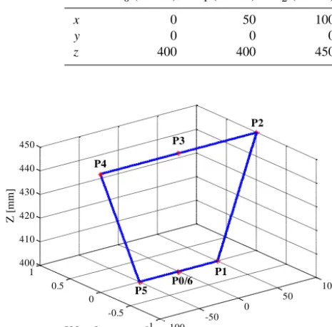
Axis P0(t=0 s) P1(t=1 s) P2(t=2 s) P3(t=3 s) P4(t=4 s) P5(t=5 s) P6(t=6 s)
x 0 50 100 0 −100 −50 0
y 0 0 0 0 0 0 0
z 400 400 450 450 450 400 400
-100 -50
0 50
100
-1 -0.5 0 0.5 1 400 410 420 430 440 450
X [mm] Y [mm]
Z
[
m
m
]
P5 P0/6
P1 P3
P2
P4
Figure 6.A prescribed input motion for experimental test.
4 Experimental test results
For human normal walking, the motion of a leg can be di-vided into two phases, i.e. a swing phase and a supporting phase (Carbone and Ceccarelli, 2005), and the human foot can be considered as the end-effector for a leg since it is moved to achieve proper motions and actions during the leg movements.
In general, the trajectory of a human-liked foot step is an ovoid curve where the straight line segment represents the supporting phase and the curve segment represents the swinging phase (Rose and Gamble, 2006). In this section, a prescribed input motion of foot platform has been consid-ered for experimental experiences, as shown in Fig. 6, where the curve segment is simplified by linear segments in O-XZ plane (Zielinska, 2004). Each step of the motion, whose tra-jectory actually is an isosceles trapezoid, is divided into six segments that are identified by seven prescribed positions, as shown in Table 3, where the start and end valuesP0and P6are equally given as the initial position of the foot motion.
Since the three linear actuators in the prototype are driven un-der a position and velocity open-loop control, the prescribed displacements are computed in MATLAB®environment and then they are transformed into ARDUINO® programs. The displacements of three linear actuators can be obtained ac-cordingly as shown in Fig. 7, where L2 and L3 are coincident because of the structure symmetry and no offset of the foot inyaxis, which can be easily obtained from Eq. (3).
0 1 2 3 4 5 6
0 10 20 30 40 50 60 70 80 90
Time [s]
D
is
p
la
ce
m
en
t
[m
m
]
L1 L2 L3
L1
L2 and L3
Figure 7.Input displacements of the three linear actuators.
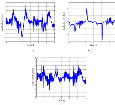
Figure 8 shows the measured rotation angles of the foot platform about three axes. It takes 6 s for the tested prototype to finish a prescribed movement. The foot platform rotates from−4.0 to 4.5◦aboutx
2axis and from−3.2 to 3.2◦about z2 axis, while it rotates from−14.1 to 10.9◦ abouty2axis.
In addition, the rotation angles abouty2 axis are normally
between from−7.5 to 3◦, and the two peak values only hap-pen at aboutt=2.2 s andt=4.1 s, i.e., close to pointsP2
andP4. From the test results with micro rotation angles of
the foot platform, it can be considered that the foot platform always maintains relatively translational motion but with cer-tain pitch at the extreme positions as pointsP2andP4.
Figure 9 shows the measured linear accelerations of the three linear actuators. According to the prescribed input mo-tions of the three linear actuators, as shown in Fig. 7, the motions of L2 and L3 should be the same, so that only linear accelerations of L1 and L2 are measured and plot-ted. Since the prescribed velocity of linear actuators in each segment is approximately constant, the accelerations should be approximately equal to zero, but at the beginning of each segment, i.e. at points Pi (i=0, . . . , 5) in Fig. 6, a sudden variation of acceleration occurs because of the ve-locity changes, which can be deduced by the input mo-tion in Fig. 7. In addimo-tion, maximum and minimum ac-celeration values of L1 and L2 are measured asAL1max=
(a) (b)
(c)
0 1 2 3 4 5 6
-5 -4 -3 -2 -1 0 1 2 3 4 5 Time [s] A n g le a b o u t X [ d eg ]
0 1 2 3 4 5 6
-15 -10 -5 0 5 10 15 Time [s] A n g le a b o u t Y [ d eg ]
0 1 2 3 4 5 6
-5 -4 -3 -2 -1 0 1 2 3 4 5 Time [s] A n g le a b o u t Z [ d eg ]
Figure 8.Measured rotation angles of the foot platform: (a) aboutx2axis; (b) abouty2axis; (c) aboutz2axis.
(a) (b)
0 1 2 3 4 5 6
-1.5 -1 -0.5 0 0.5 1 Time [s] A c c e le ra ti o n o f L 1 [m /s 2]
0 1 2 3 4 5 6
-1.5 -1 -0.5 0 0.5 1 Time [s] A cc el er at io n o f L 2 [m /s 2 ]
Figure 9.Measured axial linear acceleration alongzaxis for two linear actuators: (a) actuator L1; (b) actuator L2.
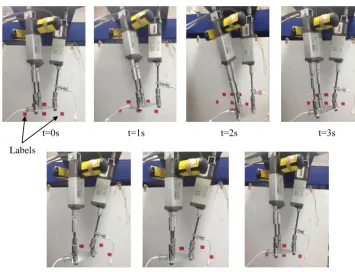
Figure 10 shows a sequence of leg configurations during an experimental test. Experimental test time has been indi-cated for each snapshot, which is coincident with the pre-scribed motion parameters in Table 3. It can be noted that the prototype starts from P0 and follows the prescribed
trajec-tory by six reference points, which are marked by red labels in Fig. 10.
t=0s t=1s t=2s t=3s
t=4s t=5s t=6s Labels
Figure 10.A sequence of snapshots of the prototype during a test following the prescribed motion for the test.
difficultly to maintain the relationship between U-joints in each limb during the operation, the motion of the foot plat-form has shown purely translational movements but with cer-tain pitch at the extreme positions for points P2 and P4 in Fig. 6. In addition, the precision of the proposed tripod leg mechanism is function of errors in mechanical design and control equipment. In particular, each of the used linear actu-ator consists of a 24 V permanent magnet motor that is cou-pled to an ACME lead screw whose lead is 2 mm and actua-tion error can be estimated in 0.2 mm. The motor drive card is based on current control whose resolution is 0.1 A and es-timated error is about 0.02 A. By considering the stroke and current range of the linear actuators, which are 100 mm and 1 to 7 A, respectively, the proposed arrangement provides rel-atively low control resolution along the prismatic motion to the limbs of the tripod leg mechanism. Nevertheless, since the tripod leg mechanism is built for a biped locomotor, small errors of rotation angles of the foot platform can be consid-ered acceptable during the practical application also because they give an operation that is comparable with human walk-ing. The experimental test results are also quite useful for identifying the operation performance of the prototype, vali-dating the mechanical design, and looking for enhancements.
5 Conclusions
A prototype of a LARM tripod leg mechanism has been built by using a 3-DOF parallel manipulator. The built prototype is a mechanical design solution with low-cost easy-operation features that can be useful for a tripod leg mechanism in a biped locomotor. Experimental tests have been performed successfully with the prototype to follow a prescribed step movement of the foot platform. Test results have validated the feasibility of the proposed design and have characterized its operation with suitable motion characteristics as a tripod leg mechanism for biped locomotors.
Acknowledgements. The first author would like to acknowledge China Scholarship Council (CSC) for supporting his PhD study and research at the Laboratory of Robotics and Mechatronics (LARM) in the University of Cassino and South Latium, Italy, for the years 2013-2015.
Edited by: A. Barari
References
Bhutani, G. and Dwarakanath, T. A.: Practical Feasibility of A High Precision 3-UPU Parallel Mechanism, Robotica, 32, 341–353, 2014.
Carbone, G. and Ceccarelli, M.: Legged Robotic Systems, Cutting Edge Robotics, ARS Scientific Book, Vienna, 553–576, 2005. Ceccarelli, M.: Fundamentals of Mechanics of Robotic
Manipula-tion, Kluwer Academic Publishers, Dordrecht, 2004.
Ceccarelli, M.: An Illustrated History of LARM in Cassino, in: Proc. of Int. Workshop on Robotics in Alpe-Adria-Danube Re-gion (RAAD), Naples, Edizioni Scientifiche e Artistiche, 85–92, 2012.
Ceccarelli, M. and Carbone, G.: A New Leg Design with Parallel Mechanism Architecture, in: Proc. of Int. Conf. on Advanced In-telligent Mechatronics (AIM), Singapore, 1447–1452, 2009. Chablat, D. and Wenger, P.: Architecture Optimization of A 3-DOF
Translational Parallel Mechanism for Machining Applications, the Orthoglide, IEEE Trans. Robot. Autom., 19, 403–410, 2003. Clavel, R.: Delta, A Fast Robot with Parallel Geometry, in: Proc. of the 18th Int. Symposium on Industrial Robots, Lausanne, 91– 100, 1988.
Hashimoto, K., Sugahara, Y., Lim, H. O., and Takanishi, A.: Biped Landing Pattern Modification Method and Walking Experiments in Outdoor Environment, J. Rob. Mechat., 20, 775–784, 2009. Kaneko, K., Kanehiro, F., Kajita, S., Yokoyama, K., Akachi, K.,
Kawasaki, T., and Isozumi, T.: Design of Prototype Humanoid Robotics Platform for HRP, in: Proc. of IEEE/RSJ Int. Conf. on Intelligent Robots and Systems (IROS), Lausanne, 3, 2431– 2436, 2002.
Merlet, J. P.: Parallel Robots (2nd Edn.), Springer, Dordrecht, 2006. Ota, Y., Inagaki, Y., Yoneda, K., and Hirose, S.: Research on a Six-Legged Walking Robot with Parallel Mechanism, in: Proc. of Int. Conf. on Intelligent Robots and Systems (IROS), Victoria, 241– 248, 1998.
Pan, Y., and Gao, F.: Payload Capability Analysis of A New Kind of Parallel Leg Hexapod Walking Robot, in: Proc. of Intl. Conf. on Advanced Mechatronic Systems (ICAMechS), Luoyang, 541– 544, 2013.
Park, I. W., Kim, J. Y., Lee, J., and Oh, J. H.: Mechanical Design of Humanoid Robot Platform KHR-3 (KAIST Humanoid Robot-3: HUBO). In: Proc. of IEEE/RAS Int. Conf. on Humanoid Robots (HUMANOIDS), Tsukuba, 321–326, 2005.
Pfeiffer, F.: Technological Aspects of Walking, in: Walking: Bi-ological and TechnBi-ological Aspects, edited by: Pfeiffer, F. and Zieli´nska, T., Springer, Wien, 119–154, 2004.
Rose, J. and Gamble, J. G.: Human walking (3rd Edn.), Lippincott Williams & Wilkins, Philadelphia, 2006.
Sakagami, Y., Watanabe, R., Aoyama, C., Matsunaga, S., Higaki, N., and Fujimura, K.: The Intelligent ASIMO: System Overview and Integration, in: Proc. of IEEE/RSJ Int. Conf. on Intelligent Robots and Systems (IROS), Lausanne, 3, 2478–2483, 2002. Siciliano, B. and Khatib O.: Handbook of robotics, Part G, Legged
Robots, Springer, Heidelberg, 361–390, 2008.
Sugahara, Y., Sugahara, Y., Endo, T., Lim, H. O., and Takanishi, A.: Design of a Battery-powered Multi-purpose Bipedal Loco-motor with Parallel Mechanism, n: Proc. Int. Conf. on Intelligent Robots and Systems (IROS), Lausanne, 3, 2658–2663, 2002. Tsai, L. W.: Robot Analysis: The Mechanics of Serial and Parallel
Manipulators, John Wiley & Sons, New York, 1999.
Tsai, L. W. and Joshi, S.A.: Kinematics and optimization of a spatial3-UPU parallel manipulator, ASME J. Mechan. Design, 122, 439–446, 2000.
Tsai, L. W. and Joshi, S.: Comparison Study of Architectures of Four 3 Degree-Of-Freedom Translational Parallel Manipulators, n: Proc. of the 2001 IEEE Int. Conf. on Robotics and Automation (ICRA), Seoul, 1283–1288, 2001.
Wang, H. B., Qi, Z. Y., Hu, Z. W., and Huang Z.: Application of Parallel Leg Mechanisms in Quadruped/Biped Reconfigurable Walking Robot, J. Mechan. Eng., 45, 24–30, 2009.
Wang, M. F. and Ceccarelli, M.: Design and Simulation for Kine-matic Characteristics of a Tripod Mechanism for Biped Loco-motors, in: Proc. of Intl. Workshop on Robotics in Alpe-Adria-Danube Region (RAAD), Portorož, 124–131, 2013.
Zhang, C. J. and Li, Y. W.: A New Walking Robot Based on 3-RPC Parallel Mechanism, Chinese J. Mechan. Eng., 47, 25–30, 2011 (in Chinese).