Transforming Simplified Requirement in to a UML Use Case Diagram
Using an Open Source Tool
R S Madanayake1, G K A Dias2 and N D Kodikara3
1, 2, 3 University of Colombo School of Computing, Colombo, Sri Lanka
1
[email protected], [email protected], [email protected]
ABSTRACT
While our main focus was on Modular Transformations and Ontologies we focused on a specific form of Modular Transformation, which arose due to the extremely rapid developments in the Software Engineering field, which led to the emergence of the Agile development processes, such as XP, SCRUM, Kanban, etc. A User Story is a tool popularly used in Agile software development. User Stories capture a description of a software feature from an end-user perspective. A User Story helps to create a simplified description of a requirement. UML Use Case diagrams overview the usage requirements for a system. A Survey done by us shows that greater percentage of organizations involved in software development use Unified Modeling Language (UML), Non-UML techniques for the analysis and design of their software projects. This means that there can be incompatibilities between them because their creators have different mindsets when constructing those models. Redundancy and unnecessary waste of time could be avoided, if other types of diagrams could be derived from one basic type. According to the analysis of our survey results, majority seems to be using Use Case diagrams, Class diagrams, Entity Relationship Diagrams (ERD) and User Stories. This paper describes a method that can be used in modular transformations to transform User Stories in to Use Case Diagrams using an open source tool.
Keywords: UML, User Stories, Use Cases diagrams, Modular Transformation, Open Source.
1. INTRODUCTION
There are considerable amount of compatibility issues when considering the tools and models used in different systems development methodologies. Their creators have different mindsets when constructing those models. This can lead to incompatibilities between them. During the process of system development this usually can lead to confusion. [1][2][3][4][5][6]
User stories are one of the primary development artifacts for project teams using Agile Processes such as Scrum,XP etc. A user story is a very high-level definition of a requirement, containing just enough information so that the developers can produce a reasonable estimate of the effort to implement it. [5][7][8]
In software and systems engineering, a use case is a list of event steps, typically defining the interactions between a role known in UML as an actor and a system, to achieve a goal.
However, we also came across circumstances where some have suggested that the Use Case models would be compatible with Epics which are large User Stories that contains collections of smaller User Stories. [9][10]. Several open source UML modeling tools were analyzed to identify a suitable tool that can be used for the diagram generation. Plant UML tool was selected for our experiment. PlantUML is an open-source tool allowing users to create UML diagrams from a plain text language. The language of PlantUML is an example of an Application Specific Language. It uses Graphviz software to lay out its diagrams. [11]
The aim of this publication is to describe a method that can be used in modular transformations to transform User Stories in to Use Case Diagrams using an open source tool with less interference.
1.1 Motivation
– Why are Modular Transformations needed at all?Two different surveys, one covering Sri Lankan, Singaporean and Australian IT Industries, [12] and another (done by us) concentrating exclusively on the Sri Lankan software development organizations, showed that some organizations use both UML as well as Non-UML Modelling methodologies (even if an Agile processes is followed) to help design their software. Redundancy and unnecessary waste of time could be avoided, if other types of diagrams could be derived from one basic type.
84% 16%
USE AGI LE METHODS?
Yes No
were involved for this purpose. Some questions asked with the % responses are given below.
Q1. Do you use Agile Methods / Processes?
Fig. 1. Usage of Agile Methods based on the survey done
According to Figure 1, 84% of the respondents use agile methods. Out of the 84% who uses Agile Methods, 51.9% say they use the popular Scrum Process where as 33.3% says they use a hybrid version (Mixture of different processes)
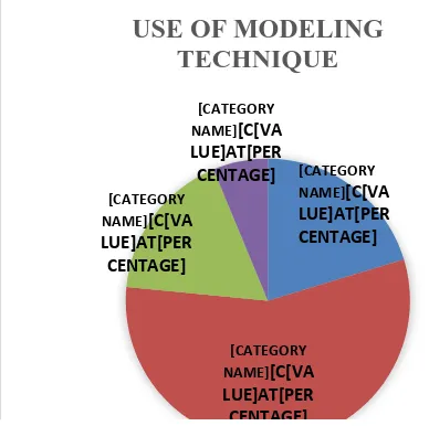
Q2. What modeling techniques do you use for
software engineering?
[CATEGORY NAME][C[VA LUE]AT[PER CENTAGE]
[CATEGORY NAME][C[VA LUE]AT[PER CENTAGE] [CATEGORY
NAME][C[VA LUE]AT[PER CENTAGE]
[CATEGORY NAME][C[VA LUE]AT[PER CENTAGE]
USE OF MODELING
TECHNIQUE
Fig. 2. Modelling Techniques used for Software Engineering based on the survey done
According to Figure 2 the majority (56%) seems to be using a mixture of UML and other modelling techniques for their projects. Out of the people who have responded for options b) and c), 79% uses Entity Relationship
Diagrams (ERD) whereas 55% are using User Stories for their projects.
Q3. What UML Diagrams do you use for modelling?
(From those who have answered Q2 (a) or (b))
Table 1: Usage of UML Diagrams based on the Survey
UML Diagram Usage %
a. Use Case Diagrams 32 86.5%
b. Class Diagrams 32 86.5%
c. Sequence Diagrams 21 56.8%
d. State Diagrams 13 35.1%
e. Activity Diagrams 20 54.1%
f. Component Diagrams 5 13.5%
g.Composite Structure Diagrams
1 2.7%
h. Deployment Diagrams 5 13.5%
i. Object Diagrams 3 8.1%
j. Package Diagrams 3 8.1%
k. Profile Diagrams 0 0%
l.Communication Diagrams
3 8.1%
m.Interaction Overview Diagrams
0 0%
n. Timing Diagrams 0 0%
Table 1 above shows the usage of UML diagrams based on a survey done exclusively on the Sri Lankan software development organizations.
Out of the respondents who have answered Q2 (a) and (b) majority seems be using Class (86.5%) and Use Case Diagrams (86.5%) for their projects.
For our Modular Transformation project we have given priority for the following popular diagrams and techniques for the initial stage based on the responses received for the questionnaire.
1) Use Case –86.5% uses Use Case diagrams 2) Use Stories – From those who answered Q2
options b)and c) , 55.1% uses User Stories 3) ERD – From those who answered Q2 options
b)and c) , 79.6% uses ERD diagrams
4) Class - From those who use UML diagrams 86.5% uses Class diagrams
In the survey done by the authors the following question was asked from those who are not using UML modeling.
Q4. If your answer to Q2) is d) (Do Not use
Modeling Techniques) what are the reasons for Not
using Modeling?
Answers given can be categorized as given in Table 2. .
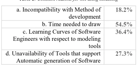
Table 2: Common reasons for not using modeling
a. Incompatibility with Method of development
18.2%
b. Time needed to draw 54.5%
c. Learning Curves of Software Engineers with respect to modeling tools
36.4%
d. Unavailability of Tools that support Automatic generation of Software
27.3%
According to Table 2, the majority (54.5%) have stated the reason „time needed to draw‟ is the common reason for not using modeling. Next highest response is for the reason „Learning Curves of Software Engineers with respect to modeling tools‟ (36.4%). Based on the Survey results authors strongly feel that if a user friendly tool can be developed for the modular transformation, it would greatly benefit the software development organizations. The tool also should have a steep learning curve.
In the case of Modular Transformations between User Stories and Use Case models, the Uexceler tool contained within the Visual Paradigm software [13] shows an attempt to link up the usage of Use Case models and User Stories with each other. After studying their approach authors were motivated further for a better solution for the mentioned problems in related to modeling.
2. METHODOLOGY AND RESULTS
A significant fact which first needs to be highlighted is that Use Case models and User Stories are both very important techniques in the Requirement Gathering Process of software development. Whether your project requires a User Story, Use Case, or both, will depend on the project, the available collaboration, the level of formality, and the upfront research required. “Some have found success in a hybrid, such as a highly detailed User Story, while others find the User Story as an important launching off point for the more detailed Use Case.” [14]
According to Segue [14], they tend to employ Use Cases mostly with government projects that have more rigid documentation requirements. For smaller projects having short duration they tend to lean towards User Stories. The many-years debate shows not so much that one is better than the other but that each can be applicable in varying degrees from project to project. Another important fact is that, although there are no distinct phases such as requirement gathering phase or design phase in agile processes, the need for efficient and effective requirement gathering is there, since the Industry develops software for clients / customers who have a low software development literacy.
2.1 Review of User story, Use Cases and Use Case
Narratives
In short, user stories are very slim and high-level requirements artifacts. It is a brief explanation of a software functionality from the user‟s perspective. [5] A use case describes a sequence of actions which will provide something of measurable value to an actor. [5] A Use Case Details or Use Case Narratives describe the process steps inside each use case. The narratives are needed because while it is great to see the features at a glance, no one really understands these process names mean until designers describe the steps in detail. If we told a developer of a library system to build a feature and all we gave them was the name “Issue Books”, they would have to ask questions and/or make lots of assumptions about how the librarian would interact with the system when he wanted to issue books. Those developers who actually read them love these narratives because they save so much time. Although there is no standard template for Use Case narratives, most templates found have the following details.
Name of the Use Case, Priority, System Actors, Preconditions, Course of Events, Alternative Course of Events, and Post conditions. [6][15]]16]
One such template describing the Use Case narrative for the Issuing of Books in a Library System based on the Case Study given for an experiment is given in Table 3. Experiment is described in Section 2.3.
Table 3: Use Case Narrative for the Issuing of Books in a Library System
Use Case Name Issuing Book
Priority High
Primary System Actors
Other participating Business Actors
Member
Precondition The Librarian should logged in to the system
Trigger The Member
Handover the copy to
the librarian
indicating the need to borrow it
Typical Course of Events
Librarian enters the borrower id.
System checks the validity of the member.
If member not exist (E-1) end use case.
Check for Overdue Books.
If yes (E-2) end use case
Check Over limit (E-3)
If yes (E-3) end use case
Enter copy id
Check Borrow able (E-4)
If No (E-4) end use case
Librarian Confirm Borrowing (C-5)
Update Borrowed Copy details
Alternative Flows
E-1 : Borrower id exist
E-2 : There are overdue books
E-3 : Borrower has already borrowed 5
books (max)
E-4 : Copy is not borrow able
C-1 : Confirm borrowing Message box
Post Condition If successful the Librarian issue the copy to the member
2.2 Identifying Actors and Use Cases from User
Stories
When looking at User Stories and Use Cases, one feature that would strike one would be that the role in a user story is similar to an actor of a use case model, while the goal or desire in a user story is similar to a use case. [17] However, instead of being directly related to User Stories, Use Case models maybe related to them through Epics. Epics are large User Stories which could be further decomposed into many smaller User Stories for the purpose of streamlining Software Development [17]. An Epic is a larger user story which is too big to implement in a single iteration and therefore need to be disaggregated into smaller user stories at some point. [5] We realized that even if User Stories may not be directly compatible with Use Cases, Epics which are larger and broader in scope maybe so.
2.3 Experiment conducted to determine the
Justification of the Compatibility between
Epics, Use Case Narratives and Use Case
Models
An Experiment was conducted with a sample of up to 160 Computer Science under graduate students. Students were given a Case Study and asked to develop User Stories followed by drawing the Use Case Model using the case study.
Results of this experiment was discussed earlier in another publication. [8]
User Stories : -
As a Librarian I want to
check the validity of the member
so that I can issue the book
As a Librarian I want to
check for overdue books so that I can issue the book
As a Librarian I want to check for Over-limit condition
so that I can issue the book
As a Librarian I want to
check whether the copy is a borrowable copy
so that I can issue the book
Epic :
As a Librarian I want to Issue books for members
so that members can borrow them
Use Case Diagram :
Fig. 3. Users Stories, Epics and the corresponding Use Case diagram Segment
2.4 Identifying Include Relationships From User
Stories
Based on the analysis done after the experiment we observed some connection between include relationship and the user stories.
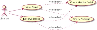
The example given below (Figure 4) illustrates the connection between User Stories, Epics and the include relationship in a Use Case model.
Say in a library, when a member wants to reserve a book, the librarian needs to do the following:
Check whether the member is valid (registered member)
Check whether the member has overdue books
When compare the user stories in Figure 3 and 4, the above two conditions are common. They can be shown in an include relationship as given in Figure 4 Use Case diagram.
User Stories : -
As a Librarian I want to check the validity of the member
so that I can reserve the book
As a Librarian I want to check for overdue books
so that I can reserve the book Epic : -
As a Librarian I want to Reserve a book for a member so that member can borrow it later
Use Case Diagram
Fig. 4. User stories, Epics and Use Case model with an include relationship.
2.5
Identifying
Extend
Relationships From User
Stories
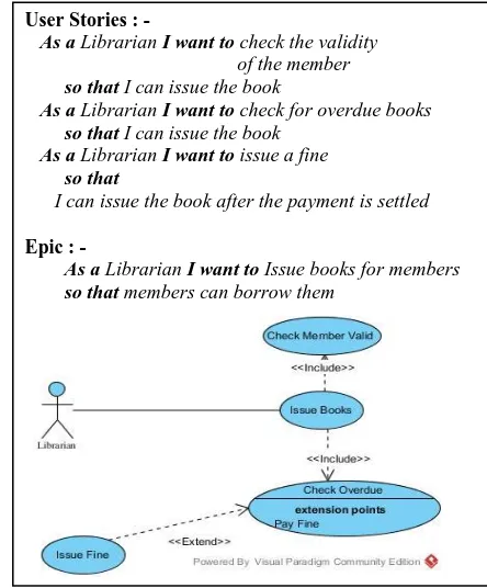
Say in a library, if the librarian found overdue books then he needs to Issue a fine. Since it is an optional behavior it can be shown as an Extend relationship. The Figure 5 illustrates the User stories, Epics and Use Case model with an Extend relationship as we suggest.
User Stories : -
As a Librarian I want to check the validity of the member
so that I can issue the book
As a Librarian I want to check for overdue books
so that I can issue the book
As a Librarian I want to issue a fine
so that
I can issue the book after the payment is settled
Epic : -
As a Librarian I want to Issue books for members
so that members can borrow them
2.6 Plant UML Software
Plant UML is a tool which allows users to generate UML diagrams from a plain text language.[11] The language used by Plant UML is called an Application Specific Language, since it only works for Plant UML. We will refer to this as the Plant UML coding language. Plant UML itself, is an open source software, and there are Plant UML plug-ins for a number of common software such as Eclipse, NetBeans, Microsoft Word, LaTex, etc. [11]
Our work was carried out using an installation of Eclipse, to which the relevant Plant UML plug-in was installed. Now let us briefly look at the syntax of the PlantUML coding language. Each block of Plant UML code starts with a @startuml statement and ends with a @enduml statement. The code in-between these two statements will decide what type of UML diagram that we are coding for. [11][18]
PlantUML code block which codes for a simple Use Case Model with one actor and one use case is given in Figure 6.
@startuml
left to right direction Librarian --> (Issue Books)
@enduml
Fig. 6. PlantUML code block which codes for a simple Use Case Model [11]
Use Case Model generated from the code of Figure 6 is given in Figure 7.
Fig. 7. Use Case Model generated from the code of Figure 6 [11]
2.6.1 How to generate the diagram from the
program source?
Once the above syntax (Figure 6) is typed in an untitled text file in Eclipse, the relevant UML diagram (Figure 7) is generated under the Plant UML tab of Eclipse. Another example is given below (Figure 8), which shows how the Include relationship is shown in Plant UML:
@startuml
left to right direction Librarian --> (Issue Books)
(Issue Books) ..> (Check Member Valid) : <<Include>> (Issue Books) ..> (Check Overdue) : <<Include>> Librarian --> (Reserve Books)
(Reserve Books) ..> (Check Overdue) : <<Include>> (Reserve Books) ..> (Check Member Valid) : <<Include>>
@enduml
Fig. 8. PlantUML code block which codes for Use Case Model which has Include relationship [11]
The syntax “..>” specifies an Include relationship between two use cases (Figure 8) and the code is used to generate the diagram shown in Figure 9 using Eclipse with the PlantUML plug-in.
Fig. 9. Use Case Model generated from the code of Figure 6 [11]
The next example (Figure 10) shows the Extend relationship through Plant UML: -
@startuml
left to right direction Librarian --> (Issue Books)
(Issue Books) ..> (Check Member Valid) : <<Include>> usecase c1 as "Check Overdue
--
<b>extension points</b> Pay Fine”
(Issue Books) ..> (c1) : <<Include>> (c1) <.. (Issue Fine) : <<Extend>>
@enduml
Fig. 10. PlantUML code block which codes for Use Case Model which has Extend relationship [11]
The syntax “<..” specifies an Extend relationship between two use cases. (Figure 10) Here, “c1” is an alias used for the “Check Overdue” use case, in order to give a more detailed view of that use case.
Fig. 11. Use Case Model generated from the code of Figure 10 [11]
The final example below (Figure 12), shows the Generalization relationship: -
@startuml
left to right direction
Librarian --> (Accept Payment)
(Accept Payment) <|-- (Accept Cash Payment) : <<Inheritance>>
(Accept Payment) <|-- (Accept Credit Card Payment) : <<Inheritance>>
(Accept Payment) <|-- (Accept Mobile Phone Payment) : <<Inheritance>>
@enduml
Fig. 12. PlantUML code block which codes for Use Case Model which has generalization relationship [11]
The actor is “Librarian”, and the use cases are “(Accept payment)” and “(Accept credit card payment)”, etc. (Figure 12)
The syntax “<|--” specifies an Inheritance relationship between two use cases.
Once the above syntax is typed in an untitled text file in Eclipse, the relevant UML diagram (Figure 13) is generated under the Plant UML tab of Eclipse.
Fig. 13. Use Case Model generated from the code of Figure 12
2.7 Open Source Software to transform Roles and
Goals / Desires of Epics into Actors and Use
Cases of Use Case Models
This section describes the transformation of Roles, Goals of epics in to a Use Case Model.
Transformation of User Stories into Epics, and transformation of those Epics into Use Case Models, was part of a larger Modular transformation project within which we experimented with the transformation of UML models into UML, and UML models into Non-UML.
2.7.1 How Can One Use Plant UML for this
Purpose?
In the method which we followed, we used an environment which had a new version of Java, Graphviz and Eclipse. Java is absolutely necessary. Graphviz is necessary, since without it only the sequence diagrams and activity beta diagrams can be created. [11][18] Plant UML works well without Eclipse, but only runs on command line. To make it more user-friendly, we installed Eclipse and imported Plant UML as a plug-in, to run on Eclipse.[20]
Once this is done, you have to add the Plant UML tab to the opened Eclipse by going to Window > Show View > Other > then select PlantUML from the Show View window. [11]
2.8 Design of the Prototype for the Model
Transformation
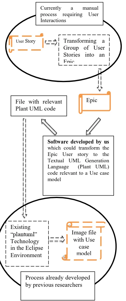
Fig. 14. Contextual diagram of the architecture of our prototype software
2.8.1 An Algorithm to generate Plant UML code
for
include
relationship in the Use Case
Model
Algorithm designed to generate Plant UML code for include relationship in the Use Case Model is given below.
Display Epics with corresponding User Stories.(Interactively)
Select Epics with identical or similar „I want’ clauses in user stories. (Interactively, semi-automatic)
Identify the include Use Cases that can be shared (re used)
Identify the include relationships
Generate the Plant UML code as in Figure 8.
Generate Plant UML Use case model with include relationship.
2.8.2 An Algorithm to generate Plant UML code
for
extend
relationship in the Use Case Model
Algorithm designed to generate Plant UML code for extend relationship in the Use Case Model is given below.
Display Epics with corresponding User Stories.(Interactively)
Select Epics with conditional or optional „So that’ clauses. (with words „may‟, „can‟, „could‟,‟sometimes‟, „either‟ etc.)
Identify the „Extend‟ use cases that are optional. Generate the Plant UML code as in Figure 10. Generate Plant UML Use case model with extend
relationship.
2.8.3 Algorithm to generate Plant UML code for
generalization
relationship in the Use Case
Model
•
Display Epics derived from User Stories. (Interactively)•
Select Epics with „kind of‟ or „is a‟ relationship.•
Generate the Plant UML code as in Figure 12.•
Generate Plant UML Use case model with inheritance or generalization relationship.•
2.8.4 Important blocks of the Java code for the
prototype
Important blocks of the actual Java code used in the Prototype is given below.
// Block which writes the (epic to use case model) transformed code into a text file
if(e.target.equals(bWriteToUMLFile)){ try {
BufferedWriter out = new BufferedWriter(new
FileWriter("D:\\JTest\\7_OUTPUTS\\UseCase_PHRASE_3\\" +tfUMLFileName.getText()+".uml"));
out.write("@startuml"); Image file
with Use case model Existing
“plantuml” Technology in the Eclipse Environment
User Story
Software developed by us which could transform the Epic User story to the Textual UML Generation Language (Plant UML) code relevant to a Use case model
Epic Transforming a Group of User Stories into an Epic
File with relevant Plant UML code
Process already developed by previous researchers
out.newLine();
out.write(taUMLText.getText()); out.newLine();
out.write("@enduml"); out.close();
// Block which writes the transformed (epic to use case model) code into text area
if(e.target.equals(bMakeUsecase)){ String optn;
optn =
chUsecaseType.getSelectedItem();
// Sub-block which transforms role and action into uml artifacts in plantuml code
if(optn=="Main"){
StrTextArea = StrTextArea + tfRole.getText() + " --> " + "(" + tfAction.getText() + ")";
taUMLText.setText(StrTextArea); }
3. DISCUSSION AND CONCLUSION
Prototype of the software was designed to transform Roles and Goals / Desires of Epics into Actors and Use Cases of Use Case models. The prototype of software to be developed is a proof of the validity of the concept developed and successfully tested by us (details of experiment given in [15]), that the Roles and Goals / Desires of Epics could be transformed into the Use Case Models.
The successful development of this software system which could transform User Stories to Use Case Models, would be a partial validation of our Ontology Based Framework, which was published in 2013 [7], [19]. At that stage, using this Ontology Based Framework as a basis, we could develop software which could not only transform User stories to Use case model, ERDs into Class diagrams - (a transformation which has already been conceptually validated by another experiment [20] – but also develop software which could perform other transformations such as lower level DFD to State Diagram and Sequence Diagram, Flow Chart to Activity Diagram, Entity Life History to State Diagram, and so on and so forth.
REFERENCES
[1] Fries T.P. (2006), “A Framework for Transforming Structured Analysis and Design Artifacts to UML”, The 24th annual conference on Design of communication. [2] Jilani A.A.A., Usman M., Nadeem A., Malik Z.I. and
Halim Z., (2011), “Comparative Study on DFD to UML Diagrams Transformations,” World of Computer Science and Information Technology Journal (WCSIT), pp, 10-16.
[3] Tilakaratna P., Rajapakse, J. (2011), Forward Engineering the Object Oriented Analysis and Design, The 5th Malaysian Conference in Software Engineering, 107-112.
[4] Tilakaratna P., Rajapakse J., (2012) “Ontological Framework for Object-Oriented Analysis and Design,” American Journal of Engineering and Applied Sciences 5 (3), 251-260.
[5] User Stories: An Agile Introduction [2016]
http://www.agilemodeling.com/artifacts/userStory.htm
[6] Use Cases, [2016],
https://en.wikipedia.org/wiki/Use_case
[7] R S Madanayake, G K A Dias, N D Kodikara, A Study of the Issues in the Transformation of Models between Different System Development Methodologies. SEARCC 2013, Sri Lanka; 2013 ISSN : ISSN 2279‐ 3895
[8] Ravi Madanayake, G K A Dias, N D Kodikara, “User Stories vs UML Use Cases in Modular Transformation”, International Journal of Scientific Engineering and Applied Science (IJSEAS) – Volume-3, Issue-1,Jan 2017 .
[9] Jacobson, I. and Spence I., (2010) “Using Use Cases on Agile Projects”, 10.
[10] Madanayake R S, G.K.A.Dias, N.D.Kodikara, “User Stories, Epics in Agile Methods Vs Use Case Models in UML”, Proceedings of the 72nd Annual Sessions, Sri Lanka Association for the Advancement of Science (SLASS) , ISSN: 1391-023X ,5 – 9 December, 2016 [11]Plant UML a free UML Diagramming tool.
https://en.wikipedia.org/wiki/PlantUML [Accessed Jan 2017].
[12]Tilakaratna, J.M.P.P., (2016) “Development and Evaluation of an Ontologically Complete and Clear Object-Oriented Conceptual Modelling Grammar”, PhD Thesis, 251-256.
[13]Hong Kong Institute of Vocational Education. (2016, February 3). [Online]. Available: https://www.visual-paradigm.com/support/documents/vpuserguide/2607/26 08/83675_overviewofue.html
[14]User stories vs use cases, agile development, Segue Technologies [2016]
http://www.seguetech.com/user-stories-vs-use-cases-pros-cons-agile-development/
[15]System Analysis and DESIGN METHODS, By Jeffrey L Whitten & Lonnie D Bentley ISBN 0-07-063417-3 ,7th Edition, 2007
[16]A Comparison of Use Cases and User Stories, Pankaj Kamthan, Systems and Software Engineering, Encyclopedia of Information Science and Technology, SBN 978-1-4666-5888-2, Third Edition, 2015
[17]How can we map use cases to stories?:
https://agilefaq.wordpress.com/2008/06/18/how-can-we-map-use-cases-to-stories/
[18]Plant UML in a Nutshell, http://plantuml.com/
University of Colombo School of Computing; In Proceedings of SLAAS Conference Dec 2013
[20]Madanayake, R S; Dias, G K A; Kodikara N D, “A Discovery of the Relevance of Eastern Four-valued (Catuskoti) Logic to Define Modular Transformations When There are Multiple Ways of Representing the Same Modular Transformation”, Online Journal of “Horizon.
AUTHOR PROFILES:
R. S. Madanayake received his BSc in Biological Science (2001) and his MSc in Information Technology (2009) both from the University of Colombo, Sri Lanka, and is currently reading for an MPhil at the University of Colombo, Sri Lanka. He has 03 fullpaper publications and 02 extended abstracts to his credit, all 04 of which are in the field of Modular Transformations involving Agile, UML and Structured Analysis and Design Techniques. His other interests include how Ontologies and Eastern Four-valued Logic fit into the field of Computer Science.
G. Kapila .A. Dias received his BSc in Physical Science (1982) from the University of Colombo, Sri Lanka, Postgraduate Diploma in Computer Studies from University of Essex,UK (1986), and MPhil in Computer Science from University of Wales,UK (1995). He is currently a Senior Lecturer at the University of Colombo School of Computing (UCSC). He is a member of the Computer Society of Sri Lanka, Sri Lanka Association for Advancement of Science (SLASS) and a member of the ACM the world‟s largest educational and scientific computing society. He received the winner award for his „Travel Meter‟ project in eSwarbhimani 2016, Sri Lanka under Culture & Tourism Category. He was a Member of the team which won the Bronze award under Education & Training category in NBQSA Sri Lanka-National Best Qualaity Software Award -Oct 2015 for K8-Flight Simulation project, NSF (National Science Foundation)Technology Award of Excellence 2016 –“COP Sayura: The three Dimensional Coastal Surveillance System for SLN High Command. He has more than 50 peer reviewed publications to his credit. His research interests are computer aided software engineering, multimedia for education, modeling and simulation, artificial neural networks and model driven engineering.
Nihal D. Kodikara is a Professor attached to the University of Colombo School of Computing (UCSC). His research interests include Image Processing, Computer Vision, Computer Graphics and Software Engineering. Prof. Kodikara obtained his B.Sc. from University of Colombo and M.Sc. and Ph.D. in Computer Science from the University of Manchester, U.K. He has received Colombo Plan Technical Award in 1986 for Ph.D. studies and Commonwealth Fellowship Award in 1997. He has over 35 years of teaching and research experience. He is presently the Head of the Modelling and Simulation
![Fig. 12. PlantUML code block which codes for Use Case Model which has generalization relationship [11]](https://thumb-us.123doks.com/thumbv2/123dok_us/1327457.1640916/7.612.74.249.507.568/fig-plantuml-block-codes-case-model-generalization-relationship.webp)