e-ISSN: 2278-7461, p-ISSN: 2319-6491
Volume 5, Issue 3 [February 2016] PP: 06-15
Improvement Of VLC Data Transmission System Using OWC
System Under Influence Of FLI
M.Sundararajan
1, R.Kousalyadevi
2,
1.
PG Student, Department of Electronics and Communication Engineering, PERI Institute of Technology, Chennai
2.Prof & Head, Department of Electronics and Communication Engineering, PERI Institute of Technology,
Chennai
Abstract: Light waves cannot pass through concrete or solid elements the advantage from an inherent safe broadcast of data in physical layer. Co-channel obstruction is an issue in radio waves and a cause of noise. Idea of divert impedance is inexistent in VLC. Still an encompassing light source presents noise in framework. We can say that OWC network are need of great importance and will give broadband data to settled and mobile clients in little in-door region in calculation to its sending in outside environment. OWC innovation is a standout amongst the most encouraging option plans for tending to the 'last mile' bottleneck in developing broadband access markets OWC offers an adaptable systems administration arrangement that conveys the genuinely broadband administrations.
Keywords: OWC, VLC, FSL, AWGN channel
I.
INTRODUCTION
(OWC) Optical Wireless Communication system depends on optical radiations to pass on data with free space, with wavelengths extending from infrared (IR) to ultraviolet (UV) including noticeable light spectrum [3]. The key outline difficulties to accomplishing fast OWS transmission inside branch from free space loss (FSL), ambient light noise, and/or interference, and multipath dispersion causing inter symbol interference. The induce signal corruption is genuinely biased by connection arrangement. The execution of the OOK, PPM & DPIM in vicinity of FLI, ISI is researched to enhance the connection execution conceivable relief systems utilizing high-pass filtering, equalization, wavelet and neural network.
OWC alludes to information transmission utilizing Infrared (IR), Wireless Communication (IrWC), ultraviolet remote correspondence, VLC and Free Space Optics (FSO) and as opposed to radio waves. Optical wireless undoubtedly appreciates specific points of interest over radio waves are purpose behind a well known region of exploration.
II.
DATA TRANSMISSION-VLC
In optical source two techniques are normally utilized for era of white light. Blending determined amounts of RGB shading that produces white light. The significant purpose behind not utilizing RGB LEDs as a part of general lighting is to intersections that deliver and the green light are not as proficient as the intersection that creates blue light. Effectiveness of the blue light will be around 80% while it will be around 60% & 30% for red and green light individually. Moreover this strategy had specific bundling and electronic complexity which make it a fewer positive system. Most alluring strategy is called as phosphor based white LED. HBLEDs create white light to do without a doubt deliver a blue light. Be that as it may, the phosphor (i.e. transcendently yellow) just changes over piece of blue light. The changed over and non-changed over parts are blended to acquire craved shade of white.
In VLC, with respect to exploring two essential properties of LED i.e. luminous intensity and transmitted optical power
Scientifically, we will state iridescent power I by eq. (2.1)
Where energy flux , standard luminosity curve and maximum visibility . For a source with
PTW LEDs emits wideband visible light is extend above the whole visible spectrum (appeared in Fig 2.1) and transmits optical force is portrayed by the eq. (2.3)
Here and is sensitive curve of PD.
Progressive implicit preferences of LED i.e. quick exchanging, low driving voltage similarity among computerized innovation can develop programming controlled shrewd radiant and communication system [25]. Communication system exists as tweak transfer speed is constrained and drowsy reaction of yellow phosphors changing over blue to yellow. Though equalization, filtering can upgrade data rate. Wide band of phosphors topped white LED results in multipath scattering which is like a test. Multipath enables PDP by numerous optical source is demonstrated by eq.2.4
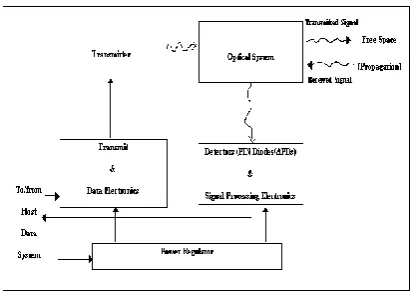
Block diagram of a commonplace optical receiver is appeared in Fig. 2.1.
Fig 2.1 Block diagram of an optical receiver.
Indoor VLC communication system, encompassing light sources likewise fall in the obvious range. Optical filtering is done to limit down the band. Filtering signal is then sustained to the photo detectors which change over the optical signal into electrical sign as photo current. Two sorts of photo detectors can be utilized. First the photo diode (PD) and next is image sensor. photodiode is the modest arrangement still for complex programs, picture sensors are utilized. Photocurrent is then increased utilizing trans-impedance enhancers and after that evening out is finished information rate change can be examined in future segment. The vicinity of DC sign made by backdrop noise will be calculated by utilizing high pass channels. The signal and ambient light prompted shot noise can be demonstrated as eq. 2.5
Where σ is the charge on electron, and Ir are signal and
Irambient ambient light current in the photo detector separately and q is the noise bandwidth factor. Optical power
received may be displayed as eq. (2.6)
where A is the physical region of detector in PD, Separation between transmitter and receiver , angle of
incidence ψ, angle of irradiance υ, optical filter gain Ts(ψ), and optical concentrator gain g(ψ). ΨC signifies width of field of vision at a receiver.
2.3. TECHNIQUES TO IMPROVE DATA RATE
There are numerous approaches to enhance data rate in VLC framework. Optical separating, pre and post evening out, complex tweak systems and optical MIMO are usually utilized procedures.
and computerized strategies can be utilized for balance. Simple circuit adjustment is more fitting with On-Off Keying plans where OFDM plan utilizes evening out as a part of computerized space. Balance utilizing a solitary LED and cluster of LEDs has been accounted for. A fruitful 80Mbps short range information join has been set up. Utilization of numerous resounding equalizers can promote improve the information rate by 10 times as proposed. 25 times more data transfer capacity i.e.. 50MHz has been exhibited in that 100Mbps NRZ Keying plans when OFDM plan utilizes adjustment as a part of advanced space. RC equalizer is utilized which recurrence reaction has given by eq. 2.8
Versatile adjustment will be utilized to conquer ISI as planned. Optical Multi-Info Multi-Yield (MIMO) meant for accomplishing higher information rate is a hot region of examination. Solitary LED had little transfer speed however numerous LEDs will make a critical data transfer capacity. Challenge here is to accurately adjust the indicator and a portable beneficiary. MIMO gives the chance to do.
2.4. INDOOR OPTICAL WIRELESS SYSTEMS 2.4.1. System Overview
Since 1970's, optical remote (IR) innovation to rapid indoor information interchanges; that is still a dynamic range of exploration. Additionally, in the previous quite a long while, broad exertion has been dedicated to comprehension and executing optical remote procedure for long separation between satellite frameworks (open air applications). Yet, the internal applications are main thrust behind optical remote. The principal indoor optical remote framework was created in 1979. Thus framework utilized infrared radiation which was spread in all bearings. Such frameworks are known as diffused infrared frameworks. From that point forward a few items utilizing IR radiation have been effectively marketed. The progression of economical opto-electronic gadgets, for example, LEDs / LDs, p-characteristic n (PIN) photograph diodes, torrential slide photograph diodes (APDs) and different optical parts, had brought about the change of these frameworks. Indoor optical remote frameworks had been utilized as a part of numerous applications in the previous couple of years, going from straightforward remote control in home to many intricate remote neighborhoods. Numerous different applications are imagined for future, incorporating information organizing in indoor environment and conveyance of broadband mixed media administrations to versatile clients inside such a situation together with general availability to base systems. A few organizations have presented information correspondence items utilizing optical remote innovation and numerous other PC correspondence items are entering the business sector.
Figure 2.2 A Block Diagram of A Basic Optical Wireless Terminal
photodiodes. The optical remote framework utilizes IR innovation as a part of which connections depend on power balance and direct recognition (IM/DD) of optical bearer. Power regulation is carried by shifting drive current of LED / LD. Straight identification is performed by PIN photograph diodes or APDs which deliver an electric current relative to episode optical power.
III.
METHODOLOGY
Effect of FLI without electrical high-pass filtering
The various types of modulation plans with OOK, PPM and DPIM at different data rates, and that are mutilated by the incorporation of FLI No type of filtering or other repaying systems will be used to evacuate the deterrent. Two key execution pointers as portrayed underneath:
Normalized optical power requirement (NOPR):
The NOPR of a structure is discovered by normalizing optical force necessary to finish the exact bit/slot blunder likelihood ξ in the meddling channel with that of OOK framework at 1 Mbps in a flawless AWGN channel without check,
Optical power penalty(OPP):
OPP system is computed by normalizing optical power essential to accomplish error chance of ξ in interfering channel by means of exact AWGN channel exclusive of obstruction.
IV.
MATCHED FILTER RECEIVER
In block diagram of OWC system employs a matched filter receiver is appeared below. The decoder and encoder should be included at receiver and transmitter for modulation plans apart from OOK. The transmitter filter had a unit-amplitude rectangular impulse response p(t), with time period of single bit, Tb .
Fig.3.1. Block diagram of OWC system under influence of FLI
The response of transmitter filter is obtained by peak-detected signal photocurrent 2RPavg, where R is photo detector responsively and is average received power. The fluorescent light-induced photocurrent,
, is combined to signal, with signal to independent shot noise n(t) and is demonstrated as white &
Gaussian, with double sided power spectral density (PSD) No/2 = qIB.IB is average photocurrent generated by back ground light, will be occupied as 202 μA., the HPF be unwanted and the discovered signal is accepted through r(t), which is corresponding to p(t). The response is sampled at every bit period, and 0 or 1 is assigned depending on whether signal is above or beneath the threshold level at sampling instant. The threshold level is
maintained to its optimum value i.e.
3.3 EFFECT OF BASELINE WANDER WITHOUT FLI
to defeat the impact of standard meander is researched. Its output to a solitary rectangular pulse of amplitude A
and period of time τ might be communicated as
Where filter time constant RC = 1/2πfc. Thus, single bit sequence A1 A2 … .A, where A1 n ∈ {0, 1}, output of first-order RC HPF toward the end of nth bit might is communicated as
The effect of baseline wander on execution of baseband modulation with no FLI is analyzed.
3.4 EFFECT OF FLI WITH ELECTRICAL HIGH PASS FILTERING
An electrical HPF can lessen impacts of FLI, whether it is actualized in analog or digital space. The decision of cut-on frequency is an exchange off among degree of FLI dismissal and seriousness of pattern presented by HPF and attenuation of interfering signal; ideal decision being what reduces general power punishment. When fc is a serious parameter, other channel attributes, for example, the stop band attenuation and the move off are additionally liable to affect the execution that might deliver varieties in the ideal fc Given that the ideal fc change data rate, an arrangement would be to reenact a framework over all conceived data rates and fc to decide the right slice on recurrence to utilize. That is clearly not exactly down to earth and tedious; a trade off technique being to pick a predetermined amount of data rates and a scope of fc for an offered channel to decide as near the ideal as could be expected under the circumstances In this segment, the ideal fc for HPF which minimize general power penalty, is evaluated utilizing a strategy that consolidates the investigation completed in the past two segments. With the ideal cut-on frequencies optical force necessities are ascertained, and adequacy of HPF as a method for moderating impact of FLI is surveyed. To decide ideal fc, is embraced with the consideration of mutually FLI signal and HPF. The inspected yield because of FLI signal in wake of going through coordinated channel and HPF is given by
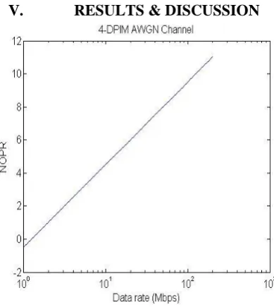
V.
RESULTS & DISCUSSION
Fig.4.2. 8-DPIM AWGN Channel
Fig.4.3. 16-DPIM AWGN Channel
Fig.4.5. 8-DPIM in FLI Channel
Fig.4.6. 16-DPIM in FLI Channel
Fig.4.7. Optical ideal power on NOPR
is under 1dB for 16PPM and 2dB for 4PPM. OPP is minimum for 16PPM furthermore diminishes with data rate for every bit resolution. OPP at 200Mbps is ~3dB for 16PPM and right around 0.5dB higher for 8PPM and a further ~0.5 dB penalty happens for 4PPM. For PPM system with low PSD at or close DC, OPP is altogether lower when contrasted with the OOK for all data rates. Though, delicate choices disentangling offer a important resistance to FLI. In detail, NOPR for PPM with obstruction and without obstruction are verging on indistinguishable for data rates>20 Mbps. The execution change at high information rate is because of lessened variety of FLI signal above length of time of single image (take note of that delicate choice is completed taking into account the related amplitude of slot with a symbol). In delicate location, it is estimations of FLI tests in respect to different examples inside of the same image which are essential; instead of the outright values. This prompts a lower likelihood of image mistake, subsequently diminishing the force punishment [1]. The past cases for OOK and PPM plans by HDD, a noteworthy power punishment happens because of FLI for the DPIM regulation plan also and little variety in NOPR for data rates.
Fig.4.8. Effect of HPF and Baseline wonder in OOK-NRZ signal
To delineate the impact of baseline wander, suppose OOK–NRZ signal by rectangular pulseshape as appeared in Fig 4.8a. The HPF response gout(t) with cut-off frequency of 0.05 times bit rate will be equivalent to baseline wander be appeared in Fig 4.8b and c, individually. Notice the variety in amplitude for 0 and 1 level in Fig 4.8b. The normal worth (i.e. midpoint among the low and high levels) of high-pass sign indicated change in time (see Figure 4. 8c), and its variety that changes the baseline wander.
Fig.4.10.Histogram of matched filter output for OOK with
Fig.4.11.Histogram of matched filter response for OOK with
The histogram plot of coordinated channel yield with HPF and without HPF for normalized cut on frequency of 10−1, 10−2 and 10-3. The solid line in focal point of plot demonstrates an estimation of 0, i.e. no distinction in the middle of expected and genuine coordinated filter outputs, which would be the situation without standard meander The expansion in the fluctuation of the likelihood dispersion as fc/Rb increments from 10−3 to 10−1 is apparent from the figure. For moderately low estimations of fc/Rb the HPF drive reaction traverses numerous bit periods. Therefore, ISI presented by HPF is involved weighted aggregate of numerous free and indistinguishably dispersed (i d) twofold arbitrary variables Therefore, as a consequence of as far as possible hypothesis, the circulation can be exactly as Gaussian [3], as affirmed by general state of the histograms[13] utilized this Gaussian exactly to create shut structure terms for likelihood of mistake because of baseline wander and Gaussian noise for OOK also expanded this work, utilizing nontraditional Gauss quadrature rules to decide chance of error, as opposed to expecting a Gaussian distribution.
The equivalent filter receiver by a settled threshold level discovery talked about in past area obviously demonstrated to optical power penalty increment increased by station delay spread and force punishment is high for adjustment plans with shorter pulse span. Thus execution requirements of a straightforward edge based recipient in an noisy multipath channel, to discover option relief plan keeping in mind the end goal to diminish the corrupting impacts of ISI & noise. Most strategies utilized in spread indoor OWC systems are actualized in electrical space and are obtained from the more settled RF innovations.
VI.
CONCLUSION
filter is to enhance SNR by dismissing high-frequency components are not connected with accepted signal. Such filter be Matched filter, which is ideal filter for digital communication into AWGN channel.
Thus ideal method for making so as to execute this plan is the normalized gain output of receiver channel Hr( f) indistinguishable to amplitude spectrum of pulse Gr( f). This understood strategy is copiously archived in the writing and can without much of a stretch be estimated in system and simulation by basic incorporate and unload circuitry; as average power of noise is 0, circuitry expands SNR similarly. The vicinity of multipath induced ISI will seriously influence the execution of a coordinated separated based collector on the off chance that it is coordinated to the transmitter channel and the channel contortion is not thought about; in this manner, coordinating will never again be exact.
REFERENCES
[1]. D. O'Brien, G. Parry, and P. Stavrinou,(2007) "Optical hotspots speed up wireless communication," Nature Photonics, vol. 1, pp. 245-247.
[2]. Z.Ghassemlooy, W.Ropoola and S. Rajbhandari (2013), ’Optical Communications: System and Channel modelling with MatLab’, CRC Press, 2013.
[3]. Hany Elgala, Raed Mesheh and Harald Haas (2011),’Indoor Optical Wireless Communications: Potential and State-of-the-Art’, IEEE Communication Magazine, September 2011, pp. 56-62.
[4]. Pakistan Telecommunication Authority (PTA) Consultation Papers of Radio Frequency Hazards http://www.pta.gov.pk/media/rfh.pdf
[5]. Federal Communication Commission http://www.fcc.gov/
[6]. Muhammad Saadi, Paramin Sangwongngam, et. al., "Global Efforts in Realizing Visible Light Communication Systems and its Comparison with other Short Range Wireless Communication Networks”, NTBC end year conference 2011, December 15-16, 2011.
[7]. K. Daniels, K. Chandra, Co-Channel Interference, Mobile Computing and Communications Review, Vol. 1, No. 2.
[8]. Mohsen Kavehrad, “Broadband Room Service by Light”, Scientific American, July 2007. [9]. David J. T. Heatley, “Optical Wireless: The Story so far”, IEEE Communication Magzine, 1998.
[10]. Olivier Bouchet, Pascal Besnard, “Indoor Free Space Optic: A new prototype, realization and evaluation”, Collaborative project Techim@ges – Cluster Media & Networks – Britanny, France.
[11]. Kaiyun Cui, Gang Chen, “Line-of-sight Visible Light Communication System Design and Demonstration”, CSNDSP, pp. 621-625, 2010.
[12]. Kwonhyung Lee, John. Barry, “Indoor Channel Characteristics for Visible Light Communications”, IEEE Communications Letters, 2011.
[13]. Jae Kyun Kwon, “Inverse Source Coding for Dimming in Visible Light Communications Using NRZ-OOK on Reliable Links”, IEEE Photonics Technology Letters, Vol. 22, 2010.
[14]. Mohsen Kavehrad, “Sustainable Energy-Efficient Wireless Applications Using Light”, IEEE Communications Magazine, 2010.
[15]. Toshihiko Komine, “Fundamental Analysis for Visible-Light Communication System using LED Lights”, IEEE Transactions on Consumer Electronics, Vol. 50, No. 1, Feb. 2004.
[16]. S. Jivkova, M. Kavehrad, “Transceiver Design Concept for Cellular and Multispot Diffusing Regimes of Transmission”, EURASIP Journal on Applied Signal Processing, Vol. 1, pp. 30-38, 2005