Monitoring and Control of the Greenhouse
Using Remote Control Device and IoT
Edin Mujčić
1, Una Drakulić
21,2 Faculty of Technical Engineering Bihać
University of Bihać, City, Bihać, B&H
Abstract- The production in protected areas requires a lot of work to create and to maintain the microclimatic conditions for plants to grow healthy and fast. To solve this problem automated systems are used. This paper proposes an automated system for controlling and monitoring microclimate conditions in a greenhouse. This system operates automatically and the user monitors its operation and if necessary remotely changes the individual system parameters. A remote control device, that is designed and programmed, is working on an independent WiFi network. A remote control device has been designed to change values to essential parameters. Essential parameter for plant growth are temperature, air quality, soil moisture light and etc. All the essential parameters for the growth of plants inside the greenhouse are also sent to t he cloud using a local WiFi network. For easy access to this information, a website has also been created. The user is also enabled to change the microclimatic conditions inside the greenhouse through the website and through the cloud.
Keywords – ATMega2560 microcontroller, Cloud, Greenhouse, IoT, NodeMCU (ESP8266 WiFi module), ThingSpeak
I. INTRODUCTION
Production in open fields is becoming increasingly difficult due to unstable weather with sudden temperature fluctuations, heavy droughts and heavy rainfall accompanied by hail [1]. As a result, there is a growing need to grow plants in greenhouses. In B&H, greenhouse production is still in the development phase, but it can be noticed that more people are expressing the need for fresh fruits and vegetables and their availability throughout the year. The greenhouse can be automated and thus relieve the user of the day-to-day obligations for maintaining optimal conditions in the greenhouse. In an automated greenhouse, the user can, regardless of their location, through a computer or other smart device, control the brightness, temperature, soil humidity, and air quality [2]. LED lighting is used as an alternative light source because different wavelengths of light produce different levels of energy that plants absorb[3][4]. In this paper is proposed the design and implementation of the greenhouse using a remote control device and IoT. In this paper is used the Arduino open-source platform to program the ATMega2560 microcontroller. The Arduino is a microcontroller board with an Atmel microcontroller and additional parts needed to operate the microcontroller and external connectors for easy connection of external elements [5]. Communication was performed using a wireless WiFi network. Like every communication network, WiFi also involves transmitter (Wireless Router/Hotspot) and receiver which can be any Wifi-enabled device like laptop, mobile, tablet, etc. WiFi network is convenient, flexible, and easy to use [6]. All of the data that the sensors read in the greenhouse model, which reflect the current state, will be able to be monitored by the user via the cloud. For this purpose, the ThingSpeak is used. ThingSpeak is an open-source Internet of Things application and API to store and retrieve data from things using the HTTP and MQTT protocol over the WiFi or via a LAN. All data from the cloud are pulled to the Web page. This Web page is designed for easier user interaction with the projected system. The Web page is enabled to set desired values that will be sent to the projected system. Also, the remote control device is designed and programmed. This remote control device receives all of the data that the sensors read in the greenhouse and display them. The user can set desired values for the parameters and those will be applied in the greenhouse system. Also, an experimental work analysis of the proposed system is performed.
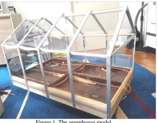
II. IMPLEMENTATION AND DESIGN OF THE PROPOSED GREENHOUSE SYSTEM
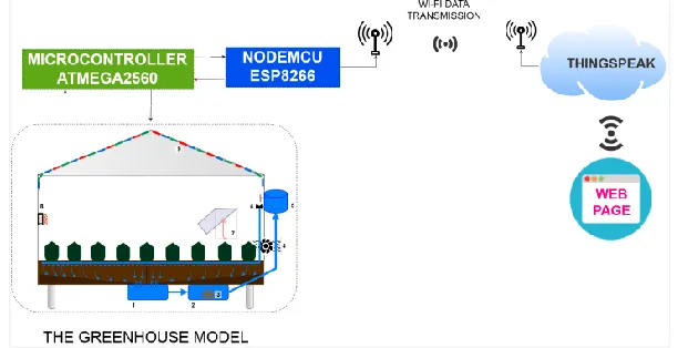
Figure 1. The greenhouse model
The functional block diagram of the proposed system is shown in Figure 2.
Figure 2. The functional block diagram of the proposed system
From Figure 2 we can see that the proposed system consists of several subsystems. These subsystems are: 1. Watering subsystem,
2. Lighting subsystem,
3. Temperature control and air quality subsystem,
4. Remote monitoring and control using remote control device subsystem, 5. Remote monitoring and control using IoT subsystem.
2.1. The watering subsystem
Figure 3. The functional block diagram for the watering subsystem
In Figure 4 the block diagram of the watering subsystem with the indicated electrical components is shown. By using the remote control device or using the designed web page, the user inputs the desired soil moisture and the proposed system maintains the set values for soil moisture at that level. Feedback on the real soil moisture is sent to the cloud and the created web page and to the remote control device. In this way, the user has at all times the true values of soil moisture in individual parts of the greenhouse.
Figure 4. The functional block diagram for the watering subsystem with components
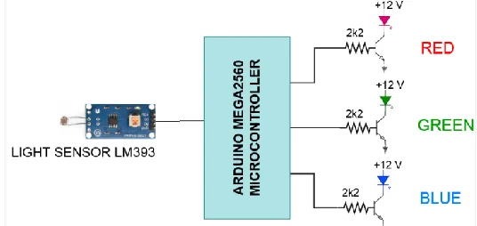
2.2. The lighting subsystem
plants. Blue light helps to stimulate vegetative growth and leaves growth. Red light combined with blue light allows the early flowering of plants. Knowing that different colors of light can affect how a plant grows people can make the most from plants.
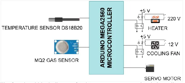
2.3. The temperature control and air quality subsystem
For each plant, there is an optimum temperature range for which maximum results are obtained. However, in many cases, we cannot achieve this without high energy consumption. In this case, the cost-effectiveness of such a subsystem is highly questionable.
In our case (see Figure 6), the temperature control is performed in a way that the user sets the desired temperature. The system heats up on the basis of the thermal values. If the desired temperature is higher than the real temperature the window on the greenhouse model is open and the cooling fan is turned on. The air quality in the greenhouse model is very important for the growth of plants. In daylight, plants use carbon dioxide for the process of photosynthesis. When daylight disappears, activation of process where plants take in oxygen that they use to break down sugar into energy, releasing carbon dioxide. In the proposed greenhouse model this is solved using the MQ2 gas sensor.
Figure 6. The functional block diagram for the temperature control and air quality subsystem
If the MQ2 sensor reads lower value then the value which the user had set for air quality, then the cooling fan and the servo motor will turn on. Servo motor opens the window. After a while, when the value for air quality is in the desired range the cooling fan and servo motor will turn off.
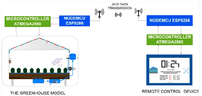
2.4. The subsystem for remote monitoring and control using remote control device
Modern trends in today's world is connections as many devices and as many systems as possible to the Internet. In this way, the systems can be remotely monitored, controlled, analyzed or adjusted by the important parameters of the system.
Figure 7. The functional block diagram for the remote monitoring and control subsystem
The proposed system, the system for remote monitoring and control of microclimate conditions in the greenhouse model is connected wirelessly, using the NodeMCU, to the global Internet. NodeMCU is an open source Lua based firmware for the ESP8266 WiFi SOC [7]. The collected data is saved to the cloud (ThingSpeak platform). Using the Webpage (designed for the proposed system), the collected data in the cloud is passed to the users. On the other side, the user is allowed to change the important parameters in the greenhouse model using the designed web page. The parameters that the user enter are sent from the web page to the cloud, and from the cloud to the designed system for remote monitoring and control of microclimate conditions in the greenhouse model. This allows the user to monitor and control the proposed system from any location in the world that has Internet access. In the Figure 8 is shown the remote control device. The remote controle allows the user to be away from the greenhouse system. The user has access to all relevant data and can set the desired parameters in the greenhouse. The remote controller is shown in Figure 8.
Figure 8. The appearance of the emote control device
In Figure 8 is shown the remote controller device. The main window is shown in 8.a., the password window is shown in 8.b. and in 8.c. is shown the menu window.
Figure 9. The appearance of the menu window
Figure 10. The functional block diagram for the remote monitoring and control subsystem
This system is realized using Node MCU esp8266 module which is connected to Arduino board with ATMega2560 microcontroller in the greenhouse system. Node MCU esp8266 model, using a Wi-Fi wireless network, sends received data to the cloud. For this purpose is used the ThingSpeak platform. Also, we have designed a Web page that pulls all data from the ThingSpeak platform. On the Web page are shown all parameters with received values in real-time with the possibility to add desired value to a specific parameter. In figure 10 is shown the functional block diagram for IoT subsystem.
This subsystem enables data monitoring in the greenhouse system for a longer period of time as well as an overview of all relevant data from any location in the world that has access to the Internet. Because this subsystem is based on the use of wireless Wi-Fi network, it is important that there are no physical gaps that would significantly reduce the power of the Wi-Fi signal.
III. EXPERIMENTAL WORK ANALYSIS FOR THE PROPOSED GREENHOUSE SYSTEM
For experimental analysis, we changed the desired parameters and monitored the response of the projected system. First, we set the desired temperature to 19 degrees on the remote control device. The current temperature in the greenhouse model is 22 degrees. After a few seconds the cooling fan is turning on and the servo motor opens the window. After a short time, the temperature in the greenhouse model dropped to 19 degrees. In case the projected system cannot reach the desired temperature, because it doesn't have an artificial cooling system installed, the projected system will turn off the cooling fan and close the window after reaching the minimum possible optimal temperature and will continue to maintain that temperature. The finished appearance of the proposed greenhouse system is shown in Figure 11.
If we set the desired temperature to 25 degrees. The projected system turns off the cooling fan and closes the window, and turns the heater on. When the desired temperature is reached, the heater turns off and the system maintains the given temperature.
Figure 11. a) Hardware (bottom side) of the greenhouse model b) The finished appearance of the proposed greenhouse system c) The remote control device
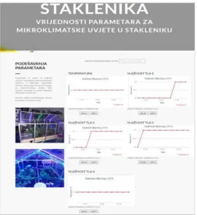
On the Figure 12 is shown the appearance of designed ThingSpeak channel with obtained data and on Figure 13 is shown the appearance of designed Web page with obtained data.
Figure 13. The appearance of designed Web page with obtained data
IV.CONCLUSION
Based on experimental analyses we can conclude that the proposed system is working properly. Also, we can conclude the projected system for remote monitoring and control microclimatic conditions in the greenhouse model with minimal change can use for remote monitoring and control in the real greenhouses.
V. REFERENCES
[1] Jemma G., Richard B., Eleanor B., Robin C., Joanne C., Kate W. and Andrew W.: Implications of climate change for agricultural productivity in the early twenty first century, Philos Trans R Soc Lond B Biol Sci. 2010 Sep 27. The Royal Society Publishing
[2] Una Drakulić and Edin Mujčić: “Remote Monitoring and Control System for Greenhouse Based on IoT”, Advanced Technologies, Systems, and Applications IV - Proceedings of the International Symposium on Innovative and Interdisciplinary Applications of Advanced Technologies (Iat 2019), pages: 481:496, Expected publication: October 2nd 2019 by Springer
[3] Edin Mujčić, Una Drakulić and Merisa Škrgić: Advertising LED System Using PIC18F4550 Microcontroller and LED Lighting, International Symposium on Innovative and Interdisciplinary Applications of Advanced Technologies IAT, Neum, B&H, 2016
[4] Chen, T.Y., Chu, C.C., Henneberry, T.J., Umeda, K.: Monitoring and trapping insects on poinsettia with yellow sticky card traps equipped with light-emitting diodes, HortTechnology 14 (3), 2004, p.337-341
[5] Edin Mujčić, Una Drakulić: Upotreba Android operativnog sistema i mikrokontrolera ATMega2560 za upravljanje 3D LED matričnim displejem, 11th International Scientific Conference on Production Engineering, Development and modernization of production, RIM2017 [6] Haishen Peng: WiFi network information security analysis research, 2012 2nd International Conference on Consumer Electronics,
Communications and Networks CECNet, Yichang, China
[7] Suvankar Barai, Debajyoti Biswas, Buddhadeb Sau: Estimate distance measurement using NodeMCU ESP8266 based on RSSI technique, 2017 IEEE Conference on Antenna Measurements & Applications CAMA, Tsukuba, Japan