IMPLEMENTATION OF MOVING OBJECT DETECTION USING
ANGLE CHANGE METHOD
Neha Garg1 & Preeti2
1.INTRODUCTION
There has been a significant development in the area of digital image and video technology in the last twenty years. Because of the ever improving computer technology and high resolution cameras, the interest in video surveillance and similar computer vision technologies has soared. Tracking and detecting motion of objects in a video sequence is one of the most important tasks of the emerging computer vision technologies.
Video surveillance has become a very popular mode of monitoring, especially in secure or restricted access areas. Sensors which detect the moving objects are used in almost all video surveillance applications. By using the estimated motion, objects can be segmented. Segmentation of moving objects can be beneficial to segregate regions of interest from the background. For example, if a security/surveillance system is being used to segment a particular object (or person) in a crowd, segmentation techniques can be very useful in such cases.
Several camera and web camera manufacturers are using the concept of video surveillance by motion detectors. These motion detectors help users to keep a watchful eye on any area of interest in their absence. The motion detector triggers a recording whenever it senses any motion. The recording automatically stops when the motion goes below a certain level (depending on the sensitivity of the camera). The recorded motion can be viewed in the form of image snapshots or video files (each with a time and date stamp indicating the start of motion detection). There are so many algorithms are available for moving object detection but most of them work with background models and colour techniques. Background model and colour techniques have some problems. The main focus of this thesis is to detection of moving objects in video surveillance using angle change method.
Motion Detection
This research project includes two main steps used to detect the moving objects in a video sequence. The first step is to estimate the motion in a video sequence or a frame. This step is important to determine the object(s) that should be segregated from the frame under consideration. The second step is to segment the moving objects (determined from the first step) from the stationary object(s) or background in the considered frame/image. The next two sections present the basic concepts of estimation of motion and the subsequent segmentation of the moving objects from a frame/video image.
Estimation of Motion
In simple terms, motion can be defined as displacement of moving objects between the frames under consideration. The motion estimation models that have been proposed till now are based on measuring this displacement between objects. Currently existing motion detection and measurement techniques usually employ at least two frames of video images from a video sequence. The motion is usually computed by comparing any two consecutive frames (from a video sequence) at a given time. Some of the most widely used methods are:
• Optical Flow Method • Motion Vector Estimation • Image Subtraction
1 Department of Computer Science Engineering, Gurukul Vidyapeeth Institute of Engineering and Technology, Banur, Punjab,
India
2 Department of Computer Science Engineering, Gurukul Vidyapeeth Institute of Engineering and Technology, Banur, Punjab,
India
DOI: http://dx.doi.org/10.21172/1.91.04
e-ISSN:2278-621X
Abstract-This paper conclude the work in terms of input and output parameter that has been considered while detecting the moving object in video surveillance. It also provides with a look up of our work area. This paper presents a discussion of various techniques like Background subtraction, Block matching, Frame differencing, Optical Flow used in motion detection and also include the comparative analysis of two algorithms first is Colour method(Space vector difference method) and second is angle change method.
Segmentation of Moving Objects
Segmentation of moving objects is done in order to separate the moving objects from their stationary background. Image segmentation has found wide applications in the field of medical and biomedical imaging. Various methods have been proposed and tested for segmentation of moving objects. Some of these methods [1] can be broadly classified on the basis of the principle as:
• Clustering • Edge Detection • Histogram-Based • Level Set • Model Based • Thresholding
• Neural Networks and other Artificial Intelligence Based Techniques
2.LITERATUREREVIEW
Zhiqiang Hou, Chongzhao Han (2001) purposed a background reconstruction algorithm based on pixel intensity classification is presented. Assumption of this method is background pixel intensity appears in image sequence with the maximum probability is adopted. The pixel intensity values are classified based on the calculated pixel intensity difference between Inter-frames. Finally the intensity value with the maximum frequency is selected as the background pixel intensity value. In proposed algorithm, the pre-training of no-moving object in background and the models of background and target aren’t needed, and only one parameter is adjusted. Simulation results to real video surveillance sequences show that background can be reconstructed correctly, so target can be extracted perfectly and tracked successfully [2].
Masayuki Yokoyama, TomasoPoggio (2005) [3] purposed a fast and robust approach to the detection and tracking of moving objects. This method is based on using lines computed by a gradient-based optical flow and an edge detector. While it is known among researchers that gradient based optical flow and edges are well matched for accurate computation of velocity, not much attention is paid to creating systems for detecting and tracking objects using this feature. In this method, extracted edges by using optical flow and the edge detector are restored as lines, and background lines of the previous frame are subtracted. Contours of objects are obtained by using snakes to clustered lines. Detected objects are tracked, and each tracked object has a state for handling occlusion and interference. The experimental results on outdoor-scenes show fast and robust performance of our method.
Aurelie Bugeau, Patrick Perez (2007) [4] proposed a new method for direct detection and segmentation of fore-ground moving objects in the absence of such slowly changed background constraints. First, groups of pixels having similar motion and photometric features are extracted. For this step only a sub-grid of image pixels is used to reduce computational cost and improve robustness to noise. We introduce the use of p-value to validate optical flow estimates and of automatic bandwidth selection in the mean shift clustering algorithm. In a second stage, segmentation of the object associated to a given cluster is performed in a MAP/MRF framework. Our method is able to handle moving camera and several different motions in the background. Experiments on challenging sequences show the performance of the proposed method and its utility for video analysis in complex scenes.
ShireenY.Elhabian (2008) purposed a method by survey many existing schemes in the literature of background removal, surveying the common pre-processing algorithms used in different situations, presenting different background models, and the most commonly used ways to update such models and how they can be initialized. He also survey how to measure the performance of any moving object detection algorithm, whether the ground truth data is available or not, presenting performance metrics commonly used in both cases [5].
Xiaoshi zheng, Yanling Zhao (2009) [6] purposed frame difference algorithms are suitable for these applications. First of all, an automatic threshold calculation method was proposed according to statistic information to obtain moving pixels of video frames. Then moving regions can be formed by morphological operations. At last, the nearest distance of two regions was proposed and it was satisfying for region combination. The proposed algorithm is automatic and efficient in intelligent surveillance applications and A.A. Shafie purposed [7] a technique moving object detection using optical flow. Optical flow cannot be computed locally, since only one independent measurement is available from the image sequence at a point, while the flow velocity has two components. A second constraint is needed. The method used for finding the optical flow in this project is assuming that the apparent velocity of the brightness pattern varies smoothly almost everywhere in the image. This technique is later used in developing software for motion detection which has the capability to carry out four types of motion detection. Many objects such as vehicles and human from video streams can be recognized by applying optical flow technique.
3. ALGORITHM OF ANGLE CHANGE METHOD
(a) Fetch a VGA (Visual Graphic Adapter) camera.
(d) When the pixel moves from initial position, take the value of pixel at new position using derivatives X = X +∆X, and Y = Y+∆Y with respect to their time limits.
(e) Divide the new value of pixel to old value of pixel according to x axis and y axis. (f) Find the velocity using x and y components.
(g) Set the value of threshold from 0.95 to 1.05.
(h) Compare the magnitude of velocity with threshold value.
(i) If this value lies between threshold limits then moving object is detected and alarm is generated.
4. RESULTS
Two algorithms are described in implementation section.
Difference- difference is calculated between background and current model. Difference(r, g, b) = Image(r, g, b) – Background(r, g, b)
Time- Time is taken when a pixel moves from one position to another position.
Colour Based Method Results.
(a) Input image
Figure 1 Shows original test image of size 640×480
(b) Image when the black colour is taken as background.
Figure 2 Rectangular shape Region capturing the black colour
(c) Rectangle shows the proper position of that region and black dots shows colour of the background.
Figure 3 Shows Pixels of black colour according to x and y axis
(d) Image when the object is passed and detection of object is shown by rectangle.
Figure 4 Moving object is detected according to colour
(e) Rectangle shows proper region of colour detection.
Figure 5 shows the movement of object according to x and y axis
Figure 6 pixels which shows the colour of object Time is shown in bar using x axis coordinate and y axis coordinates.
Angle change method results
• Movement of pixels along only x axis
(a) Input image (640×480) when there is no movement and all objects are in static positions. This is shown in Frame 1. • Value of pixel according to x axis= 0
• Value of pixel according to y axis= 0
• Time at initial position = 0, means no movement of pixel is there
Figure 7 Frame 1 Figure 8 Frame 2 Figure 9 Frame 3
(b) Outputs when the person moves from one position to another position according to X axis and security alarm is generated. Here a new value of pixel along x axis is calculated which is given by X+∆X in time T +∆T.
• Pixel position 0 to 20, New Value of pixel = 20.
• Time domain changes from 0 to 10. New value of time =10ns X+∆X= 20, Y=0
Velocity = 20/10 =2m/s
Velocity shows movement of pixel. Frame 2 shows the change in pixel position according to x axis at time 10 ns.
(c) Now ∆X is old position of pixel according to x axis and shown by x, When pixel moves from this old position(x= 20) position to new position (∆X=60), It takes the time 50 ns. Now time domain changes from 10ns to 50ns. This is shown in Frame 3.
X+∆X=60, Y=0
(d) When the person movement becomes slow Graph’s position according to time domain comes down. There is decrement in position of pixel according to x axis and Time domain also decreases from 50ns to 20ns.
Now new value of Pixel (∆x) is 20 at time (∆t) 20. This is shown in Frame 4 and Frame 5. X+∆X=20, Y=0
Figure 10 Frame 4 Figure 11 Frame5 Figure 12 Frame 6
(e) Pixel moves from old value to new value and gives a variation in time. This is shown by these pictures. Now new value of pixel is 19 and time taken to reach the pixel at this position is 8ns.
• POSITION TIME GRAPH (A) - Movement of pixels with in time along only X axis. There is no movement in vertical plane.
Figure 13 position-time graph shows the movement of pixels according to x axis
Blue line Represents Variation in Time. Yellow line Represents change in pixel position.
updated Position Time graph and values of pixel and time taken in table is automatically generated. Position time graph gives different values of pixel and time domain at all time when a person passed in-front of camera.A
Table 1 Time values shows the movement of pixels in x direction
• Movement of pixels along y axis.
Now pixel movement is shown in vertical direction where the pixel Change their position along y axis.
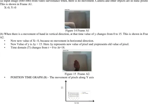
(a) Input image (640×480) from video surveillance when, there is no movement. Camera and other objects are in static position. This is shown in Frame A1.
X=0, Y=0
Figure 14 Frame A1
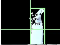
(b) When there is a movement of hand in vertical direction, at that time value of y changes from 0 to 15. This is shown in Frame A2.
• Now new value of X= 0, because no movement in horizontal direction.
• New Value of y is ∆y = 15. Here ∆y represents new value of pixel and yrepresents old value of pixel. • Time domain (T) changes from t = 0 to ∆t=18.
Figure 15 Frame A2. • POSITION TIME GRAPH (B) - The movement of pixels along Y axis
Figure 16 position time graph shows movement of pixels according to y axis
In this Position-Time Graph, Value of pixel in vertical plane in shown. As soon as pixel moves from lower position to higher position there is a change in time domain.
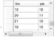
Table 3 Comparison of Angle change method with colour method
Value of x Value of y Position of pixel Time taken by colour method T(ns)
Time taken by Angle change method T(ns)
X=0 Y=0 0 44 0
X=5 Y=0 15 48 18
X=7 Y=0 11 55 20
X=12 Y=7 16 50 21
Angle change method is compared with colour based method [8] on the basis of time that a pixel taken to change its position. Zhen Qian [8] gave a method called space vector difference method for detection of moving objects. He gave good results but our environment is totally different for implementing the colour method. Colour method depends upon intensity of light. Light effect plays an important role. We implemented this method in a room having light effect. We can see from this table Angle change method takes less time than colour method and Time is zero when there is no movement of pixels (x=0, y=0). On the other hand colour method takes 44 ns when there is no movement because there is so much fluctuations in colour method due to intensity of light. Angle change method removes the disadvantages of other method like background model and intensity of light because this method does not depend on background model and intensity of light. Application of Angle change method is in security area like Banking.
5. CONCLUSION AND FUTURE SCOPE
From this paper we can conclude that proposed algorithm 2 is better than algorithm 1 that are analysed in this paper work. Second algorithm (Angle change method) takes less time in capturing and saving the picture than algorithm 1. Angle change method removes the disadvantages of previous methods like background model and used less hard disk than others for saving the pictures.
The field of Image Processing has been growing at a very fast pace. The work proposed in this paper portrays a small contribution in image processing field. The proposed moving object detection technique can provides a good platform for further research work in this respect. This work further can be enhanced to creating calls using SIM card programming with mobiles. It will provide more security to restricted areas like banking. Other motive of our research is on improving the quality of cameras.
6.REFERENCE
[1] Bugeau, Aurelie. and Perez, Patrick. “Detection and Segmentation of moving objects in highly dynamic scenes”, France conference of computer and
science, (2007).
[2] Hou .Zhiqiang and Han .Chongzhao, “A background reconstruction algorithm based on pixel intensity classification in remote video surveillance
system”, National key fundamental research program in china, (2001).
[3] Yokoyama, Masayuki. andPoggio, Tomaso. “A contour based moving object detection and tracking”,(2005).
[4] Bugeau, Aurelie. and Perez, Patrick. “Detection and Segmentation of moving objects in highly dynamic scenes”, France conference of computer and
science, (2007).
[5] Y. Shireen. Elhabian and H .Ahmed, “Moving object detection in spatial domain using background removal techniques”, Recent patents on computer
science, (2009), vol. 1.
[6] Zheng, Xiaoshi. and Zhao, Yanling. “An automatic moving object detection algorithm for video surveillance applications”,IEEE, International
conference on Embedded software and systems, vol. 541-543 (2009).
[7] Shafie, A. A. and Hafiz, Fadhlan. “Moving object detection using optical flow”, World Academy of science and technology, vol. 559-561 (2009).
[8] Quian, Zhen. and Huang, Debao. “Moving objects detection based on Space Vector Difference”, IEEE, International conference of Mechanics and