Heat Transfer Enhancement in a Tube Fitted with
Modified Nozzle-Turbulators and Wire-Coil
Akeel Abdullah Mohammed
Al-Nahrain University/College of Engineering/Mechanical Department akeelabdullah@yahoo.com
Abstract--Experimental investigation has been conducted to study the enhancement of forced convection heat transfer by means of passive techniques for a turbulent air flow through an Aluminum test tube. The length to diameter ratio is 40. Reynolds number ranged from 6000 to 13500 with boundary conditions of constant heat flux of 357 W/m2. The augmentation process is done by using six different arrangements which are; convergent nozzle CN, divergent nozzle DN, convergent-divergent nozzle CDN, divergent-convergent nozzle DCN, combined convergent-divergent nozzle CCDN and combined convergent-divergent-convergent nozzle CDCN. Then, the DN was modified by using three different modifications; perforation (triangle holes, square holes and circle holes), combining the Nozzle-Turbulator with Wire-Coil, and combining the Nozzle-Turbulator with drilled plate CNDP. The results at the same Reynolds number show that the CNDP provides higher heat transfer rates by 408% than that in a plain tube and friction factor 35 times that provided by the plain tube. On the other hand the perforated Nozzle-Turbulators with triangle holes give a thermal performance factor of 1.7 which is the highest thermal performance factor among all other augmentation devices used in the present study.
Index Term-- heat transfer; tube; conical ring; nozzle turbulator.
I. INTRODUCTION
Heat transfer techniques with a passive method have been developed and applied in many engineering applications such as heat exchangers, combustion chambers, gas turbine blades and electronic devises. Development of high-performance thermal systems stimulated the interest in methods to improve the heat transfer. In general the study of the improvement of the heat transfer performance is referred to as the heat transfer augmentation, enhancement, or intensification. The main thermo-hydraulic goals of the heat transfer enhancement include: - reducing the size of a heat exchanger required for a specific heat duty, increasing the heat duty of an existing heat exchanger, reducing the approach temperature difference for the process stream, or reducing the pumping power [1].
Many researchers studied the heat transfer augmentation techniques using modified twisted tape, modified conical ring, coil wire, etc. Promvonge and Eiamsa (2006) [2], showed that the using of the conical nozzle and the snail can help to increase considerably the heat transfer rate over that of plain tube by 278% and 206% respectively, and the use of conical nozzle in common with snail leads to maximum heat transfer rate that is up by 316% for range of Reynolds number was (8000-18000) at pitch ratios (2, 4 &7). They proved (2006) [3] for the same range of Reynolds number that the use of the V-nozzle can help to increase considerably the heat transfer rate at pitch ratio of (2, 4 and 7)
number of air ranged from 4000 to 20000. They concluded that the tube fitted with circular-ring turbulator enhances the heat transfer rate in around (57% to 195%) compared with that in the plain tube. Bankar and Pathare (2010) [12], examined V-nozzle inserts with pitch ratio 5.0 in a circular tube with L/D of 28 and Reynolds number ranged from 21500 to 48500. It was found that the use of the V-nozzle could help to increase considerably the heat transfer rate at about 140% over the plain tube with a maximum gain of enhancement efficiency of 1.19. Eiamsa and Promvonge (2010) [13], experimented the diamond-shaped turbulators in tandem arrangements inside tube with included cone angle of 15°, 30° and 45° and tail length ratios 1.0, 1.5 and 2.0 under Reynolds number ranged from 3500 to 16500. The results showed that the included cone angle decreases with the rise of the tail length ratio. For turbulator with 45° cone angle, the heat transfer was increased by 67%, 57% and 46% for tail length ratio 1.0, 1.5 and 2.0, respectively.Ibrahim and Kashif (2012) [14],used as trapezium-nozzle a passive technique to enhance heat transfer process inside tube with three different pitch ratios 2, 4 and 7, under Reynolds number ranged from 8000 to 16000. The authors concluded that the maximum gain of the Nusselt number was obtained for the smallest pitch ratio used (2) in the range of 202% to 257% compared with the plain tube. Karakaya and Durmus (2013) [15],devised the conical spring turbulators for three different conical arrangements (CN, DN and CDN) and three different cone angles 30°, 45° and 60° in Reynolds number range of 10000 to 34000. It was found that the best results in terms of heat transfer, are respectively DN, CDN and CN arrangements, while the turbulator best results were obtained, for cone angles 30°, 45° and 60°; respectively. Nishidha and. Basavaraj (2013) [16] found the heat transfer in tube with conical spring inserts is higher by 77.88% than that in smooth tube (i.e, without using any inserts). Durgesh et al [17] (2017) used copper and aluminum conical rings with two pitches of 3 cm and 5 cm respectively to enhancement heat transfer process in circular tube. The results show that the copper conical insert of 3mm thick and 30 mm pitch has greater Nusselt number than aluminum conical ring insert in the range of 88% to 141%. In order to achieve the goal of the present study; an appropriate testing unit was designed and constructed to investigate the turbulent forced convection heat transfer augmentation in a in a uniformly heated horizontal circular test tube for a specific range of Reynolds number from (6000 to 13500). The heat transfer augmentation has been investigated by using the passive techniques of turbulators, perforated turbulator, combined nozzle-turbulators with wire coil and combined nozzle-nozzle-turbulators with drilled plate. For all the previous augmentation procedures a performance evaluation has been made with comparison between the augmented arrangements and the plain tube to find the effect of the inserts on heat transfer and pressure drop, and to develop an empirical equation for the best tested augmentation procedures.
II. EXPERIMENTAL SETUP
The experimental rig is shown schematically in Fig.(1). The experimental setup (the open air flow loop) can be divided into two main sections, the air supply section and
the heating section. The open air flow loop used in the system consists of an electrical centrifugal air blower with 2800 rpm and 764 W AC power motor. This blower is the source that provides air flow for the system. A flow control valve (ball valve) was installed on the pipe line located on the blower outlet to control the air flow. A scaled panel was fixed to the valve and used with the flow control valve handle to indicate the amount of air flow through the system.
The outlet of the control valve is connected with a cast iron pipe that supplies the orifice plate with the air flow. The dimensions of the cast iron pipe are 1510 mm length and 75 mm outer diameter and 71 mm inner diameter. The orifice plate has been installed on the pipeline to measure the flow rate of the air that enters the heat transfer testing unit. The orifice plate is then connected to a cast iron pipe with a length of 480 mm and outer diameter of 75 mm and inner diameter of 71 mm. The cast iron pipe is connected directly to a flexible hose which is attached firmly to the settling chamber to avoid any leakage. The settling chamber is constructed from a cubic iron frame with six Perspex walls (300 mm×300 mm). It is used to reduce the fluctuations in the air flow before entering the test tube by using the straightener that is located inside the settling chamber.
The heating section was designed and constructed carefully to study the forced convection heat transfer process and the friction factor with recording the data of (temperature, volumetric flow rate and the pressure drop) of the bulk air flow at the steady state condition. It is composed of a 1350 mm length of aluminum pipe with 45 mm inner diameter and 2.5 mm of its wall thickness. To achieve the uniform heat flux boundary condition, the aluminum pipe was heated electrically by using a continuous and uniform winding of a flexible electric heater wire type KANTHAL made from (FeCrAl) with a pitch of 10 mm. The heating wire has an 0.6 mm diameter and a 26 m length. It was carefully placed in ceramic beads to insulate it electrically from the aluminum pipe. To reduce the heat loss from the test unit a multilayer thermal insulation was added. The first layer is the asbestos rope with a thickness of 20 mm. The second insulation layer is the plaster with a thickness of 5 mm followed by a layer of glass wool with a thickness of 7 mm.
permanently on the inlet and outlet tube to find the pressure drop through the heating section by a water manometer connected to the tapping. A single thermocouple was attached inside the settling chamber to record the inlet air temperature
to the heating section while there are two thermocouples located on the exit teflon disk to record the average outlet air temperature.
III. AUGMENTATION TECHNIQUES
The turbulaters are made from Aluminum with a truncated hollow cone shape. The nozzle-turbulators are constricted with the length of a=45 mm and with ends diameters of D=45 mm and d=22.5 mm. The insertion of the nozzle-turbulators were made thoroughly inside the heating section by press with pitch ratio of (PR = l/D = 5). The nozzle-turbulator was employed to generate the reverse flow from the separation and reattachment of the boundary layer occurring between the nozzle-turbulators.
A. Nozzle-turbulators
They were mounted over the testing unite with six different arrangement , as illustrated in Fig.(2), as follows: Converging turbulators array (CN), Diverging nozzle-turbulators array (DN), Converging-diverging turbulators array (CDN), Diverging-converging nozzle-turbulators array (DCN), Combined converging-diverging nozzle-turbulators array (CCDN), and Combined diverging-converging nozzle-turbulators array (CDCN).
Fig. 2. Sketchs of the Nozzle- Turbulators arrangements.
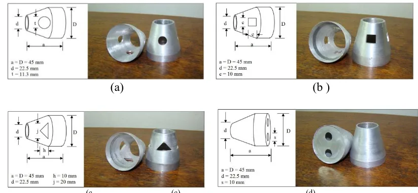
B. Perforated Nozzle-turbulators
Nozzle-turbulator was perforated with four holes which had three geometric shapes; circle, square, and triangle; as shown in Fig.(3-a, b, &c). All the holes (regardless of its shape) were fabricated to have the same area of 100 mm2.
C. Nozzle- Turbulators Combined with Drilled Plate in
The aluminum circular plate was designed to be fitted in the bigger end of nozzle-turbulators that arranged inside the heating section with two holes at diameter of 10 mm. These combined Nozzle-turbulator were arranged in the test tube with an array such that the holes in the plates to be crossed as shown in Fig.(3-d).
D. Nozzle-Turbulators Combined with Wire Coil.
The wire coil was designed to be fitted in the core of the nozzle-turbulators arranged inside the heating section. Two wire coils with different coil pitch were used in the present work. The wire coils are made of steel with wire diameter of b=2 mm and coil outer diameter of B=21 mm which is a little less than the small end diameter of the nozzle-turbulators to facilitate the insertion of the wire coil inside it. The length of wire-coil used is L=1.35 m and the coil pitches used are e=8 mm and 14 mm, as shown in Fig. (4).
IV. Data Analysis
To analyze the process of heat transfer from the test tube to the air, a software program was applied using the (MATLAB-2009) to perform all calculations of the data analysis. By taking all the thermophysical properties of air as follows:
The overall bulk air temperature (Tb) is calculated as follows [18]:
(1)
The heat transferred to the air by convection can be calculated as follows:
(2) (3)
The heat transferred from the test tube to the working fluid by convection (Qconv) can be calculated in another manner as follows:
(4)
Where (Qe) is the heat supplied by the electrical winding heater on the test tube that is taken as the total input power which is calculated from:
(5) Fig. 4. Sketch of the wire coil insert combined with the Nozzle-turbulator.
(a) (a) (b )
(c. (c) (d)
Qcond represents the heat loss by conduction that is found by Fourier's law as follows:
(6)
where (Tins) is the average insulation outer surface temperature and ( w) is the average test tube surface temperature that is recorded from eighteen points as follows:
(7) where (Tw) is the local test tube surface temperature.
while ( T) is the total thermal resistance of the multilayer insulation which is found by:
Each one of the thermal resistances ( ) could be found by: (8)
the heat transfer by radiation is calculated by Stefan-Boltzmann law:
(9)
the heat lost axially from the test tube is calculated to give an average value of 3% from the total heat supplied by the electrical heater:
(10)
Finally, the heat gained by air with convection (Qg) can be calculated as follows:
(11)
To find the average heat transfer coefficient (h), Newton's second law of cooling is used as follows:
(12) The friction factor (f) is found from:
(14) where:
∆Pt = pressure drop through the test tube (Pa).
V. Results and Discussion A. Nozzle-Turbulators
Generally all the nozzle-turbulator arrangements leads to a considerably higher heat transfer rates than that of the plain tube. Fig.(5) reveals that the DN arrangement gives higher values of heat transfer rate (average Nusselt number) than that of other nozzle-turbulator arrangements due to its geometry that provided the greatest interruption to the flow with the greatest contact surface area between the heated test tube wall and the tested fluid, and these values increase with increasing of Reynolds number. The enhancement of the heat transfer rate by using the nozzle-turbulators is attributed to its influence in disrupting the boundary layer and the reverse flow that enhance the convection heat transfer process. In fact the best mixing between the wall region and the core region results in the highest disruption in the boundary layer that enhances the process of convection heat transfer. Also the reverse flow resulted from the nozzle-turbulator enhances the convection by augmenting the effective axial Reynolds number with reducing the flow cross sectional area, which affect directly and severely the mean velocity and temperature gradient that produce greater heat fluxes and momentum
because of the larger effective potential force. The DN, CN, CDN, DCN, CCDN and CDCN presented a heat transfer rate higher than that of the plain tube by 317%, 231%, 268%, 295%, 111% and 187% ; respectively.
Fig. 5. Variation of average Nusselt number with the Reynolds number for different Nozzle-Turbulator arrangements
Fig.(6) illustrates the variation of the friction factor with the Reynolds number for the plain tube and all the turbulator arrangements. It can be seen that using any nozzle-turbulator arrangement creates a greater friction factor than that of the plain tube because the interaction of the pressure forces with the internal forces of the boundary layer blocking the flow causes dissipation of the dynamic pressure of the tested fluid, in addition to the high viscous losses near the pipe wall. It can be noticed from Fig.(6) that the friction factor for all the nozzle-turbulator arrangements decrease with the increase of Reynolds number. The DN arrangement gives the highest pressure loss among other nozzle-turbulator arrangements. The friction factor of tube with DN is 19 times that of the plain tube.
Fig. 6. Variation of friction factor with the Reynolds number for different Nozzle-Turbulator arrangements.
B. Perforated Nozzle-Turbulators
fitted with the perforated nozzle-turbulator (regardless of the holes shape) are higher than that of the plain tube at the same Reynolds number. This can be attributed to the perforated nozzle-turbulator effect on the destruction of the thermal boundary layer near the surface of the test tube which is caused by the interruption of the air flow through the perforated nozzle-turbulator. Although all these perforated nozzle-turbulators have the same number of holes with the same area (in spite of its different hole shapes), but the results show that they do not provide the same heat transfer rate. Actually the heat transfer rate for triangle holes, circle holes and square holes were 253%, 245% and 231% higher than those of the plain tube, respectively; on the corresponding Reynolds number. This is mainly because of the geometry of the hole that has a specific effect on the air flow inside the hole. The vortices formed and the reverse flow that takes place in the area between the wall of the test tube and the nozzle-turbulator have a direct impact on the rate of heat transfer. The triangle hole creates a higher disruption to the flow than that created by the circular hole and the squire hole. On the other hand the results reveal that using the traditional nozzle-turbulator gives a higher heat transfer rates than the heat transfer rates given by the perforated nozzle-turbulator at the same Reynolds number in about (64%-86%) due to the lower turbulence intensity in the tube provided by the perforated Nozzle-turbulator.
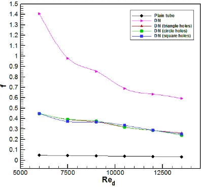
The effect of the perforated nozzle-turbulator on the pressure drop across the plain tube is shown in Fig.(8). This figure reveals that there is a significant increase in the pressure drop by using the perforated nozzle-turbulator compared with that of the plain tube at the same Reynolds numbers. The experimental data shows that the friction factor for the perforated Nozzle-turbulator with triangle holes, circle holes and square holes were about 747%, 740% and 738%, respectively; higher than those of the plain tube. As it could be noticed that the difference between these friction factors percentage ratios do not cross 9% but in fact they lead to a much bigger difference between there corresponding average Nusselt numbers that reaches up to 22%. It can be observed that the friction factors in the tube fitted with perforated nozzle-turbulator are smaller than those provided by the traditional nozzle-turbulator at the corresponding Reynolds number. This can be attributed to the fact that the perforation with any shape reduce the obstructing of the nozzle-turbulator to the air flow which lead certainly to reduce the pressure drop across the plain tube.
Fig. 7. Variation of average Nusselt number with the Reynolds number for different perforated Nozzle-Turbulator.
Fig. 8. Variation of friction factor with the Reynolds number for different perforated Nozzle-Turbulator.
C. Nozzle-Turbulators Combined with Wire Coil
demonstrate that the increasing of coil pitch increases the heat transfer rate because of a better mixing between the flow regions witch obviously increase the convection. It is noticed also that the tube fitted with combined nozzle-turbulator and wire-coil with 14 mm coil pitch gives a higher heat transfer rates than those provided by the combination with 8mm pitch ratio.
Fig. 9. Variation of average Nusselt number with the Reynolds number for combined Nozzle-Turbulator with Wire-Coil.
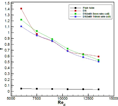
The effect of fitting the test tube with combined nozzle-turbulator and wire-coil on the pressure drop through the test tube is illustrated in Fig.(10) which shows that the pressure drop provided by the combined nozzle-turbulator and the wire-coil was significantly higher than that of the plain tube at the same Reynolds numbers. Also the results show that using 8 mm coil pitch gives a higher pressure drop than that with 14 mm coil pitch and that of the divergent nozzle-turbulator alone in the Reynolds number range (7000 to 11500). This is a reasonable result because the wire-coil insert provides an extra friction between the air flow core region and the wall region.
Fig. 10. Variation of friction factor with the Reynolds number for combined Nozzle-Turbulator with Wire-Coil.
D. Nozzle-Turbulators Combined with Drilled Plate in the Outlet of
the Nozzle
The influence of using a nozzle-turbulator combined with drilled plate on the heat transfer rate is plotted in Fig.(11).
Fig. 11. Variation of average Nusselt number with the Reynolds number for combined Nozzle-Turbulator with drilled plate.
This figure demonstrates that at a given Reynolds number and for the whole range investigated, the heat transfer rates in the tube fitted with this combination of turbulators are higher than those of the plain tube and those of the traditional divergent nozzle-turbulator. In other word this combination of turbulators provides an enhancement to the heat transfer rate in the tube with 408% and 91% over that provided by the plain tube and divergent nozzle-turbulator; respectively. This enhancement could be attributed to the high destruction of the thermal boundary layer and the great turbulence generation. Also the augmentation of heat transfer rate is greatly amplified at high Reynolds numbers and leads to higher turbulence level which considerably increase the convection heat transfer rates. In addition these combined nozzle-turbulators are arranged in the test tube with array that the holes in the plates to be crossed that provide a high circulation of the air flow to give a superior heat transfer rate than any other augmentation devise or combination of devices tested in the present study.
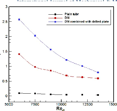
Fig. 12. Variation of friction factor with the Reynolds number for combined Nozzle-Turbulator with drilled plate.
This high friction factor can be attributed to the increase in the generated turbulence provided by the effect of the drilled plate in presenting a high blockage to the flow that is offered even a stronger turbulence intensity.
VI. PERFORMANCE EVALUATION
It is important to evaluate the performance of each enhancement technique that has been used in the present study to find the most practical technique, This evaluation is done by calculating both effects of the enhancement device; on the heat transfer rate and on the pressure drop together by presenting them in to the form of the thermal performance factor (η) at constant pumping power witch is:
(15) where:
Nud E = average Nusselt number with the enhancement device.
Nud t = average Nusselt number for the plain test tube.
fE = friction factor with the enhancement device. ft = friction factor for the plain test tube.
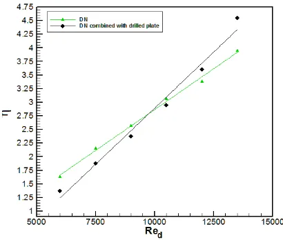
As shown in Figs.(13 to 16), the variation of the thermal performance factor increases with the increasing of Reynolds number for all the cases of the augmentation devices. This is attributed to that increasing the Reynolds number leads to increasing the Nusselt number and decreasing the friction factor.
Fig. 13. The effect of Nozzle-Turbulator arrangement on the thermal performance factor.
Fig.(13) reveals that for most of the tested range the divergent nozzle-turbulator arrangement provide the highest thermal performance factor except for that at Reynolds number less than 9000, at which the divergent-convergent arrangement provide a greatest thermal performance factor. Therefore, the divergent nozzle-turbulator arrangement will be taken as a comparison reference with other augmentation cases. Fig.(14) illustrates that for the perforated nozzle-turbulator, the triangle holes provide the highest thermal performance factor. Also, they provide thermal performance factor higher than that of the divergent nozzle-turbulator.
Fig. 14. The effect of Nozzle-Turbulator perforation on the thermal performance factor.
without drilled plate for the Reynolds number higher than 10500.
Fig. 15. The effect of combining the Nozzle-Turbulator with the Wire-Coil on the thermal performance factor.
Fig. 16. The effect of combining the Nozzle-Turbulator with the drilled plate on the thermal performance factor.
VII. EXPERIMENTAL CORRELATIONS
By analyzing the data obtained from using all the augmentation devices in the present study to develop the experimental correlations in terms of average Nusselt number and friction factor for the range of Reynolds number from 6000 to 13500, with using the least square method in the (STATISTICA 6.0) program to evaluate the constant values (a, b, n and m) for the following general empirical equations of average Nusselt number and friction factor:
(16) (17) The values of a, b, n, and m are given in Table I.
Table I
Constants values of empirical equations of average Nusselt number and friction factor.
Case Constants values
a b n m
PT 0.00154 1.066 2.0416 0.427
CN 0.17424 0.682 1900.5
DN 0.1396 0.731 6810
CDN 0.17898 0.69 4159.4
DCN 0.47248 0.592 1035.6
CCDN 0.08008 0.718 87.449
CDCN 0.06249 0.778 408.04
CNDP 0.01767 0.977 39472
For perforated divergent turbulator and Nozzle-turbulator fitted with Wire-Coil; the average Nusselt number and friction factor empirical equations at the same range of Reynolds number given above are respectively given as follows:
(18) (Z = 0.78889 - 1.06667)
(19)
(20) (Y = 0.38095 - 0.66667)
(21) where:
Z = the ratio of hole perimeter to the nozzle-turbulator length. Y = e/B = the Wire-Coil pitch ratio.
It was found that the maximum deviation for the Nusselt number were (±3%) while the maximum deviation for the friction factor was (±9%) for all cases.
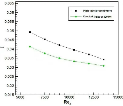
VIII. VALIDITY
The present experimental results with the heat transfer in a uniformly heated circular tube without turbulators (plain tube) have been compared for validity with the previous works in the form of average Nusselt number and friction factor. The correlations of Kongkait Paiboon are given as follows:
4 . 0 709 . 0
Pr
Re
057
.
0
Nu
(22) For 4000≤ Re ≤ 2 × 10⁴ 284 . 0
Re
458
.
0
f
(23) For 4000 ≤ Re ≤ 2 × 10⁴Fig. 17. Nusselt number verification for the plain tube.
Fig. 18. Friction factor verification for the plain tube.
IX.CONCLUSIONS
Experimental investigation to study the enhancement of forced convection heat transfer by means of passive techniques for a turbulent air flow through an Aluminum test tube has been carried out. Several conclusions can be drawn as follows:
1. All the turbulators used in the present study give an increasing heat transfer rate and the pressure drop through the test tube compared with the case of plain tube for the tested range of Reynolds number.
2. The divergent arrangement of the Nozzle-Turbulator provides the highest heat transfer rate and the highest pressure drop among all other nozzle-turbulator arrangements.
3. For the perforated divergent nozzle-turbulator:
a) The triangle hole shape perforation provided a higher heat transfer rates than those of the circular and square hole shapes perforation.
b) The shape of the perforation hole does not affect on the pressure drop through the test tube in all the tested shapes.
c) The perforated divergent nozzle-turbulator (for all the tested hole shapes) reduces the heat transfer rate and the
pressure drop compared with the case of non perforated divergent nozzle-turbulator.
4. For combined divergent nozzle-turbulator with the wire-coil, the heat transfer process improves as coil pitch increases with decreasing of pressure drop, and gives a lower heat transfer rate than that of the divergent nozzle-turbulator alone 5. The combined divergent nozzle-turbulator with the drilled plate offers the highest heat transfer rate and the highest pressure drop over all other cases taken in the present study. 6. The perforated nozzle-turbulator with the triangle holes provides the highest thermal performance factor except for Reynolds number higher than (11500) after which the combined nozzle-turbulator with the drilled plate gives the greatest thermal performance factor.
NOMENCLATURE A area (m2)
B coil outer diameter (m) Co orifice discharge coefficient Cp specific heat of air (kJ/kg.K) D tube diameter (m)
d nozzle-turbulator small end diameter (m) e coil pitch (m)
f friction factor FƐ emissivity=0.04 FG view factor=1
h average heat transfer coefficient (W/m2.K) I current (Ampere)
j base length of the triangle perforation in the nozzle-turbulator(m)
L test tube length (m)
l pitch length between nozzle-turbulator (m) mass flow rate of air (kg/s)
Nud average Nusselt number= Pr Prandtl number=
Q" volumetric flow rate (m3/s) h i 2
.K /W)
Red Reynolds number based on diameter ri inner radius of lagging (m)
ro outer radius of lagging (m)
s diameter of the hole in the drilled plate (m) t diameter of the circular perforation in the
nozzle-turbulator (m) T temperature (K)
To outlet air temperature (K) Ti inlet air temperature(K) w average wall temperature (K) U mean axial velocity of air (m/s) V voltage (volt)
Z hole perimeter to nozzle-turbulator length ratio ∆P pressure drop (Pa)
Greek Symbols
µ viscosity of air (kg/s.m) β di io
σ S f -Boltzmann constant=5.669 × 10⁻⁸ (W/m2.K4)
Subscripts a air b bulk air c cross section E enhancement device s surface
t total w wall Abbreviations
CDN Convergent Divergent Nozzle-Turbulator CHF Constant Heat Flux
CN Convergent Nozzle-Turbulator CWT Constant Wall Temperature
DCN Divergent Convergent Nozzle-Turbulator DN Divergent Nozzle-Turbulator
OTEC Ocean Thermal Energy Conversion
REFERENCES
[1] A. E. Bergles, "Techniques to augment heat transfer", handbook of heat transfer applications, (Warren M. Rohsenow, James P. Hartnett and Ejup N. Ganic), McGraw-Hill Book Company, New York, Chapter3, pp.3.1-3.6,1985.
[2] P. Promvonge and S. Eiamsa-ard, "Heat transfer enhancement in a tube with combined conical-nozzle inserts and swirl generator", Energy Conversion and Management, Volume 47, pp.2867–2882, 2006.
[3] S. Eiamsa-ard and P. Promvonge, "Experimental investigation of heat transfer and friction characteristics in a circular tube fitted with v-nozzle turbulators", International Communication in Heat and Mass Transfer, Volume 33, pp.591-600, 2006.
[4] K. Yongsiri, S. Eiamsa-ard, C. Thianpong and P. Promvonge,
"Effect of turbulent decaying swirl flow on heat transfer enhancement in a tube", Sustainable Energy and Environment (SEE), the 2nd joint international conference, A-029 (p), 2006. [5] P. Promvonge and S. Eiamsa-ard, "Heat transfer and turbulent flow
friction in a circular tube fitted with conical-nozzle turbulators", International Communications in Heat and Mass Transfer, Volume 34, pp.72–82, 2007.
[6] P. Promvonge and S. Eiamsa-ard, "Heat transfer behaviors in a tube with combined conical-ring and twisted-tape insert", International Communications in Heat and Mass Transfer, Volume 34, pp.849–859, 2007.
[7] P. Promvonge and S. Eiamsa-ard, "Heat transfer in a circular tube fitted with free-spacing snail entry and conical-nozzle turbulators", International Communications in Heat and Mass Transfer, Volume 34, pp. 838-848, 2007.
[8] P. Promvonge and S. Eiamsa-ard, "Heat transfer augmentation in a circular tube using V-nozzle turbulator insert and snail entry", Experimental Thermal and Fluid Science, Volume 32, pp.332-340, 2007.
[9] P. Promvonge, "Heat transfer behavior in round tube with conical ring inserts", Energy Conversion and Management, Volume 49, pp.8-15, 2008.
[10] V. Kongkaitpaiboon, K. Nanan and S. Eiamsa-ard, "Experimental investigation of heat transfer and turbulent flow friction in a tube fitted with perforated conical-rings", International Communications in Heat and Mass Transfer, Volume 37, pp.560-567, 2010.
[11] V. Kongkaitpaiboon, K. Nanan and S. Eiamsa-ard, "Experimental investigation of convection heat transfer and pressure loss in a round tube fitted with circular ring turbulators", International
Communication in Heat and Mass Transfer, Volume 37, pp.568-574, 2010
[12] D. Bankar and N. R. Pathare, "Analysis of heat transfer and friction factor characteristic in circular tube fitted with v-nozzle turbulators", Emerging Trends in Engineering and Technology (ICETET), 3rd International Conference on, pp. 675-679, 2010. [13] S. Eiamsa-ard and P. Promvonge, "Thermal characterization of
turbulent tube flows over diamond-shaped elements in tandem", International Journal of Thermal Sciences, Volume 49, pp.1051-1062, 2010.
[14] E. Ibrahim and E. El-Kashif, "An experimental study on heat transfer and entropy generation in circular tube fitted with trapezium-nozzles", Canadian Research & Development of Sciences and Cultures, Volume 3, pp.74-83, 2012.
[15] H. Karakaya and A. Durmus, "Heat transfer and exergy loss in conical spring turbulators", International Journal of Heat and Mass transfer, Volume 60, pp.756-762, 2013.
[16] A. Nishidha Lokhande1, M. Basavaraj, " An Approach for Enhancement of Heat Transfer Using Conical Convergent Ring Inserts In Tube ",International Journal for Research in Applied Science & Engineering Technology (IJRASET), Volume 3 Issue XII, December 2013.
[17] V. D. Ahire, Yogesh J. Bhalerao, M. S. Dholkawala, “Experimental investigation of heat transfer enhancement in circular pipe using conical ring inserts”, International Journal of Mechanical And Production Engineering, ISSN: 2320-2092, Volume- 5, Issue-3, March 2017.