Abstract—The aim of this work is to evaluate the capacity of earth-air heat exchanger (EAHX) systems to contribute to energy and pollution savings for heating and cooling of buildings. This is fulfilled by means of numerical simulations (dynamic regime) based on coupled model: “weather file/soil model/EAHX/ventilation system/building. Detailed results concerning EAHX efficiency, energy conservation and pollution reduction (in comparison with classical solutions for winter heating and summer cooling), are shown for three different Romanian regions for a single-family separate house.
Index Terms—Earth-air heat exchanger, energy saving, greenhouse gas emission reduction, modeling, simulation, ventilation.
I. INTRODUCTION
The energetic sector, including private households and tertiary field, generates 80% of European Union (EU) total greenhouse gas emissions (GES), being practically the main cause of climatic changes and atmospheric pollution. Consequently, EU has made efforts to find out solutions for decreasing the amount of GES (within EU and worldwide) associated to energy use in order to slow down climatic changes and therefore to limit the global warming [1]. In fact, the major European Union (EU) objective is to increase the energy efficiency by 20% and to reduce the GES by 20 % until the year 2020 [2]. In line with this, according to The Energy End-Use Efficiency and Energy Services Directive (ESD 2006/32/EC), Member States (MS) must achieve a minimum annual energy savings target of 9% by the ninth year in the period from 2008 to 2016. On the other hand, it is well known that buildings are responsible for more than 40% of total final energy consumption and 36% of EU CO2 emissions [3]. Furthermore, EU documents estimate even more energy consumption due to ventilation and cooling of houses in South Europe. Therefore measures to improve energy efficiency in this sector have a strong leverage effect. As a result, for achieving the EU energy saving targets, the very low energy houses and passive houses technology will be an essential tool on this road [4], [5]. This field of action can significantly help to challenge recent pessimistic reports suggesting that current EU measures could achieve energy savings of only about 13% by 2020. In fact, following the
Manuscript received May 26, 2014; revised July 28, 2014. This work was supported by the Romanian National Authority for Scientific Research, CNDI– UEFISCDI under Grant PN-II-ID-JRP-RO-FR-2012-0071.
The authors are with the Thermo-Hydraulic and Protection of the Atmosphere Systems Department, Faculty of Building Services and Equipment, Technical University of Civil Engineering, Bucharest 020396, Romania (e-mail: cteodosiu@yahoo.com, niculita@gmail.com, ralucahohota@yahoo.com).
European Commission‟s proposal in November 2008 for an update of the 2002 Energy Performance of Buildings Directive (EPBD), the Recast was adopted by the European Parliament and the Council of the EU on 19 May 2010 (European Directive 2010/31/EU). One of the highlights of the recast is a strengthening of the energy performance requirements of new as well as existing buildings across the EU. The timescales are mentioned in Article 9 of the Directive, which states that MS shall ensure that “by 31 December 2020, all new buildings are nearly zero-energy buildings and after 31 December 2018, new buildings occupied and owned by public authorities are nearly zero-energy buildings.” The EPBD Recast definition of very low energy building was agreed to: “nearly zero energy building means a building that has a very high energy performance” and “the nearly zero or very low amount of energy required should to a very significant level be covered by energy from renewable source, including renewable energy produced on-site or nearby”. In addition, it is worthwhile to mention that the ventilation system is indispensable in this case as these buildings are extremely well thermal insulated and air tightened.
In this perspective, the use of geothermal heat exchangers for heating and/or cooling of buildings has experienced lately a growing interest. Among these equipments, the earth-air heat exchangers (EAHXs) represent the simplest technical solution. Despite its simplicity (in fact, this is an advantage from all points of view: execution, maintenance, payback, etc.), earth-air heat exchangers lead to important energy savings concerning fresh air supply within ventilation systems of buildings during all the year [6]. Consequently, the objective of this study is to fulfill methodical numerical investigation in order to quantify energy and GES emissions savings, achieved by using earth-air heat exchangers added to ventilation systems for Romanian conditions (climate and typical dwelling built up according to national standards).
II. GROUND TO AIR HEAT EXCHANGER SYSTEM
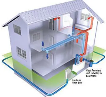
The system functioning is based on outside air circulated through pipes buried in the ground (Fig. 1). The heat exchange takes place between the ground and the air inside the pipes: earth‟s temperature varies from 2-3 meters depth within 5…15ºC all year round, while outside air temperature can range from -20…40ºC, if we refer to situations encountered in Romania. In consequence, at the end of the buried pipes, heat transfer leads to air heating or cooling, depending on the season. Depending on working conditions (length, diameter, thermal conductivity and depth of the tube, air flow, soil characteristics, etc.), the air temperature
Solutions for Energy Conservation and Pollution
Reduction: Earth-Air Heat Exchangers
difference in/out earth-air heat exchanger can reach 10…15ºC.
Fig. 1. Earth-air heat exchanger system (REHAU).
In fact, the thermal performance of earth-air heat exchangers can be theoretically appreciated by means of achieved heat transfer efficiency (or “temperature ratio” [7]):
η = (Ti-To) / (Ti-TS) (1)
where:
Ti: inlet EAHX air temperature (outside air temperature)
To: outlet EAHX air temperature
TS: soil temperature
It is worthwhile to mention that higher efficiency takes place in the summer. Moreover, the air is also dehumidified in the summer due to condensation that occurs on the inner surface of pipes. This helps also to improve thermal comfort and energy savings for air treatment in summer.
III. NUMERICAL MODELING
In order to thorough investigate the behavior of the ground to air heat exchanger, numerical modeling is the most relevant research tool. Therefore, there are numerous studies dealing recently with this subject [8]-[13]. Most of these studies have focused on the heat transfer soil – pipe heat exchanger, taken carefully into account thermal inertia of the ground. In addition, there are also analysis focused on the effect of air velocity and its turbulence on the performance of the ground to air heat exchanger system. These works are mainly based on computational fluid dynamics approach [14]-[16].
On the other hand, there is several simulation tools that can be used for modeling and simulation of the phenomena related to the earth-air heat exchanger thermal conduct: Design Builder + Energy Plus, Pleiades + Comfie, Trnsys, eQuest (DOE-2), Voltra, WTK2, WKM, etc. Among these, by far the best known and used specialized software is TRaNsient SYstem Simulation Software Program - TRNSYS environment [17].
In fact, Trnsys is flexible, modular software designed to simulate the energy performance of dynamical systems. It is commercially available since 1975. Nowadays, Trnsys has become a reference worldwide in the field of simulation of
buildings and systems behavior in dynamic regime. Some 50 families of components ("types"), available in standard library, allow simulating, in transient conditions: buildings (mono or multi zonal), the simplest as the most complex heating and cooling systems, innovative building services and equipment systems, etc. Other components can couple the simulation with the weather, building occupancy (scenario concerning internal loads), use of different forms of energy, and generate the desired outcomes.
As a result, we developed comprehensive Trnsys simulation models in dynamic regime for coupling building-ventilation (with earth-air heat exchanger system). The main components of these models and their inter-connections are shown in Fig. 2.
Fig. 2. Key of the numerical model.
Furthermore, we present below the characteristics of the main model components (weather data, building, soil, buried pipe model), as well as the main assumptions taken into consideration.
- Weather data, based on “weather file” has the following major objective: reading weather data at regular intervals from a data file, conversion to a desired system of units and processing solar radiation data to obtain tilted surface radiation and the angle of incidence for an arbitrary number of surfaces. In our study we used the file with weather data for 3 Romanian cities (these data contain the outdoor temperature, humidity and solar radiation - direct, diffuse and global).
- Building, component for the house thermal behavior modeling contents non-geometrical balance model with one air node per zone, representing the thermal capacity of the zone air volume; the balance equation takes mainly into account convective heat flux to the air node, coupling between zones by means of air mass flow, radioactive heat flux to the walls and windows [17]. The walls are modeled using transfer function technique (response factors).
taken into account: the soil is homogenous and the soil type does not change around and along the tube of the earth-air heat exchanger.
- Buried pipe model for air to soil heat transfer (the buried pipe is surrounded by a 3-dimensional finite difference conduction network). The proposed model is developed particularly for building energy transient simulations, thus the following hypothesis have been made: only conduction heat transfer is taken into account; the influence of moisture transfer or ground water flows are neglected; ground thermal properties are considered homogenous in the vicinity of the pipe. Axial heat transfer in the soil along the pipe is neglected and the conductive heat transfer is also neglected inside the pipe. Furthermore, it is also assumed that the pipe material used is isotropic and homogeneous.
Finally, all thermophysical properties are considered constant and they are evaluated at an average temperature.
IV. CASE STUDY
We introduce in this section the main characteristics of our case study.
A. Building
The house taken into account is characteristic for the new dwellings built up in Romania nowadays (single-family separate house). The building has ground floor and two levels (total floor area and total volume are 120 m2 and 324 m3, respectively). Other geometrical characteristics are shown in Table I.
TABLEI:ENVELOPE ELEMENTS SURFACES (M2) Windows
(N, S, E, W)
Walls (N, S, E, W)
Roof (horizontal)
Floor on ground 35.84 119.04 60.00 60.00
Envelope thermal insulation of the house is according to national technical regulations [20]. Thermal resistance values for each envelope element are given in Table II (including also these values corrected by thermal bridges – specified between parentheses).
TABLEII:ENVELOPE THERMAL RESISTANCES (M2·K/W) Windows Walls Roof Floor on ground
0.787 3.369 (2.527)
5.263 (5.105)
6.622 (5.430)
Internal loads taken into consideration within the simulations are according to common occupation of the dwelling (3 persons, 420 W from equipment and lighting, 5 W/m2).
Temperature set points are as follows: winter 20ºC, summer 26ºC.
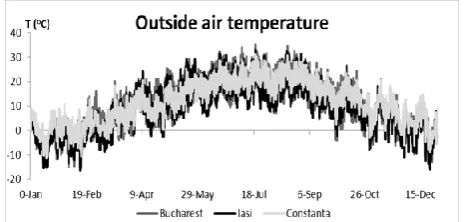
The house described above has been considered located in three Romanian cities, corresponding to different climatic zones of the country (Fig. 3 and Fig. 4): Constanta, on the
Black Sea coast - moderate continental climate with
considerable maritime and some subtropical influences (minimum/maximum outside air temperature: -11,2ºC/31,1ºC according to the Meteonorm weather database); Bucharest, capital – temperate humid continental
climate (minimum/maximum outside air temperature:
-15,4ºC/35,4ºC according to the Meteonorm weather database); Iasi, in the North-East of Romania– pronounced continental climate, influenced by air masses of Eastern origin, with very cold winters and hot summers (minimum/maximum outside air temperature: -16,5ºC/33,0ºC according to the Meteonorm weather database).
Fig. 3. External air temperature (Meteonorm weather database).
Fig. 4. Total solar radiation (Meteonorm weather database).
B. Earth-Air Heat Exchanger System
The fresh air flow rate of the house ventilation system is 162 m3/h (meaning 0.5 h-1).
Table III presents the main thermal properties of the earth-air heat exchanger pipe.
TABLEIII:EAHXPIPE CHARACTERISTICS
Density (kg/m3)
Specific heat (J/kg·K)
Thermal conductivity (W/m·K) 900 2900 0.12
Pipe diameters taken into account during the simulations are: 110, 160, 200 and 400 mm. Tubes mounting depth is 2 m and the total length of the buried part of the system (the “active” heat transfer part) is 40 m (single pipe). These parameters have been chosen based on “rules of thumb” regarding the standard design of earth-air heat exchanger system for single-family houses up to 150 m2 floor area. In fact, previous studies [21] showed that, for shorter circuits (25…40 m) the air temperature at the exit of the earth-air heat exchanger system does not approach the soil temperature, while bigger lengths do not lead to significant improvements of heat transfer.
V. RESULTS
be predicted by using its efficiency as shown above, based on equation (1). The annual mean earth-air heat exchanger efficiency for different situations is shown in Table IV, based on hourly time step simulations values.
It is worthwhile to notice that the outside air temperature annual variation (depending on the zone climate) has not any influence, in this case, on the earth-air heat exchanger annual effectiveness. This happens because the air temperature after passing the earth-air heat exchanger is approaching the ground temperature – basically the same, regardless the climate.
TABLEIV:EAHXEFFICIENCY (%)
Solution / City Constanţa, Bucharest, Iaşi EAHX, D = 110 mm 79.9
EAHX, D = 160 mm 88.9 EAHX, D = 200 mm 92.6 EAHX, D = 400 mm 97.5
Fig. 5. Constanţa (heating/cooling demand without/with EAHX).
Concerning the integration of the earth-air heat exchanger within the ventilation system, we show (Fig. 5- Fig. 7) the diminution of the winter heating power and summer cooling power for the cities taken into account. The comparisons are
given for two diameters, 160 mm and 200 mm, usually recommended for single-family houses with floor area between 100-150 m2.
Based on the previous results, we summarize in Table V the energy consumption values in various situations (without/with EAHX).
Fig. 7. Iaşi (heating/cooling demand without/with EAHX). TABLEV:ENERGY CONSUMPTION (KWH/M2,YEAR) Solution / City Constanţa
heating cooling without EAHX 30.03 143.91 EAHX, D = 110 mm 21.79 130.27 EAHX, D = 160 mm 20.88 128.75 EAHX, D = 200 mm 20.52 128.1 EAHX, D = 400 mm 20.02 127.31
Solution / City Bucharest heating cooling without EAHX 40.98 126.26 EAHX, D = 110 mm 29.57 112.43 EAHX, D = 160 mm 28.32 110.88 EAHX, D = 200 mm 27.81 110.25 EAHX, D = 400 mm 27.13 109.43
Solution / City Iaşi
heating cooling without EAHX 50.31 114.01 EAHX, D = 110 mm 36.73 101.74 EAHX, D = 160 mm 35.55 100.66 EAHX, D = 200 mm 34.93 100.11 EAHX, D = 400 mm 34.13 99.37
Energy savings achieved by introducing the earth-air heat exchanger within the mechanical ventilation system of the dwelling are also highlighted in Table VI.
Based on the values in Table V, it is found that by using the earth-air heat exchanger within the mechanical ventilation system of the house, energy savings for heating are between 8…16 kWh/m2,year. This means overall 960…1920 kWh/year heating savings for the house taken into account, with 120 m2 total floor area. On the other hand, the analysis
of the results clearly reveals the climate influence. For this reason, the cutbacks are most important for the house located in Iasi, while the lowest energy heating reductions occur at Constanta (winter with obvious marine influence).
TABLEVI:ENERGY SAVINGS (KWH/M2,YEAR) Solution / City Constanţa
heating cooling EAHX, D = 110 mm 8.24 13.65 EAHX, D = 160 mm 9.15 15.16 EAHX, D = 200 mm 9.51 15.81 EAHX, D = 400 mm 10.01 16.61
Solution / City Bucharest heating cooling EAHX, D = 110 mm 11.41 13.84 EAHX, D = 160 mm 12.66 15.38 EAHX, D = 200 mm 13.17 16.01 EAHX, D = 400 mm 13.85 16.83
Solution / City Iaşi
heating cooling EAHX, D = 110 mm 13.58 12.27 EAHX, D = 160 mm 14.76 13.35 EAHX, D = 200 mm 15.38 13.90 EAHX, D = 400 mm 16.17 14.64
Concerning summer situation, cooling energy savings are between 12…17 kWh/m2
, year, which means for the house total floor area of 120 m2, total economy for cooling of 1440…2040 kWh/year. This time, as expected due to weather conditions, more substantial savings are attained in Constanta and Bucharest.
TABLEVII:HEATING AND COOLING ENERGY SAVINGS (MWH/YEAR) EAHX
diameter/ solution
City 110 (mm)
160 (mm)
200 (mm)
400 (mm) electric
heating + cooling
Constanţa 1534 1704 1773 1866 Bucharest 1922 2134 2221 2335 Iaşi 2086 2305 2400 2528 gas heating
+ cooling
Constanţa 1586 1762 1833 1929 Bucharest 1994 2214 2305 2423 Iaşi 2170 2398 2497 2630 condensing
gas technique heating + cooling
Constanţa 1445 1604 1669 1757 Bucharest 1798 1996 2078 2184 Iaşi 1941 2144 2232 2351 liquid fuel
heating + cooling
Constanţa 1644 1826 1900 2000 Bucharest 2074 2303 2397 2520 Iaşi 2264 2502 2604 2744 wood
heating + cooling
Constanţa 1958 2174 2263 2381 Bucharest 2509 2785 2899 3048 Iaşi 2770 3064 3190 3360 wood
gasification heating + cooling
Constanţa 1709 1897 1975 2078 Bucharest 2164 2402 2500 2629 Iaşi 2368 2617 2725 2871 pellet
heating + cooling
Constanţa 1644 1826 1900 2000 Bucharest 2074 2303 2397 2520 Iaşi 2264 2502 2604 2744
electric heating 1, gas heating 0.95, condensing gas technique heating 1.1, liquid fuel heating 0.9, wood heating 0.7, wood gasification heating 0.85, pellet heating 0.9 and electrical mechanical compression cooling 3.
The results in Table VIII are presented in terms of resulting CO2 emissions per year, taken into account specific factors to convert “kWh” into “CO2 emissions” and “kg of carbon dioxide equivalent” for different heating energy sources and electrical mechanical compression cooling [22]. Depending on the heating and cooling solution efficiency, and the nature of the energy used (how “clean” is it), we salvage between 89 and 635 kg of CO2 emissions per year.
TABLEVIII:CO2EMISSIONS SAVINGS (KG/YEAR)
EAHX diameter/
solution
City 110 (mm) 160 (mm) 200 (mm) 400 (mm) electric heating + cooling
Constanţa 271 300 313 329 Bucharest 356 396 412 433 Iaşi 402 445 463 488 gas heating
+ cooling
Constanţa 262 291 303 319 Bucharest 345 383 399 419 Iaşi 388 430 448 472 condensing
gas technique heating + cooling
Constanţa 233 259 270 284 Bucharest 305 338 352 370 Iaşi 342 378 394 415 liquid fuel
heating + cooling
Constanţa 346 384 400 420 Bucharest 460 511 532 559 Iaşi 523 579 603 635 wood
heating + cooling
Constanţa 100 111 116 122 Bucharest 120 133 139 146 Iaşi 126 139 145 153 wood
gasification heating + cooling
Constanţa 91 101 105 111 Bucharest 108 120 125 131 Iaşi 112 123 128 135 pellet
heating + cooling
Constanţa 89 98 102 108 Bucharest 105 116 121 127 Iaşi 108 119 124 130
VI. CONCLUSION
The developed model allows describing in unsteady conditions the functioning of earth-air heat exchanger and their coupling with building ventilation systems.
The results make available the contribution and efficiency of this solution to cover the buildings energy consumption for heating and cooling of fresh air. Moreover, case studies taken into consideration for three Romanian climates demonstrate that earth-air heat exchangers can be used as feasible (and inexpensive) complement to conventional heating or air conditioning systems for pretreatment (heating or cooling) of the air within ventilation systems. Energy gains can reach roughly 2000 kWh/year for heating under severe winter conditions and can even overcome 2000 kWh/year for cooling in continental climate (with or without some maritime influences).
In addition, greenhouse gas emissions can be equally reduced. CO2 emissions savings can attain more than half a ton/year in some circumstances (e.g. when liquid fuel fired boilers are employed for heating and direct expansion air conditioning -electrical mechanical compression for cooling).
Further, it is worthwhile to draw the attention to the fact that the use of earth-air heat exchangers implies no chemicals, compressors, burners or other complicated and polluting equipments. The earth-air heat exchanger system needs only fans (already required for the mechanical ventilation system).
Finally, it is worthwhile to mention, as one of the main perspective of this study and its results, the analysis of condensation phenomena inside the buried pipes of the earth-air heat exchanger system. Consequently, the dehumidifying process of humid air that takes naturally place through the earth-air heat exchanger system in the summer can play a significant role in reducing the latent cooling load of buildings. On the other hand, this subject is of particular concern in the case of requirements for acceptable indoor air quality for very high occupant density buildings.
REFERENCES
[1] I. Pop, M. T. Andrei, C. V. Ene, R. Alexe, F. Vartolomei, and P. S. Nedea, “The strategy of European Union regarding climate change,”
International Journal of Energy and Environment, vol. 5, pp. 558-565,
2011.
[2] V. Pozeb, D. Goričanec, and T. Krope, “The future of Europe‟s energy policy: The legislative framework and the soft law instruments,”
International Journal of Energy, vol. 5, pp. 88-95, 2011.
[3] I. Sârbu and C. Sebarchievici, “Thermal rehabilitation of buildings,”
International Journal of Energy, vol. 5, pp. 43-52, 2011.
[4] A. Audenaert and S. H. de Cleyn, “Cost benefit analysis of passive houses and low-energy houses compared to standard houses,”
International Journal of Energy, vol. 4, pp. 46-53, 2010.
[5] H. Voll, E. Seinre, and M. Sööt, “Analysis of heating energy of ventilation and underground heat exchanger in North European passive houses,” International Journal of Energy and Environment, vol. 6, pp. 92-100, 2012.
[6] F. Ascione, L. Bellia, and F. Minichiello, “Earth-to-air heat exchangers for Italian climates,” Renewable Energy, vol. 36, pp. 2177-2188, 2011. [7] J. Pfafferott, “Evaluation of earth-to-air heat exchangers with a
standardized method to calculate energy efficiency,” Energy and Buildings, vol. 35, pp. 971-983, 2003.
[8] P. Hollmuller, “Utilisation des échangeurs air-sol pour le chauffage et le rafraîchissement des bâtiments,” Ph. D. dissertation, Université de Genève, Genève, Switzerland, 2002.
[9] M. de Paepe and A. Janssens, “Thermo-hydraulic design of earth-air heat exchangers,” Energy and Buildings, vol. 35, pp. 389-397, 2003. [10] M. K. Ghosal and G. N. Tiwari, “Modeling and parametric studies for
thermal performance of an earth to air heat exchanger integrated with a greenhouse,” Energy Conversion and Management, vol. 47, pp. 1779-1798, 2006.
[11] V. Bădescu, “Simple and accurate model for the ground heat exchanger of a passive house,” Renewable Energy, vol. 32, pp. 845-855, 2007. [12] S. Thiers, “Bilans énergétiques et environnementaux de bâtiments á
énergie positive,” Ph.D. dissertation, Ecole Nationale Supérieure des Mines de Paris, Paris, France, 2008.
[13] M. Maerefat and A. P. Haghighi, “Passive cooling of buildings by using integrated earth to air heat exchanger and solar chimney,”
Renewable Energy, vol. 35, pp. 2316-2324, 2010.
[14] V. Bansal, R. Misra, G. D. Agrawal, and J. Mathur, “Performance analysis of earth-pipe-air heat exchanger for winter heating,” Energy
and Buildings, vol. 41, pp. 1151-1154, 2009.
[15] V. Bansal, R. Misra, G. D. Agrawal, and J. Mathur, “Performance analysis of earth-pipe-air heat exchanger for summer cooling,” Energy
and Buildings, vol. 42, pp. 645-648, 2010.
[16] J. Vaz, M. A. Sattler, E. D. D. Santos, and L. A. Isoldi, “Experimental and numerical analysis of an earth-air heat exchanger,” Energy and
Buildings, vol. 43, pp. 2476-2482, 2011.
[17] S. A. Klein et al., TRNSYS Version 14.2. User Manual, Solar Energy Laboratory, University of Wisconsin, 1996.
[18] R. Wagner, S. Beisel, A. Spieler, and K. Vajen, “Measurement, modeling and simulation of an earth-to-air heat exchanger in Marburg (Germany),” in Proc. ISES Europe Solar Congress, Copenhagen, Denmark, 2000.
[20] Order No. 2513/22.11.2010, Romanian Ministry of Regional Development and Toursim (MDRT) Approving the Amendment of Technical Regulation C107/2005 (Thermo-technical Calculation of Buildings‟ Construction Elements).
[21] R. Hohotă, I. Colda, D. Enache, M. Găvan, and R. Enache, “Etude numérique des „puits canadiens‟ pour la diminution des consommations énergétiques liées à la ventilation des bâtiments,” in
Proc. IBPSA France, Lyon, France, 2008.
[22] Building energy performance calculation methodology, Romanian Ministry of Regional Development and Tourism (MDRT), MC 001/2–2006.
Cătălin Teodosiu was born in Bucharest, Romania on July 22, 1972. He received the B.E. degree in civil engineering in 1996, the M.Sc. degree in energy management in 1997 from the Technical University of Civil Engineering, Bucharest, Romania and the Ph.D. degree in civil engineering in 2001 from the National Institute of Applied Science (INSA) of Lyon, France.
From 1996, he joined the Thermo-Hydraulic and Protection of the Atmosphere Systems Department, Faculty of Building Services and Equipment, Technical University of Civil Engineering, Bucharest. He also performed teaching and research activity in France as an assistant lecturer and a researcher from 1998 to 2004 in University Claude Bernard – Lyon I, INSA of Lyon and CETHIL – The Center for Thermal Sciences of Lyon. He is the author and co-author of 4 books and university courses. His current research interests include CFD (computational fluid dynamics) modeling, focusing on turbulence models and integrated heat-airflow-moisture models. Assoc. Prof. C. Teodosiu was the vice-president of Romanian Association of Building Services Engineers–Bucharest Subsidiary, a member of Energy Auditors Order Romania and a member of Scientific and Advisory Committee RCEPB (Romanian Conference on Energy Performance of Buildings).
Lidia Niculiţă was born in Bucharest, Romania on July 10, 1948. He
received the B.E. degree in mechanical engineering in 1972 and the Ph.D. degree in mechanical engineering in 1997 from the Polytechnic University of Bucharest, Romania. She was a mechanical engineer at Machines, Tools and Units Enterprise, Bucharest and a researcher at National Institute of Research and Development for Precision Mechanics–INCDMF, Bucharest, Romania. Between 1999 and 2002, she was the director of Quality Assurance Department within Managerial Agency for Scientific Research, Innovation and Technological Transfer–Polytechnic University of Bucharest. She joined Faculty of Building Services Engineering–Technical University of Civil Engineering Bucharest in 2002. She is also the director of Quality Assurance Department within Technical University of Civil Engineering Bucharest. She is a specialty consultant for the National R&D programs, developing of information packages for national programs, Quality Management. Her main research field covers the project management of scientific studies.
Raluca Teodosiu was born in Bucharest, Romania on April 11, 1976. He
received the B.E. degree in civil engineering in 1999, the M.Sc. degree in civil engineering in 2000 from the Technical University of Civil Engineering, Bucharest, Romania and the Ph.D. degree in civil engineering in 2004 from the National Institute of Applied Science (INSA) of Lyon, France. She was an engineer at the Institute for Studies and Power Engineering (ISPE), Bucharest, Romania and she was also a research engineer at CETHIL - The Center for Thermal Sciences of Lyon. She was an assistant lecturer and a researcher at University Claude Bernard – Lyon I and CETHIL, France. She joined Faculty of Building Services Engineering–Technical University of Civil Engineering Bucharest in 2004. Her current research interests include CFD (computational fluid dynamics) modeling, experimental investigations concerning indoor air quality and energy consumption of buildings.