*Corresponding author:Tejonmayie S. Yedekar
Department of Conservative Dentistry and Endodontics, Bharti Vidyapeeth Vidyapeeth (Deemed to be University) Dental College
PHARMACEUTICAL RESEARCH
ISSN: 2395-6429, Impact Factor: 4.656
Available Online at www.journalcmpr.com
Volume 4; Issue 9(A); September 2018; Page No. 3696-3702
DOI: http://dx.doi.org/10.24327/23956429.ijcmpr20180541
Research Article
COMPARATIVE EVALUATION OF DEVIATION IN THE GLIDE PATH PREPARATION IN CURVED
CANALS WITH DIFFERENT PATH FINDING INSTRUMENT SYSTEMS- AN IN-VITRO STUDY
Tejonmayie S. Yedekar., JyotiMandlik and Anupam Sharma
Department of Conservative Dentistry and Endodontics, Bharti Vidyapeeth Vidyapeeth (Deemed to be
University) Dental College and Hospital, Pune, Maharashtra
ARTICLE INFO ABSTRACT
Aim: The purpose of this in-vitro study was to compare the incidence of deviation in curved canals after negotiation and glide path preparation with hand K-files, SafeSider reamers and Path files.Methodology:45 ISO #15, 0.02-tapered, curved Endo Training Blocks were used in this study. Samples were assigned to 3 different groups(n = 15). Group A: Stainless steel hand K-files; Group B: Stainless steel hand SafeSider reamers and Group C: Rotary NiTiPathFiles. Pre instrumentation image of each sample was captured with stereomicroscope. Similarly, after instrumentation, all samples in each group were repositioned in the slot of the support apparatus and post instrumentation image was captured and pre and post instrumentation images were saved as TIFF format file. These images were used to evaluate the occurrence of deviation in the canal shape. The difference between the mesial and distal sides at each measuring point in the canal was calculated. The values of these differences were subjected to statistical analysis. The data were analyzed by one way ANOVA and Tukey’s non-parametric test. Results: Intra group analysis showed that, all instruments promoted some deviation in virtually all levels. There was statistically significant difference at all levels for all groups (P < 0.01) except for the 5mm level (between Group B and C) and the 7mm level (between Group B and C). Overall, regardless of the group, more deviations were observed in the distal wall than the mesial wall. Conclusion: In conclusion, our findings suggest that rotary NiTi instruments are suitable for adequate glide path preparation because they promoted less deviation from the original canal anatomy when compared with and-operated instruments.
Copyright © 2018 Tejonmayie S. Yedekar et al. This is an open access article distributed under the Creative Commons Attribution License, which permits unrestricted use, distribution, and reproduction in any medium, provided the original work is properly cited.
INTRODUCTION
The aim of endodontic treatment is to prevent or cure apical periodontitis.1 Several studies have documented that bacterial infection of the root canal is the primary cause of apical periodontitis.2 successful endodontic therapy and tooth retention involves the inter-relationship of biomechanical preparation, chemotherapeutic disinfection, three dimensional sealing of the root canal system, good coronal seal and prevention of healthy tooth structure.3
The instrumentation and preparation of the root canal system is regarded as being one of the most important stages of endodontic treatment and it has an influence on the efficacy of subsequent procedures in endodontic therapy.4 The movement of instruments and the space created during and after instrumentation facilitate the penetration and movement of irrigants within the canal system for chemical debridement. The resultant shape created by the instruments is conducive to adequate sealing of the root canal system.5
Negotiation and glide path preparation are the initial phases of chemo-mechanical procedures and can be regarded as crucial
steps for assessment of the root canal anatomy and establishment of unimpeded access to the apical part of the canal. These approaches may be especially challenging in curved and narrow canals; resulting in procedural difficulties or errors are not uncommon.6
The lack of glide path establishment may result in ledge formation; blockage of root canals; transportation; zip formation and perforation. A glide path helps prevent torque failure and cyclic fatigue. Initially, when rotary files were introduced there was no recommendation for glide path creation. Subsequently, instrument fracture became a significant issue until glide path creation became known as an adjunct to safe rotary use. Without a glide path, rotary files can easily screw themselves into canals by engaging more dentin than ideal and separate. The glide path assures the operator that the tip of the file will not become locked as it moves apically and that the canal is free and clear of significant debris and blockage, could lead to iatrogenic events. Creating 0.02 tapered glide path is critical for the safe and effective use of nickel-titanium rotary shaping instruments. Glide path can be
Article History:
Received 06th June, 2018 Received in revised form 14th
July, 2018
Accepted 23rd August, 2018
Published online 28th September, 2018
Key words:
International Journal Of Current Medical And Pharmaceutical Research, Vol. 4, Issue, 9(A), pp. 3696-3702, September, 2018
further described as a manual glide path created with hand files, or a mechanical glide path created with rotary files.7
According to Mounce (2005), there are several advantages for using stainless steel K-files to prepare a glide path:7 K-files have excellent tactile sensation; low potential for file separation; when a small size K-file is removed from the canal, the file often has an impression of the canal, there by guiding the operator to the curvatures present in the canal and the stiffness of hand steel files aids in negotiating blockages and calcifications.
SafeSiders were developed to negotiate curved canals with as little resistance as possible. This means that the instruments require far less hand pressure allowing them to be used many more times than conventional instruments without distortion and replacement. It also means that the canals themselves are subject to far less distortional stresses facilitating the greater tapered shaping associated with superior instrumentation.8 PathFileNiTi rotary files were introduced to the market in 2009 for the purpose of glide path enlargement. The system consists of three instruments. They are available in 21mm, 25mm and 31mm length. They have a square cross section and a 2% taper, which makes them resistant to cyclic fatigue, ensures flexibility and improves cutting efficiency. The tip angle is 50 degree and is non-cutting, which reduces the risk of ledge formation.9
Various instrument systems are recommended for Glide Path preparation such as K- Files, PathFiles, C + files, G-files, C- Pilot files, SafeSiders, C files, V-files, Hi-5 Files, PreShaper, Pathfinders TM CS, EndoWave, PathfindersTM, SenseusProfinders, K-Finders, S-Finders, D-Finders.7
Various studies have been conducted to evaluate the efficacy of different instrument systems in creating the glidepath and the incidence of deviation in the glidepath with these instruments. The purpose of this in-vitro study was to compare the incidence of deviation in curved canals after negotiation and glide path preparation with hand K-files, SafeSider reamers and Path files.
MATERIALS AND METHOD
45 ISO #15, 0.02-tapered, curved Endo Training Blocks (Dentsply- Maillefer) were used in this study. Each simulated canal was filled with ink by using an insulin syringe. To facilitate superimposition of pre-instrumentation and post-instrumentation images, 4 landmarks were placed in each resin block.
45 Specimens were then randomly assigned to 3 different groups of 15 blocks each. Group A: Stainless steel hand K-files (n = 15) Group B: Stainless steel hand SafeSider reamers (n = 15) Group C: Rotary NiTiPathFiles (n = 15). Each sample was mounted on a template fabricated using rubber base putty impression material. This allowed accurate repositioning of the samples and enabled us to maintain the standard pre and post instrumentation positions throughout the study.
Pre instrumentation imageof each sample was captured before instrumentation with stereomicroscope by using Magnus camera, under magnification of X 0.8, and saved as TIFF format file.
Group A
In this group, all instruments were used up to the working length (WL), which was established at the terminus of the
artificial canal (0 limit). All canals were initially irrigated with 2 mL tap water to remove the excess dye. Negotiation and glide path preparation of the curved canals were performed with stainless steel K-files (DentsplyMaillefer) sizes 08, 10, 15, and 20; all were used with circumferential filing motions. Irrigation was performed with tap water, 2 mL after each instrument size, totaling 10 mL per canal for all groups.
Group B
In this group, negotiation and glide path preparation of the curved canals were performed with stainless steel SafeSider reamers sizes 08, 10, 15, and 20. The instruments were used according to the manufacturer’s instructions.
GroupC
In this group, a stainless steel K-file size 08 (DentsplyMaillefer) was used to negotiate the canal up to the working length. Mechanical preparation was performed with PathFile rotary instruments (DentsplyMaillefer) sizes 13, 16, and 19 coupled to an endodontic motor (XSmart Easy; DentsplyMaillefer) at the setting suggested by the manufacturer (300 rpm, 1.0 Ncm).
After instrumentation, all samples in each group were repositioned in the slot of the support apparatus and photographed using Magnus camera, under magnification of X 0.8, and saved as TIFF format file.
Evaluation of canal preparation
Pre-instrumentation and post-instrumentation images were used to evaluate the occurrence of deviation in the canal shape. Photoshop software (CS5 Extended, version 12.0.4; Adobe Systems Inc, San Jose, CA) was used to automatically superimpose the images. The amount of resin removed, i.e. the difference between the canal configuration before and after preparation, was determined for both the mesial and distal sides of the curved canal in 1-mm increments under high magnification and by using the ruler tool of the Photoshop software. The values obtained were corrected on the basis of the 1-mm scale generated by the stereomicroscope image capture system. The first measuring point was at the WL, i.e. the apical terminus of the canal (0 mm), and the last measuring point was 7 mm from the WL, which resulted in 8 measuring points for both the mesial and distal sides of the canal, a total of 16 measuring points per sample. All measurements were made at right angles to the surface of the canal. The difference between the mesial and distal sides at each measuring point was calculated. If this differenceat a given point was equal to 0, the canal was considered non-deviated and uniformly enlarged, at least in the plane (mesio-distal) analyzed. The values of these differences were subjected to statistical analysis. The data were analyzed by using SPSS software by one way ANOVA and Tukey’s non-parametric test.
RESULTS
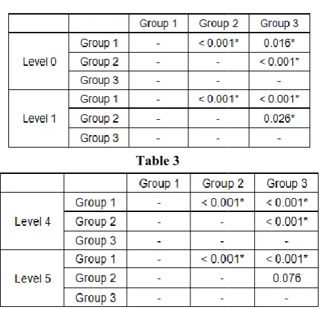
Intra group analysis showed that, all instruments promoted some deviation in virtually all levels. This was evaluated by comparing the difference of pre and post instrumentation images, between the mesial and distal sides at each measuring points. (Table 1& 2)
regardless of the group, more deviations were observed in the distal wall than the mesial wall.
Statistically significant difference was observed between group A and group B and between group A and group C at all levels of all the canals except that at level 6 no statistically significant difference was observed between group A and group C. (Table3 and 4)
In group A, the mean values of differences between mesial and distal measurements at levels 0 and level 7 were less than that of samples of group B but more than that of group C. At level 2 and level 6 the mean difference was less than both t groups; group B and group C. In group B, the values of mean differences between mesial and distal measurements of canals were more than that of group C at all levels except level 1 but less than group A at levels 1, 3, 4, 5.In group C, the minimum difference between mesial and distal measurements was observed at 5 levels (level 0, level 3, level 4, level 5 and level 7). At level 1, the difference was more than group B but less than group A. At level 2 and level 6 the difference was more than group A but less than group B. The values of mean difference were statistically significant at all these levels except level 5 and level 7.
Comparative analysis between experimental groups was done by using Tukey’s test. Statistically significant
observed within all the groups almost at all the levels. (Table 2 to Table 4)
Table 1 Pair wise one way ANOVA; Descriptive statistics showing the mean of differences between mesial and
distal measurements of pre and post-instrumentation images
Level
Difference between mesial and distal measurements Group A (n=15) Group B(n=15) Group C(n=15)
Mean SD Mean SD Mean
Level 0 0.080 0.029 0.329 0.011 0.060
Level 1 0.386 0.082 0.217 0.047 0.270
Level 2 0.239 0.062 0.969 0.010 0.428
Level 3 0.869 0.130 0.525 0.007 0.267
Level 4 0.836 0.049 0.552 0.016 0.262
Level 5 0.599 0.078 0.454 0.006 0.441
Level 6 0.153 0.050 1.137 0.010 0.165
Level 7 0.297 0.079 1.522 0.008 0.208
Table 2
Table 3
regardless of the group, more deviations were observed in the
Statistically significant difference was observed between group A and group B and between group A and group C at all levels of all the canals except that at level 6 no statistically significant difference was observed between group A and
In group A, the mean values of differences between mesial and distal measurements at levels 0 and level 7 were less than that of samples of group B but more than that of group C. At level 2 and level 6 the mean difference was less than both the In group B, the values of mean differences between mesial and distal measurements of canals were more than that of group C at all levels except level 1 but In group C, the minimum rence between mesial and distal measurements was observed at 5 levels (level 0, level 3, level 4, level 5 and level 7). At level 1, the difference was more than group B but less than group A. At level 2 and level 6 the difference was more less than group B. The values of mean difference were statistically significant at all these levels
Comparative analysis between experimental groups was done by using Tukey’s test. Statistically significant difference was observed within all the groups almost at all the levels. (Table 2
The Bar Diagram showing the mean of differences in the mesial and distal measurements of pre and post instrumentation images of the canals
DISCUSSION
Root canal preparation remains one of the most difficult tasks in endodontic therapy. The intrinsic anatomy of the root canal system creates challenges, emphasizing the necessity of proper disinfection measures. Isthmuses, inter
curvatures and oval shaped canals can make disinfection a considerable challenge.10 Canal scouting and pre
the first phases of canal instrumentation during which the clinician might more frequently encounter procedural difficulties.1
Maintenance of the multi-planar geometries of the original root canal anatomy facilitates the vectors needed for three dimensional sealing of the root canal system which is a prerequisite for successful endodontic therapy.
canals achieving a tapered preparation large enough for the exchange of irrigants, while maintaining the position of the apical foramen, can be precarious. The risk of creating ledges, perforations and zipping of the apex, as well as file separation, increases in curved canals. Since most teeth have root canals with single curves and some with multi
of iatrogenic errors is ever present during initial negotiation of the canals.12
The rationale of endodontics requires is the entire length of t root canal system be cleaned and shaped. Glidepath is pre requisite to this mechanical objective.
achieved when the file forming it can enter from the orifice and follow the smooth canal walls uninterrupted to the terminus.14
A glide path is defined as a smooth, though possibly narrow, tunnel or passage from the orifice of the canal to the radiographic terminus or electronic portal of exit (West 2006)15. The maintenance of a glide path means having a
0.000 0.200 0.400 0.600 0.800 1.000 1.200 1.400 1.600 Level 0 Level 1 Level 2 Level 3 Level M ean .. .. . Axis Title Mean ...
Pair wise one way ANOVA; Descriptive statistics showing the mean of differences between mesial and
instrumentation
Difference between mesial and distal
P value Group
C(n=15)
Mean SD
0.060 0.004 <0.001
0.270 0.005 <0.001
0.428 0.004 <0.001
0.267 0.010 <0.001
0.262 0.005 <0.001
0.441 0.026 <0.001
0.165 0.015 <0.001
0.208 0.004 <0.001
Table 4
The Bar Diagram showing the mean of differences in the mesial and distal measurements of pre and
post-he canals
Root canal preparation remains one of the most difficult tasks in endodontic therapy. The intrinsic anatomy of the root canal system creates challenges, emphasizing the necessity of proper disinfection measures. Isthmuses, inter-canal communications, curvatures and oval shaped canals can make disinfection a Canal scouting and pre-flaring are the first phases of canal instrumentation during which the clinician might more frequently encounter procedural
planar geometries of the original root canal anatomy facilitates the vectors needed for three dimensional sealing of the root canal system which is a prerequisite for successful endodontic therapy.11 In curved hieving a tapered preparation large enough for the exchange of irrigants, while maintaining the position of the apical foramen, can be precarious. The risk of creating ledges, perforations and zipping of the apex, as well as file separation, urved canals. Since most teeth have root canals with single curves and some with multi-planar curves, the risk of iatrogenic errors is ever present during initial negotiation of
The rationale of endodontics requires is the entire length of the root canal system be cleaned and shaped. Glidepath is pre requisite to this mechanical objective.13 A glide path is achieved when the file forming it can enter from the orifice and follow the smooth canal walls uninterrupted to the
path is defined as a smooth, though possibly narrow, tunnel or passage from the orifice of the canal to the radiographic terminus or electronic portal of exit (West . The maintenance of a glide path means having a
International Journal Of Current Medical And Pharmaceutical Research, Vol. 4, Issue, 9(A), pp. 3696-3702, September, 2018
smooth passage that is reproducible by successive files used in the canal (Khatavkar and Hegde, 2010)16.
Glidepath creation is essential for prevention of rotary file separation and most effective rotary use. A glidepath helps prevent torque failure and cyclic fatigue. Initially, when rotary files were introduced there was no recommendation for glide path creation. Subsequently, instrument fracture became a significant issue until glide path creation became known as an adjunct to safe rotary use. A glide path is now recommended by virtually all manufacturers of rotary nickel titanium files. Without a glidepath, rotary files can easily screw themselves into canals by engaging more dentin than ideal and separate. The glide path assures the operator that the tip of the file will not become locked as it moves apically and that the canal is free and clear of significant debris and blockage, could lead to iatrogenic events.7
Various instrument systems are recommended for Glide Path preparation such as K- Files, PathFiles, C + files, G –files, C- Pilot files, SafeSiders, C files, V-files, Hi-5 Files, PreShaper, Pathfinders TM CS, EndoWave, PathfindersTM, SenseusProfinders, K-Finders, S-Finders, D-Finders.7
Various studies have been conducted to evaluate the efficacy of different instrument systems in creating the glidepath and the incidence of deviation in the glidepath with these instruments.
Several authorshave recommended using stainless steel K-files by hand for preparing the glide path (Berutti et al, 2004; Gambarini, 2005; Ruddle, 2005; West, 2006; Mounce, 2005). 7
SafeSiders were developed to negotiate curved canals with as little resistance as possible. This means that the instruments require far less hand pressure allowing them to be used many more times than conventional instruments without distortion and replacement. It also means that the canals themselves are subject to far less distortional stresses facilitating the greater tapered shaping associated with superior instrumentation.8 The flat-sided design of the EZ-Fill SafeSider reamers derives from the understanding that a reamer design is significantly better than a file design because it engages less dentin. Consequently, a relieved SafeSider designed reamer must be significantly better than a conventional reamer because it engages even less dentin at any one time and also has a thinner cross sectional area making it more flexible.8
PathFileNiTi rotary files (Dentsply/Maillefer) were introduced to the market in 2009 specifically for the purpose of glide path enlargement. The system consists of three instruments which are available in 21mm, 25mm, and 31mm lengths. They have constant pitch between the flutes, a square cross section and a 2% taper, which makes them resistant to cyclic fatigue, ensures flexibility and improves cutting efficiency. The tip angle is 50 degrees and is non-cutting, which reduces the risk of ledge formation. PathFile No.1 (purple) has an ISO 13 tip size, PathFile No.2 (white) has an ISO 16 tip size and PathFile No.3 (yellow) has an ISO 19 tip size. The gradual increase in tip size facilitates progression of the files.18
Hence this in-vitro study was aimed to compare three different instrument systems, to evaluate their potential in creating glidepath in simulated curved canals and to analyze the incidence of deviation in the glidepath with these instrument systems. The instrument systems evaluated are: stainless steel
hand K-files; stainless steel hand SafeSider files and NiTi rotary PathFiles.
In the present study, 45 ISO #15, 0.02-tapered, curved Endo Training Blocks (DentsplyMaillefer) were used and the deviation in the canal anatomy after experiment with tested instruments systems was observed under the steriomicroscope.
Results revealed that, all instruments promoted some deviation in virtually all levels and there was statistically significant difference in the mean values of difference between mesial and distal plane of the canal, at all the levels (0-7) in all three experimental groups. Overall, regardless of the group, more deviations were observed in the distal wall than the mesial wall. The distal wall corresponds to the outer wall of the curvature and so all the instruments must have removed resin easily and unevenly, resulting in more deviation.
Statistically significant difference was observed between group A and group B and between group A and group C at all levels of all the canals except that at level 6 no statistically significant difference was observed between group A and group C. The mean values of differences between mesial and distal measurements at levels 0 and level 7 were less than that of samples treated with SafeSider instrument system but more than that of PathFile system. At level 2 and level 6 the mean difference was less than both the groups; group B and group C. This indicates that, stainless steel K-file instruments prepared glidepath better than SafeSider and PathFile instrument systems only at 2 levels but they caused more deviation in glidepath preparation.
The reason for more deviation in glidepath observed in the canals treated with stainless steel files could be because of the flute design of the K-files. The K-files are designed to have more number of flutes which act like a screw.
When the flutes are more or less in the same plane as the motion, the flutes tend to screw in under pure rotation. Under these circumstances, the flutes are more like a screw, which is defined as engaging without cutting, a definition that makes for a very inefficient endodontic tool when the goal is to remove axial tooth structure without causing deviation in the original canal anatomy.
Another reason for deviation with stainless steel K-files could be the size of last file used for glidepath preparation. We used #20 K-file as the last file, which is less flexible. The rigidity of #15 and #20 file may be responsible for the deviation resulted in the glidepath.
In group B (SafeSiders), the values of mean differences between mesial and distal measurements of canals were more than that of group C at all levels except level 1 but less than group A at level 1, 3, 4, 5. This means the SafeSider reamers maintain the original canal anatomy better than stainless steel files.
The reasons for the lesser deviation than stainless steel K-files, in the glidepath, using the SafeSiders/Endo-Express reciprocating hand piece in curved canals can be explained as:
motion used is rotation or reciprocation (short rotation).19
2. Less resistance or more efficient cutting along length, combined with a more flexible shaft with a cutting tip that can pierce rather than impact dentinal debris, produces a significantly better tactile awareness than the far more engaging k-files. Superior tactile awareness gives the dentist the ability to distinguish between a blocked canal and a tight one. Knowing the difference gives the dentist the chance to pre-bend and probe for proper patency along an abruptly curved canal. The stainless steel material of these reamers records the curvatures and gives valuable information on the degree, location and orientation of any curve the reamers encountered.19
3. Stainless steel K-Files encounter far greater resistance because they are tightly twisted square wires that make 4 point contact with every flute. Reamers, on the other hand, are loosely twisted triangular wires that make 3 point contact with every flute. Each flute on a reamer makes less contact than a file and there are about one half the number of flutes. As a result, reamers instrument canals with less hand fatigue, less distorted canals and less distorted instruments.8
Thus the relieved flat flutes, lesser number of flutes as compared to K-files, flexible shaft of the instrument, better tactile sensation and the ability to record and maintain the curvature of the canal may be the contributing features of SafeSider reamers in maintaining the original anatomy of the canal better than that with the stainless steel K-files.
In group C (Path files), the minimum difference between mesial and distal measurements was observed at 5 levels (level 0, level 3, level 4, level 5 and level 7). At level 1, the difference was more than group B (SafeSider) but less than group A (stainless steel K-file). At level 2 and level 6 the difference was more than group B but less than group A. The values of mean difference were statistically significant at all these levels except level 5 and level 7. From this we conclude that, the PathFile instruments system results in minimum deviation during glidepath preparation.
PathFile instruments are rotary NiTi instrument with highest resistance to cyclic fatigue. The NiTi alloy offers super-elasticity to the PathFiles. Hence, the reason for superior performance of the PathFiles might be related to increase flexibility to the instruments.
Natasha C.C. Ajuz, Luciana Armada et al conducted a study in which they compared the incidence of deviation along S-shaped (double curved) canals after glide path preparation with 2 nickel-titanium (NiTi) rotary path finding instruments and hand K-files. The results showed that all instruments promoted some deviation in virtually all levels. Both rotary NiTi instruments performed significantly better than hand K-files at all levels (P < .05).8
Elio Berutti, Giuseppe Cantatore et al compared changes to canal curvature and incidence of canal aberrations after preflaring with hand K-files or with nickel-titanium rotary PathFile in S-shape Endo Training Blocks. One hundred training blocks were colored with ink, and pre-instrumentation images were acquired digitally. Pre-flaring was performed PathFile (group 1) and hand stainless steel K-files #10-15-20 (group 2); Pre-instrumentation and post-instrumentation
images were superimposed to evaluate the outcomes investigated. Differences in canal curvature modification and incidence of canal aberration were analyzed with the Kruskall- Wallis plus post hoc tests and by the Monte Carlo method, respectively, (P < .05). The PathFile groups demonstrated significantly less modification of curvature (P < .001) and fewer canal aberrations (P< .001).20
Vanessa de Oliveira Alves, Carlos Eduardo Da Silveira Vueno et al conducted an in-vitro study. In their study, micro-CT scanning was used to compare the ability of manual and mechanical glide path to maintain the original root canal anatomy. The authors concluded that Micro-CT scanning confirmed that NiTi rotary PathFile instruments preserve the original canal anatomy and cause less canal aberrations.21
The results of our study are in accordance with above mentioned studies.6,20,21 Even in our study, the PathFile instruments caused less deviation in glidepath preparation, thus maintaining the original canal anatomy.
It becomes apparently clear from this study that the use of stainless steel hand instruments of size larger than 10 should be reduced when a predictable and repeatable scouting can be obtained by using small stainless steel hand files (sizes 06, 08, and 10). A predictable glide path can be obtained safely and effectively with stainless steel SafeSider reamers and NiTi PathFiles instruments, which avoids the increased transportation reported for bigger and less flexible stainless steel instruments. The SafeSide reamers can prepare the glidepath better than stainless steel hand K-files but there are not many studies in the literature, hence we recommend to test these instruments in separate studies. Furthermore, because some root canal transportation has been reported for the tested NiTi rotary glide path instruments to a last size of 19, further studies should evaluate the possible influence of the use of smaller size for glide path instrument (ie, #10 or #15) before starting with the preferred preparation technique.
CONCLUSION
In conclusion, our findings suggest that rotary NiTi instruments are suitable for adequate glide path preparation because they promoted less deviation from the original canal anatomy when compared with hand-operated instruments. Of all the three instrument systems PathFiles showed an overall significantly better performance.
References
1. I Cassim, P van der Vyver. An in vitrocomparison of different techniques for glide path preparation. SADJ November 2015, Vol 70 no 10 p452 - p456.
2. R. Kakehashi, I. R. Syanley, aad R. J. Pitzgerabd, B.N. Bethesda. The effects of surgical exposures of dental pulps in germ-free and conventional laboratory rats. National Institute of Dental Research September 1965, Volume 30 no 3.
3. Gary D. Glassman and Kenneth S. Serota. A Predictable Protocol for the Biochemical Cleansing of the Root Canal System. ORAL HEATH MAG - Jul 2001. 4. G. Yared. Canal preparation using only one Ni-Ti rotary
instrument: preliminary Observations. International Endodontic Journal. 24 September 2007.
International Journal Of Current Medical And Pharmaceutical Research, Vol. 4, Issue, 9(A), pp. 3696-3702, September, 2018
Instruments: A Micro-computed Tomography Study. J Endod 2010; 36:703-707.
6. Natasha C.C. Ajuz, Luciana Armada, Lucio S. Gonc¸alves, Gilberto Debelian and Jose F. Siqueira. Glide Path Preparation in S-shaped Canals with Rotary Pathfinding Nickel-Titanium Instruments. J Endod 2013; 39:534-537.
7. Anil Dhingra, Neetika. Glide path in endodontics. ENDODONTOLOGY Volume: 26 Issue 1 June 2014. 8. Barry Lee Musikant. The Best Ways to Perform
EZ-Fill® safesider® Endodontics.
9. Elio Berutti, Giuseppe Cantatore, Arnaldo Castellucci, Giorgio Chiandussi, Francesco Pera, Giuseppe Migliaretti, and Damiano Pasqualini. Use of Nickel-Titanium Rotary pathfile to Create the Glide Path: Comparison With Manual Preflaring in Simulated Root Canals. J Endod 2009; 35:408-412.
10. Z Mohammadi, S Shalavi, H Jafarzadeh. The oval shaped root canal: A clinical review. SADJ June 2015, Vol 70, No. 5, page 200 -204.
11. Schilder H. Cleaning and shaping the root canal. Dent Clin North Am 1974, 18,269-296.
12. Vertucci FJ. Root canal morphology and its relationship to endodontic procedures. Endod J 2005, 10, 3-29. 13. Sebastian Burklein, Thomas Poschmann and Edgar
Schafer. Shaping Ability of Different Nickel-Titanium Systems in Simulated S-shaped Canals with and without Glide Path. J Endod 2014; 40:1231-1234.
14. Drs. Clifford J. Ruddle, Pierre Machtou and John D. West. Endodontic canal preparation: new innovations in glide path management and shaping canals. Dentistry today July 2014.
15. West J. Endodontic update. J Esthet Restor Dent 2006, 18,280-300.
16. Khatavkar RA, Hegde VS. Importance of patency in endodontics. Endodontology 2010, 22, 85-91.
17. Helio P. Lopes, Carlos N. Elias, Jose F. Siqueira, Renata G. Soares, Letıcia C. Souza, Julio C.M. Oliveira, Weber S.P. Lopes and Marcelo Mangelli. Mechanical Behavior of Pathfinding Endodontic Instruments. J Endod 2012; 38:1417-1421.
18. Berutti E, Cantatore G, Castellucci A, Chiandussi G, Pera F, Migliaretti G, Pasqualini D. Use of nickel-titanium rotary pathfile to create the glide path: comparison with manual preflaring in simulated root canals. J Endod 2009, 35,408-412.
19. Barry Lee Musikant and Allan S. Deutsch. Verifying the claims of the safesider shaping system. ENDO TRIBUNE U.S. Edition.
20. Maurizio D. Amario, Mario Baldi, Roberto Petricca, Francesco De Angelis, Rashid El Abed and Camillo D. Arcangelo. Evaluation of a New Nickel-Titanium System to Create the Glide Path in Root Canal Preparation of Curved Canals. J Endod 2013; 39:1581-1584.
21. Damiano Pasqualini, Caterina Chiara Bianchi, Davide Salvatore Paolino, Lucia Mancini, Andrea Cemenasco, Giuseppe Cantatore, Arnaldo Castellucci and Elio Berutti. Computed Micro-Tomographic Evaluation of Glide Path with Nickel-Titanium Rotary pathfile in Maxillary First Molars Curved Canals. J Endod 2012; 38:389-393.
How to cite this article:
Tejonmayie S. Yedekar et al (2018) 'Comparative Evaluation of Deviation in the Glide Path Preparation in Curved Canals with Different Path Finding Instrument Systems- An in-Vitro Study', International Journal of Current Medical and Pharmaceutical Research, 04(9), pp. 3696-3702.