The Automotive Deployment Problem: A Practical Application for
Constrained Multiobjective Evolutionary Optimisation
Irene Moser,
Member, IEEE
and Sanaz Mostaghim,
Member, IEEE
Abstract— State-of-the art constrained multiobjective opti-misation methods are often explored and demonstrated with the help of function optimisation problems from these ac-counts. It is sometimes hard for practitioners to extract good approaches for practical problems. In this paper we apply an evolutionary algorithm to a factual problem with realistic constraints and compare the effects of different operators and constraint handling methods. We observe that in spite of an apparently very insular search space, we consistently obtain the best results when using a repair mechanism, effectively eliminating infeasible solutions. This runs contrary to some recommendations in the optimisation literature which propose penalty functions for search spaces where feasible solutions are sparse.
I. INTRODUCTION
The vast majority of publications on multiobjective optimi-sation using evolutionary algorithms (MOEA) illustrate their findings with experiments on well-known functions from the continuous domain. These functions are readily available and provide the researcher with a set of optimal solutions that form a pareto front whose shape and difficulty are known to the field. Practitioners who would like to benefit from the insights into optimiser properties are often faced with the need to solve a discrete practical (‘real-world’) problem. It is not always easy for such a practitioner to translate the findings gained from trials on continuous functions into methods that are well suited to practical problems.
One example of a non-trivial discrete optimisation problem is the software deployment problem [1], [2], which seeks solutions to the optimal deployment of control logic com-ponents in vehicles designed by the automotive industry. To benefit from the advantages of mass production, vehi-cles of the same type or series are often fitted with the same predesigned infrastructure of Electronic Control Units (ECUs) and data buses. ECUs are comprised of a processing unit (CPU) and a memory. The hardware infrastructure of a contemporary car usually consists of approx. 50–80 ECUs, each of which is connected to one of the 3–5 data buses. Software components which control different aspects of functionality of a vehicle can be assigned to many different ECUs subject to memory requirements, processing power and similar restrictions.
The software deployment problem is multi-faceted in the sense that there are many different objective functions to
Irene Moser is with the Faculty of Information and Communication Tech-nologies, Swinburne University of Technology, Hawthorn 3122, Australia (phone: +61 3 9214 4745; email: [email protected] ).
Sanaz Mostaghim is with the Karlsruhe Institute of Technology (KIT), 76128 Karlsruhe, Germany (phone: +49 721 6086554; email: [email protected]).
optimise, some of which are partly correlated. Also, many different constraint formulations exist. These arise from the variations in the way different car manufacturers approach the problem. It is possible, for example, to optimise the hardware infrastructure in the same optimisation process. However, the infrastructure is usually fixed over a period of time. Vehicles typically retain their hardware layout until a new series is launched. A similar problem to the software deployment problem is known as redundancy allocation [3], [4], [5], where the goal is to introduce redundant ECUs fulfilling identical functions to increase the reliability of the system.
In this paper, we optimise the software deployment prob-lem as a biobjective formulation with the reliability of data communications between components as one and the com-munications overhead as a second objective. The problem is highly constrained by the limitations of ECU choices each component has, the memory constraints that have to be observed when allocating components to the same ECUs, as well as prescribed colocation (a component has to reside on the same ECU) or precluded colocation (a component must not reside on the same ECU as another). In this paper, we apply some of the findings of long-term research into multiobjective optimisation and constraint handling to this discrete practical problem and compare their performance in a realistic domain.
II. PROBLEMDESCRIPTION
The software deployment problem described here rep-resents one aspect of the optimisation task of allocating the software components which provide the control logic for contemporary vehicles (e.g. ABS and airbag control functions). This optimisation task is based on the fact that due to the benefits of mass production, many types of cars are fitted with the same hardware infrastructure. The necessary software functionality is represented by a predefined set of software components, which have to be deployed to the ECUs. A solution to the software deployment problem is the mapping of all available software componentsC to all or a subset of all ECUsU di={(c1, ui1),(c2, ui2), ...,(cn, uim)}, wherei1toinare integers in[1...m]. The set of all possible
solutions is D = {d | d : C → U}. More in-depth description of the problem and its aspects is found in [6], [3], [7].
A. Hardware Infrastructure
The ECUs are connected to different data buses and vary in memory capacity, processing power and failure propensity. WCCI 2010 IEEE World Congress on Computational Intelligence
Some ECUs provide sensor access. The data buses are characterised by different data rates and degrees of reliability. The speed and reliability of communication between two ECUs therefore depends on the data buses they are connected to.
More formally, the hardware architecture is defined in the following terms:
• The set of available ECUs U ={u1, u2, ..., um},m∈ N;
• ECU capacity, cp:U →N;
• ECU processing speed, ps:U →N; • ECU failure rate, fr:U →R;
• data rate of the preferred bus, dr:U ×U →N; • network delay, nd:U×CU →R;
• reliability of the preferred bus, rel:U×U →R.
B. Software
The optimisation task is to allocate a number of predefined software components to the ECUs in the existing hardware infrastructure. Each software component fulfils a predefined function in the vehicle. The component has a memory requirement (denoted by the component size) and is subject to restrictions such as location and colocation. The location restriction defines the set of possible ECU allocations for this component. It reflects the fact that some functions require features only certain ECUs provide (such as a connection to a sensor). Some components need to communicate with some other components and cannot rely on the data bus for sufficient speed, hence they need to reside on the same ECU. The constraints are explained in more detail in II-D.
• The set of components,C={c1, c2, ..., cn},n∈N; • component size, sz:C→N;
• location restriction, lr:C→ P(U);
• colocation restriction, coloc:C×C→1,−1; • data size sent over a link, ds:C×C×S→R; • frequency of communication between two components,
freq:C×C→R;
• the communication link between two componentsiand j,lij= (ci, cj).
C. Objective Functions
As a specific setting for our algorithms, two non-functional quality attributes are considered, i.e. Data Transmission Re-liability (DTR) as defined by Malek [8] and Communication Overhead (CO) following Medvidovic and Malek [1]. Three constraints are included, memory constraint, location and colocation constraints.
Reliability of the data transmission is a crucial quality attribute in a real-time embedded system, where important decisions are taken based on the data transmitted through the communication links. For example, timely activation of the air-bag system in a car is highly dependent on the reliability of the data link from the crash detection sensor to the responsible ECU and from the ECU to the airbag firing unit. This deployment-dependent metric represents to what extent the total data transmission for a given architecture is
reliable. Maximum values for the DTR often take precedence in deployment architecture decisions. The Data Transmission Reliability (DTR) formulation we use has first been defined by Malek [8]. fDT R(d) = n X i=1 n X j=1 freq(ci, cj)·rel(d(ci), d(cj)) (1)
Moreover, in an embedded system, where computation and energy resources are highly constrained, sophisticated data recovery mechanisms, like re-transmission, are discouraged. The deployment architecture should be determined by min-imising the overhead enforced by the data communication for a given set of system parameters. As a network- and deployment-dependent metric, the overall communication overhead of the system is used to quantify this aspect. It was first formalised by Medvidovic and Malek [1].
fCO(d) = n X i=1 n X j=1 freq(ci, cj)·nd(d(ci), d(cj))+ + n X i=1 n X j=1 freq(ci, cj)·ds(ci, cj) dr(d(ci), d(cj))·rel(d(ci), d(cj)) (2) D. Constraints
Not all deployment candidates d ∈ D represent feasible alternatives. Placing many components onto a single ECU is often desirable, as it leads to faster communication be-tween the colocated components. However, the number of components to be placed on a single ECU is restricted by the memory size of the ECU and the memory requirements of the component. In analogy with the traditional bin packing problem, the memory constraintΩmemis defined as follows:
Ωmem(d) = ∀u∈U :
X
i∈d(ci)=uj
sz(ci) ≤ cp(uj) (3)
The location constraintΩloc excludes certain components
from residing on particular ECUs:
Ωloc(d) =∀c∈C: (u∈lr(c) ⇒ d(c)6=u) (4)
The colocation constraint Ωcoloc excludes certain
compo-nents from residing on particular ECUs:
Ωcoloc(d) =∀c∈C: (ci, cj∈coloc−1 ⇒ d(ci)6=d(cj)) ∀c∈C: (ci, cj ∈coloc1 ⇒ d(ci) =d(cj))
(5) All of the constraints Ω are hard constraints in the sense that a solutions which violate them cannot be considered for implementation. It is therefore meaningful to consider them separately from the objective functions.
III. ALGORITHMICAPPROACH
The Nondominated Sorting Genetic Algorithm (NSGA) in its improved form NSGA-II by Srinivas and Deb [9] is recognised as one of the most successful state-of-the art mul-tiobjective problem solvers. Strong alternatives include the Strength Pareto Evolutionary Algorithm (SPEA2) by Zitzler et al. [10] as well as Knowles and Corne’s Pareto Archived Evolution Strategy (PAES) [11]. Third-party comparisons of these approaches appear inconclusive [12]. Moreover, every algorithm takes a different approach to reducing the number of solutions retained as a diversity mechanism. Comparisons including this feature might not be directly applicable to the automotive software deployment problem. Unlike appli-cations to continous space, where the number of solutions in the nondominated set is potentially infinite, the software deployment problem has many constraints and is unlikely to produce more solutions than the optimiser can use for the improvement of the approximation sets.
NSGA-II was used as a basis for the implementation of the optimiser for the automotive software deployment problem. Having omitted the crowding method NSGA-II uses to ensure diversity in the population, the remaining discerning characteristic of the algorithm is its nondominated ranking scheme. It is non-parametric in the sense that only the dominance rank of a solution defines its ‘fitness’.
Once the relevant genetic operators have been applied and the child population has been added to the current (parent) population, all solutions are divided into successive nondominated fronts, which determine the ranks of the solutions. Starting from the lowest ranks, the population is then reduced to the predefined population size. Deb [13] provides a comprehensive explanation of the algorithm. A. Constraints
One of the major challenges of the software deployment problem is how to handle its numerous constraints ade-quately. The degree of constrainedness of the problem space can be illustrated by the fact that creating 10 million random deployments did not produce a single feasible solution, even after omitting the colocation constraint. As Deb [13] clarifies, when few feasible solutions are present (the search space consists of ‘islands’ of feasibility) the likelihood of finding feasible solutions without traversing the infeasible space is improbable. The experiments published by Woldesenbet, Yen and Tessema [14] support this theory.
Michalewicz and Schoenauer [15] categorised the existing approaches to constraint handling into penalty methods, methods which preserve feasibility, methods which distin-guish between feasible and infeasible solutions and methods which repair solutions. One might argue that if solutions are discarded after a failed repair procedure, this approach can also be counted among the feasibilty preservation methods.
The feature model approach applied by Limbourg and Kochs [16] on the related redundancy allocation problem falls into the category of feasibility preservation. The authors weigh the need to constrain the search space to meaningful
areas against the risk of precluding the creation of poten-tially desirable solutions. The resulting feature model builds solutions based on trees of possible component assignments, excluding non-feasible moves.
A similar search space reduction is meaningful in the case of software deployment. The assignment options provided for each component in the instance’s location list, equation (4), are a hard constraint which cannot be violated. If the genetic operators provide the possibility of transforming one feasible solution with one component-ECU allocation, e.g. d(ci, uj)
to another possible allocation d(ci, uk)without barriers
be-tween the solution, ergodicity is ensured. Another reason to choose this approach is the difficulty of quantifying possible location violations for penalty functions.
As the same reasons apply to the colocation restrictions (equation (5)), our approach deals with both constraints using feasibility preservation. The genetic operators change allo-cations subject to their feasibility according to equations (4) and (5).
Memory constraint violations can easily be quantified. Looking to investigating the experience of Deb and oth-ers [13], [14] regarding the effects of different memory handling methods on the search space, we decided to imple-ment the memory constraint (equation (3)) handling in three different ways according to the classifications of Michalewicz and Schoenauer [15].
1) Constrain-dominance for memory violation: For the strategy of handling feasible and infeasible solutions sep-arately we chose the implementation suggested by Deb [17], [13], and favoured by many authors. Constrain-dominated sorting is used as a solution comparison during NSGA-II’s nondominated ranking of the successive fronts. If both solutions are feasible, the usual dominance relationship holds where a solution is dominated by another solution if it is worse than that solution in at least one of the objectives. Feasible solutions always dominated unfeasible solutions and an unfeasible solution dominates another unfeasible solution if its constraint violation is smaller.
2) Repairing memory violations: Our approach to repair-ing individuals which violate the memory constraint can be seen as feasibilty preservation. If an offspring cannot be repaired using the repair algorithm, it is discarded.
It is clear that this approach is not guaranteed to repair a solution. Depending on the number of components that cannot be allocated to the same ECU (the colocation con-straint), and the average memory capacity, reassignments may not be possible without shifting other components first. Solutions created randomly for the initial population are subjected to the repair function and discarded if it fails. The same principle applies to offspring created using the genetic operators. Therefore, the entire population is always feasible when we use this strategy.
3) Penalising memory violation: The third strategy is to apply a penalty function. One of the more recent propositions to formulate a penalty function was conceived by Woldesen-bet et al. [14]. It is based on the concept of the infeasible individual’s distance to the feasible region, expressed by
Algorithm 1:Repair Function
foreachECUui that has allocations in excess of
memory capacitydo
whileECUui capacity exceeded do
foreachComponentcj assigned to the ECUui
do
foreachECUuk incj’s list of ECU options
do
ifuk has enough memory and has no
component that conflicts withcj then
assign d(cj, uk); remove assignmentd(cj, ui); break; di(x) = ( v(x), ifrf = 0 q ˜ fi(x)2+v(x)2, otherwise (6)
Here, rf stands for the proportion of feasible solutions
(|feasiblesolutions|population| |),f˜i(x) represents a normalised objective
value and v(x) is the (normalised) quantifier of constraint violation. To obtain the adjusted objective function value Fi(x)we use
Fi(x) =di(x) +pi(x) (7)
The penalty valuepi(x)is calculated:
pi(x) = (1−rf)Xi(x) +rfYi(x) (8)
where Xi(x) is v(x) (the quantified memory violation)
if there are feasible individuals in the population, zero otherwise. Feasible individuals have a Yi(x) of f˜i(x) (the
normalised objective function result for the respective objec-tive), for infeasible individualsYi(x)is zero.
This formulation ensures that when there are no feasible solutions, the solutions are compared solely according to their constraint violations, whereas in the absence of infea-sible solutions, the objective function values are compared. When both are present, the importance of the objective func-tion grows with the number of feasible individuals, whereas the significance of the constraint violation declines. The only conceivable drawback of the method is the weighting of the constraint violation against different objective functions.
˜
fi(x) = max(ffi(x)−min(fi(x))
i(x))−min(fi(x)) (9)
Although all values are normalised according to equa-tion (9), the fluctuaequa-tions of fitness values in an average population will vary. Hence there may be differences in the treatment of the objectives in this approach. Also, some ad-justments had to be made to accommodate the maximisation of objectives.
B. Solution Representation
The representation or genotype of an individual population member has some influence on the genetic operators that can conveniently be implemented. The most prevalent representation with GAs is binary encoding, which is convenient -though not well suited for real numbers’ [18]. In the case of the software deployment problem, binary representation is not meaningful. The most obvious options include a mapping from components to ECUs and a mapping from ECUs to components.
Our experiments compare two representations. The first, component-based, is a list of length nwhere each item rep-resents a component which maps to the ECU it is currently allocated to. The second, ecu-based, is a list of lengthm in which the ECUs are mapped to a list of components which are currently allocated to this ECU. The list may contain 0−mmembers. (If a non-dominated solution contains ECUs with no allocated components, we may have identified a potential for reducing the number of ECUs in the future.) C. Operators
Two mutation and one crossover operators have been im-plemented on both representations. In practice, the mutation operators will provide the same neighbourhood regardless of representation, while there is a clear distinction in the implementation of the crossover operator depending on the representation. All but the crossover operator for ECU-based representation are standard well-known implementations of genetic operators. For a detailed discussion of all typical crossover operators and their effects see [19].
1) Point Mutation: A random assigned component is chosen to be reassigned to a randomly determined new ECU from the component’s lr list of permissible ECUs. Due to colocation constraints (coloc−1), some ECUs cannot be
assigned due to other existing allocations. While unable to assign, the algorithm first repeatedly picks alternative ECUs. If none of the ECUs can be allocated because of colocation restrictions, the method randomly picks another component. The number of attempts in all cases is twice the number of choices. This should guarantee that most attempts try every possible combination before abandoning. Point mutation will only reassign a component that has no group members.
2) Swap Mutation: As with point mutation, the method makes a number of attempts equivalent to twice the number of options to find components to reassign. Unlike point mutation, the swap mutation operator also chooses a second component whose ECU assignment can be swapped with the first choice without violating the location and colocation constraints. Rather than abandoning the choice when a com-ponent is found to be part of acoloc1group, swap mutations
transfers all members of the same group onto the new ECU, subject to location and colocation (coloc−1) restrictions.
Swap mutation has the same effect on the solution regardless of the representation.
3) Crossover: The implementations of the crossover op-erator differ significantly depending on the chosen represen-tation. In the case of the component-based representation we
use single-point crossover between two parents. When cross-ing over, we do not need to check the location constraint, as we swap only possible allocations.
Algorithm 2:Crossover - Component-Based Rep. endiffortwice the number of components 2∗ndo
crIndex = random(1...n); fori = crIndex;i < n do
ifcparenti 1 ORcparenti 2∈coloc1 then
ifother group members assigned AND no coloc violationthen
assign to same ECU;
else ifswapdi(c)parent1 ANDdi(c)parent2
== no coloc violation; then
swapdi(c)parent1 anddi(c)parent2;
then
ifprevious assignments di(c)parent1 and
di(c)parent2 == no coloc violation then
keep previous assignments ; then
restart; ifstill no new solution then
throw exception;
The ECU-based representation conveniently enables the use of a custom crossover operator which combines the component lists of both parents for every ECU. The list’s content can then be distributed to the same ECU in the two offspring. The location constraint will naturally be fulfilled (as the ECU allocations are always maintained), whereas colocation constraints must still be imposed. We are not aware of previous implementations of this operator.
IV. EXPERIMENTS A. Problem Instances
For our experiments, two sets of problem instances were created, a problem with 35 ECUs and 60 components and a larger instance featuring 80 ECUs and 140 components. There are two versions of both, one with colocation con-straints (coloc1 andcoloc−1), the other omitting colocation
constraints, primarily to test the effects of the decision to pre-clude the occurrence of infeasible individuals with respect to the colocation constraint. Where colocation constraints were applied, 2% of the components were randomly chosen to be incompatible (coloc−1), whereas the groups of components
that have to reside on the same ECU are usually of size 2 - 4. Approximately 40% of the components belong to a group. This is representative of a vehicle software design, where some components cooperate, which entails a need for instant communication, which is not possible over a data bus. Each component can be allocated to approximately 20% of the available hosts.
Algorithm 3:Crossover - ECU-Based Representation Data: parent1 lst, parent2 lst
Result: offspring1 lst and offspring2 lst
Create list ecu lst of length mand fill with empty lists; fori 0;
i < m do
fill ecu lst[i] with components from parent1 lst[i] and parent2 lst[i];
forrestarts <2∗ndo fori=0; i < m do forj=0; j<ecu lst[i].length do if cj ∈coloc1 ORcj ∈coloc−1 ORcj is
duplicate in ecu lst[i]then
if assignment to offspring1 lst[i] or offspring2 lst[i] can be made without violation then
Assigncj to offspring1 lst[i] or
offspring2 lst[i]; else
restart; else
With 50% probability addcj from
ecu lst[i] to offspring1 lst[i], alternatively to offspring2 lst[i]; if still no new solutionthen
throw exception;
B. Algorithmic Settings
In our trials, we used a mutation rate of 0.2, which is divided evenly between point and swap mutation. The crossover rate was set to 1. All trials were repeated 30 times with different random seeds. Every trial was allowed 200 generations. The regeneration rate (number of offspring) was set to 0.9, i.e. 90% of the parent population, which was set to 50 individuals. The three approaches to constraint handling were combined with the two representations, resulting in 6 trial series per problem instance.
C. Performance Metrics
Summary attainment surfaces [20] were used to accu-mulate over the approximation sets over the 30 trials. The hypervolume development over the generations was also measured.
V. RESULTS
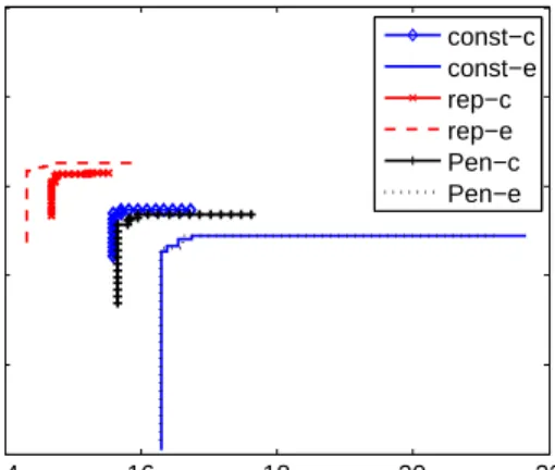
Figures 1 and 2 show the results for the problem instance C60 without considering the colocation constraint. U35-C60 refers to the problems instance containing 35 ECUs and 60 components. Between the two representations, ECU-based is shown to provide better results than the component-based representation. We observe this on all the results and
16 18 20 22 24 0.994 0.9945 0.995 0.9955 0.996 0.9965
35 ECUs and 60 components
fCO f DTR const−c const−e rep−c rep−e Pen−c Pen−e
Fig. 1. Average attainment surfaces for the problem instance U35-C60 without colocation constraint.
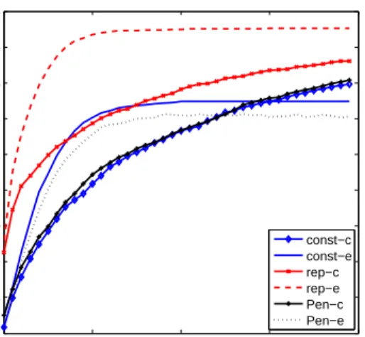
0 50 100 150 200 74 75 76 77 78 79 80 81 82 83 84 generation Average hypervolume const−c const−e rep−c rep−e Pen−c Pen−e
Fig. 2. Average hypervolume over generations for the problem instance U35-C60 without colocation constraint.
all the constraint handling techniques. Among the constraint handling methods, the repair mechanism obtains consider-ably better results than the other methods. This could be explained by the absence of the colocation constraint, which makes the problem similar to bin packing. For this problem, the repair mechanism is known to be a standard constraint handling technique [15].
The graphs also show that the constrain-dominance proach provides slightly better results than the penalty ap-proach. When comparing the effects of a change of rep-resentation, the results show that the ECU-based encoding consistently outperforms the component-based trials that use the same constraint-handling methods. Hence, the ECU-based representation combined with the repair mechanism produces the best results over all instances of the problem. This approach also provides superior solutions from the very start of the optimisation process, as shown in Figure 2. The same experiments have subsequently been carried out on a larger problem instance U80-C140, where we have 80 ECUs and 140 components. 120 130 140 150 160 0.9952 0.9954 0.9956 0.9958 0.996 0.9962 0.9964
80 ECUs and 140 components
f CO f DTR const−c const−e rep−c rep−e Pen−c Pen−e
Fig. 3. Average attainment surfaces for the problem instance U80-C140 without colocation constraint.
The encoding list of individuals is naturally much longer than that of the earlier problem instance. Figure 3 shows the average attainment surfaces for all combinations of constraint handling techniques and representations. As before, the ECU-based representation outperforms the other approaches.
‘Switching off’ the colocation constraint for the first experiments provides an opportunity to compare the algo-rithm’s behaviour on different degrees of constrainedness. Adding the colocation constraint, we specify in the problem instance’s definition that some components must be allocated to one ECU and others that must not be assigned together. The results are shown in Figures 4 and 5 for the problem instance U35-C60. The outcomes of the comparison between
14 16 18 20 22 0.9955 0.996 0.9965 0.997 0.9975 0.998
35 ECUs and 60 components
f CO f DTR const−c const−e rep−c rep−e Pen−c Pen−e
Fig. 4. Average attainment surfaces for the problem instance U35-C60 with colocation constraint.
the approaches here are very similar to those on the less con-strained problem. The ECU-based representation combined with the repair mechanism produces the best results from the early generations compared to other methods. Generally we can conclude that within the limits of 200 generations, the optimisations process produces the best results when us-ing the repair mechanism, followed by constrain-dominance
0 50 100 150 200 77 78 79 80 81 82 83 84 85 86 generation Average hypervolume const−c const−e rep−c rep−e Pen−c Pen−e
Fig. 5. Average hypervolume over generations for the problem instance U35-C60 with colocation constraint.
and penalty approaches. The comparison of the constrain-dominance and penalty approaches are inconclusive over different problem instances. Figures 2 and 5 also indicate that the component-based penalty and constrain-dominated algorithms may still improve at the time of the 200th gener-ation. The colocation constraint was subsequently applied to the larger problem instance U80-C140. Figure 6 shows very similar results to results in Figure 4 in terms of the ranking between the different approaches. This seems to indicate that, within a problem scale of 100 ECUs, the size of the search space does not seem to affect the behaviour of the algorithms, and the approaches presented in the paper behave the same when the problems have a colocation matrix.
70 75 80 85 90 0.9962 0.9964 0.9966 0.9968 0.997 0.9972 0.9974 0.9976
80 ECUs and 140 components
f CO f DTR const−c const−e rep−c rep−e Pen−c Pen−e
Fig. 6. Average attainment surfaces for the problem instance U80-C140 with colocation constraint.
VI. CONCLUSIONS
The results consistently indicate that the ECU-based rep-resentation facilitates the discovery of better solutions. Our interpretation ascribes this observation in part to the rel-ative shortness of the representation, which might make its complexity more manageable. The specialised crossover
operator undoubtedly contributes to shaping the search space favourably.
The consistent superiority of the repair approach to infea-sibility indicates that the infeasible areas are too large for traversal using penalty-based methods. The approximation sets obtained from the more constrained problem instances (when applying the colocation constraint) are significantly shorter regardless of the solver’s approach. An interesting topic for future research is how to explore ‘more’ islands of feasiblity in any one run.
REFERENCES
[1] N. Medvidovic and S. Malek, “Software deployment architecture and quality-of-service in pervasive environments,” in Workshop on the Engineering of Software Services for Pervasive Environements, ESSPE. ACM, 2007, pp. 47–51.
[2] S. Malek, “A user-centric approach for improving a distributed soft-ware system’s deployment architecture,” Ph.D. dissertation, Faculty of The Graduate School University Of Southern California, 2007. [3] L. Grunske, “Identifying ”good” architectural design alternatives with
multi-objective optimization strategies,” inInternational Conference on Software Engineering, ICSE. ACM, 2006, pp. 849–852. [4] Y.-C. Liang and A. E. Smith, “An ant system approach to redundancy
allocation,” inCongress on Evolutionary Computation. IEEE, 1999, pp. 1478–1484.
[5] D. W. Coit and A. E. Smith, “Reliability optimization of series-parallel systems using a genetic algorithm,”IEEE Transactions on Reliability, vol. 45, no. 2, pp. 254–260, 1996.
[6] A. Aleti, S. Bj¨ornander, L. Grunske, and I. Meedeniya, “ArcheOpterix: An extendable tool for architecture optimization of AADL models,” inModel-based Methodologies for Pervasive and Embedded Software (MOMPES). ACM and IEEE Digital Libraries, 2009, pp. 61–71. [7] L. Grunske, “Early quality prediction of component-based systems - A
generic framework,”Journal of Systems and Software, vol. 80, no. 5, pp. 678–686, 2007.
[8] S. Malek, “A user-centric approach for improving a distributed soft-ware systems deployment architecture,” PhD in Computer Science, Faculty of The Graduate School University of Southern California, 2007.
[9] K. Deb, A. Pratap, S. Agarwal, and T. Meyarivan, “A fast elitist multi-objective genetic algorithm: Nsga-ii,” IEEE Transactions on Evolutionary Computation, vol. 6, pp. 182–197, 2000.
[10] E. Zitzler, K. Giannakoglou, D. Tsahalis, J. Periaux, K. Papailiou, T. F. (eds, E. Z. Ler, M. Laumanns, and L. Thiele, “Spea2: Improving the strength pareto evolutionary algorithm for multiobjective optimiza-tion,” 2002.
[11] P. J. Angeline, Z. Michalewicz, M. Schoenauer, X. Yao, and A. Za-lzala, Eds.,The Pareto Archived Evolution Strategy: A New Baseline Algorithm for Pareto Multiobjective Optimisation, vol. 1. IEEE Press, June-September 1999.
[12] F. Mendoza, J. Bernal-Agustin, and J. Dominguez-Navarro, “Nsga and spea applied to multiobjective design of power distribution systems,” Power Systems, IEEE Transactions on, vol. 21, no. 4, pp. 1938–1945, Nov. 2006.
[13] K. Deb,Multi-Objective Optimization Using Evolutionary Algorithms, 1st ed. Wiley, June 2001.
[14] Y. G. Woldesenbet, G. G. Yen, and B. G. Tessema, “Constraint handling in multiobjective evolutionary optimization,” Trans. Evol. Comp, vol. 13, no. 3, pp. 514–525, 2009.
[15] Z. Michalewicz and M. Schoenauer, “Evolutionary algorithms for constrained parameter optimization problems,”Evol. Comput., vol. 4, no. 1, pp. 1–32, 1996.
[16] P. Limbourg and H.-D. Kochs, “Multi-objective optimization of gen-eralized reliability design problems using feature models–a concept for early design stages,”Reliability Engineering and System Safety, vol. 93, no. 6, pp. 815 – 828, 2008.
[17] K. Deb, “An efficient constraint handling method for genetic algo-rithms,”Computer Methods in Applied Mechanics and Engineering, vol. 186, no. 2-4, pp. 311–338, June 2000.
[18] U. K. Chakraborty and C. Z. Janikow, “An analysis of gray versus binary encoding in genetic search,” Information Sciences, vol. 156, no. 3-4, pp. 253 – 269, 2003, evolutionary Computation. [On-line]. Available: http://www.sciencedirect.com/science/article/B6V0C-4950PV1-7/2/02c4d8f232005b267e2293d5933d92eb
[19] M. Randall, “A general modelling system and meta-heuristic based solver for combinatorial optimisation problems,” Ph.D. dissertation, Griffith University, 1999.
[20] J. Knowles, “A summary-attainment-surface plotting method for vi-sualizing the performance of stochastic multiobjective optimizers,” in ISDA ’05: Proceedings of the 5th International Conference on Intelligent Systems Design and Applications. Washington, DC, USA: IEEE Computer Society, 2005, pp. 552–557.