Page 1 of 30
NERVE CONDUCTION MANUAL
James W. Albers, M.D., Ph.D
Emeritus Professor of Neurology
Electroneuromyography Laboratory
Department of Physical Medicine and Rehabilitation
University of Michigan Hospital
Page 2 of 30
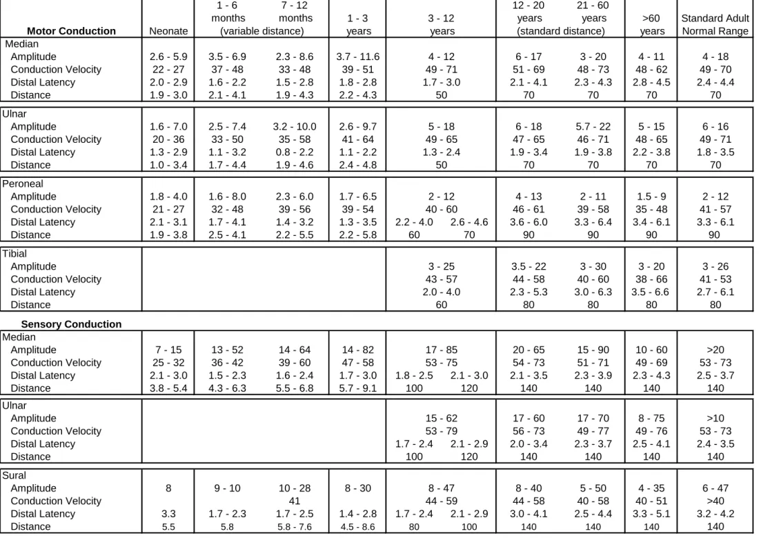
The normal values contained in the chart at the end of this manual (Table 1) for the
various nerves have been determined for use in this laboratory and may vary from one
laboratory to another. There are three parameters used in determining whether a conduction
study is normal or abnormal. These parameters are amplitude of the MUAP, latency of the
response, and conduction velocity.
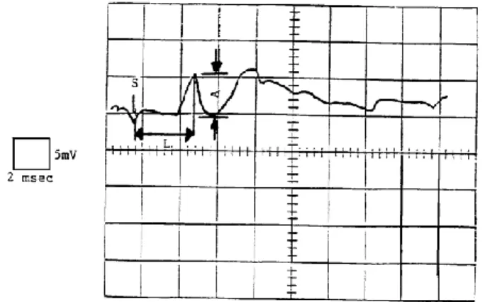
The motor amplitude represents the summation of the individual muscle fiber action
potentials within that muscle and correlates highly with the number of viable axons. The
amplitude is measured in millivolts from the baseline to the negative peak of the response
obtained from supramaximal nerve stimulation (
Figure 1
). Sensory amplitude (peak-to-peak) is
measured in microvolts and also correlates with the number of viable axons (
Figure 2
).
The latency refers to the elapsed time between the start of the stimulus and the onset
of the response. It represents the propagation of the impulse along the nerve, the transmission
across the end-plate, and the depolarization of the muscle fibers. The latency is measured in
milliseconds from the onset of the stimulus to the first negative deflection from the baseline in
motor conduction (
Figure 1
) and to the peak of the response in sensory conduction (
Figure 2
).
The conduction velocity is obtained by stimulating the nerve at two different points
along the nerve at least 10 cm apart. To calculate the conduction velocity, the difference
between the latencies’ onset obtained at the two points is divided by the distance between the
two points. It is calculated in meters per second.
Conduction velocity = ______ Distance (cm)______ X 10
Latency 2 – Latency 1 (msec)
There are a number of problems and pitfalls encountered in performing nerve
conduction studies. The most common pitfall occurs from incorrect measurement of nerve
length caused by one of the following:
1.
Stretching the skin while measuring
2.
Not following the course of the nerve
3.
Using a non-standard limb position
Other common errors include the following:
1.
Reversed polarity of the stimulating or recording electrodes
2.
Active recording electrode not over the motor point of the muscle
3.
Submaximal stimulation
4.
Skin temperature below 32
◦C
5.
Stimulus spread
Page 3 of 30
Another problem encountered in performing nerve conduction studies is artifact. The
most common types are:
1.
Stimulus artifact commonly caused by one of the following:
a.
Inadequate grounding
b.
High impedance of recording electrode contact with skin
c.
Inadvertent electrical connection between stimulating electrodes and
ground or recording electrodes
2.
60 Hz interference commonly caused by one of the following:
a.
Fluorescent light
b.
IVAC or other electrical equipment in contact with the patient
c.
Ungrounded wall outlet
3.
Movement artifact caused by poor patient relaxation
When any of these problems are encountered the cause should be found and
eliminated before proceeding with the nerve conduction study.
Figure 1. Motor responses recorded distally (top) and proximally (bottom). S represents the stimulus, L1 (distal) and L2 (proximal) represent the latencies of the responses, and A represents the amplitude.
Figure 2. Sensory response recorded distally. S represents the stimulus, L represents the latency of the response, and A represents the amplitude.
Page 4 of 30
Median Nerve – Course and Distribution
Diagram of the Course and Distribution of the Median Nerve.
The muscles supplied are
indicated in italics. In the hand the cutaneous branches are marked by stipple, as is also the
field of cutaneous innervation (see inset). The nerve indicated by 1 is the palmar cutaneous of
the median nerve; and those by 2, the palmar digital nerves. The corresponding areas of
cutaneous innervations are indicated in the inset. In some individuals the region of
innervations of the dorsal aspect of the fingers in somewhat more proximal than indicated in
this drawing.
Page 5 of 30
Median Motor Conduction
The active recording electrode is placed over the abductor pollicis brevis muscle as described
below. A line is drawn across the palmar aspect of the wrist crease (1). A second line is drawn
across the palmar surface of the first MCP joint at right angles to the axis of the first metacarpal
(2). A third line connects the midpoint of the first two lines (3). It runs along the middle of the
long axis of the thenar muscles. The midpoint of the third line is considered to be the center of
the median innervated thenar muscles. The inactive electrode is placed over the thenar
tendons on the lateral surface of the thumb. The ground is located over the dorsum of the
wrist. The median nerve is stimulated approximately 2 cm proximal to the wrist crease
between the flexor carpi radialis and palmaris longus tendons. The average distance is 7 cm
from the cathodal stimulation site to the active recording electrode. The median nerve is
stimulated proximally at the elbow between the biceps tendon and the medial epicondyle over
the brachial pulse.
Page 6 of 30
Median Sensory Conduction (Antidromic
)
Antidromic conduction
. The recording electrodes are placed 3-4 centimeters apart on the index
figure on the proximal and distal phalanxes. A ground is placed over the palm of the hand and
the distal stimulation site is over the median nerve at the wrist between the flexor carpi radialis
and palmaris longus tendons 14 cm from the active recording electrode. Median sensory nerve
conduction velocity can be determined by stimulating proximally at the elbow as with the
median motor nerve conduction velocity.
Orthodromic conduction
. The recording electrodes are placed 3-4 cm apart between the FCR
and PL tendons, 14 cm away from the stimulating electrode. The stimulating electrodes are
placed over the index finger or occasionally over the first or third digits, as described above.
The ground is again placed on the palm.
Page 7 of 30
Median Mid-palmar Sensory Conduction
The recording electrodes are placed on the volar surface of the wrist between the flexor carpi
radialis and palmaris longus tendons, with the active electrode located 8 cm proximal to the
cathode of the stimulator and the inactive electrode placed 3-4 cm proximal to the active
electrode. The ground is placed across the palm between the stimulator and recording
electrodes. The stimulator is placed so that the cathode is in the center of the palm over the
crease formed by palmar abduction of the thumb, and the anode is distal to the cathode.
Page 8 of 30
Ulnar Nerve – Course and Distribution
The Origin and Distribution of the Ulnar Nerve, the Medial Cutaneous Nerve of the Forearm and
the Medial Cutaneous Nerve of the Arm.
The muscles supplied are indicated in italics. The
patterns of the different nerves are duplicated in the inset. The numbered nerves are the
following: 1, palmar branch; 2, dorsal branch; 3, superficial terminal branch; 4, deep terminal
branch. The fields of innervation of cutaneous branches 1, 2, and 3 are illustrated in the inset.
Page 9 of 30
Ulnar Motor Conduction
The active recording electrode is placed over the hyprothenar muscles one-half way between
the distal wrist crease across the ulnar border of the wrist and the distal traverse palmar crease
across the ulnar border of the hand. The electrode is placed along this line over the highest
prominence of the hypothenar muscle when viewed along its long axis. The inactive electrode
is placed over the hypothenar tendon at the level of the M-P joint on the fifth digit. The ground
strap is placed around the dorsum of the wrist. The ulnar nerve is stimulated distally 2 cm
proximal to the wrist crease over the flexor carpi ulnaris tendon. The standard distance
between the distal stimulation site and the recording electrode is 7 cm. The proximal
stimulation site is over the ulnar nerve just proximal to the medial epicondyle at the elbow.
Conduction velocition can also be determined by stimulating the ulnar nerve below the elbow
and in the supraclavicular area (Erb’s point).
Page 10 of 30
Ulnar Sensory Conduction (Antidromic)
Antidromic conduction
.
Sensory recording electrodes are placed on the proximal and distal
phalanxes of the fifth digit 3-4 cm apart, the proximal electrode being the active recording
electrode. The ulnar nerve is stimulated at the wrist 14 cm from the active recording electrode.
Conduction velocities can be determined by stimulating the ulnar nerve at any proximal
location such as the elbow, upper arm, or supraclavicular area (Erb’s point). The ground strap is
located on the palm.
Orthodromic conduction
. Stimulation is applied to the fifth digit using the recording electrode
positions described above, the proximal electrode being the cathode. The ground is located on
the palm and active recording electrode is located 14 cm from the cathode over the volar
aspect of the wrist toward the flexor carpi ulnaris tendon. The inactive recording electrode is
located 3-4 cm proximally.
Page 11 of 30
Radial Nerve – Course and Distribution
The Course and Distribution of the Radial Nerve.
The patterns of the cutaneous nerves are
duplicated in the inset. The names of the various muscles supplied by the radial are in italics.
Page 12 of 30
Radial Motor Conduction
The recording electrodes are placed over the extensor digitorum communis or the extensor
indicis muscle with the active electrode over the belly of the muscle and the reference
electrode at least 3 cm distal to the active electrode over the distal muscle tendon. A ground is
placed over the dorsum of the wrist. The nerve can be stimulated distally at the elbow, lateral
to the biceps tendon beneath the brachial radialis muscle and proximally on the lateral aspect
of the arm at the spiral groove. Nerve conduction velocity can also be determined by
stimulation of the radial nerve in the supraclavicular area (Erb’s point). Proximal stimulation
may be associated with an initial positive deflection of the CMAP because of activation of other
muscles innervated by the radial nerve.
Page 13 of 30
Radial Sensory Conduction
The active recording electrode is placed over the palpable portion of the superficial radial
nerve. The nerve can be palpated over the extensor pollicis longus tendon. The inactive or
reference electrode is placed 4 cm distally on the index finger. The ground is placed over the
dorsum of the wrist. The nerve can be stimulated distally, two-thirds the distance down the
forearm, over the dorsal edge of the radius. The stimulation site is approximately 10 cm from
the active recording electrode. The nerve can be stimulated proximally at the elbow, lateral to
the biceps tendon beneath the brachial radialis muscle.
Page 14 of 30
Musculocutaneous Nerve – Course and Distribution
The Course and Distribution of the Musculocutaneous Nerve.
The names of the muscles
supplied by this nerve are in italics. The cutaneous distribution is indicated in the inset.
Page 15 of 30
Musculocutaneous Motor Conduction
The active recording electrode is placed over the mid-portion of the biceps brachii muscle. The
inactive electrode is placed just proximal to the antecubital fossa over the biceps tendon. The
ground is placed on the upper arm between the recording electrodes and the stimulator. The
musculocutaneous nerve is stimulated at the axilla 13 cm proximal to the active recording
electrode, and in the supraclavicular area (Erb’s point).
Page 16 of 30
Superficial Peroneal Nerve- Course and Distribution
The Course and Distribution of the Superficial Peroneal Nerve
. The names of the muscles
innervated are in italics. The dotted pattern in the inset indicates the cutaneous field of the
superficial peroneal nerve; the lined pattern that of a branch of the common peroneal nerve,
the lateral cutaneous nerve of the calf.
Page 17 of 30
Page 18 of 30
Peroneal Motor Conduction
The active recording electrode is placed over the extensor digitorum brevis muscle
approximately 1 cm distal to the bony prominence of the talus over the metatarsophalangeal
joint. The reference electrode is placed over the lateral surface of the fifth digit. The ground
electrode is placed over the dorsum of the ankle. The peroneal nerve can be stimulated distally
over the anterior ankle, 2-5 cm lateral to the anterior tibial muscle, 5 cm proximal to the lateral
malleolus. The distance between the distal stimulation site and the recording electrode is 9 cm.
Occasionally, it will be necessary to stimulate the peroneal nerve posterior to the lateral
malleolus near the sural nerve when there is an accessory deep peroneal nerve branch
innervating the EDB muscle. The peroneal nerve is stimulated proximally at the knee over the
palpable portion of the peroneal nerve in the lateral popliteal fossa 5 cm above the fibula head.
Peroneal nerve conduction velocity can also be determined by stimulation 5 cm distal to the
head of the fibula.
Page 19 of 30
Page 20 of 30
Posterior Tibial Nerve – Course and Distribution
The Course and Distribution of the Sciatic, Tibial, Posterior Tibial and Plantar Nerves.
A dotted
line marks the transition between tibial and posterior tibial nerves. The cutaneous fields of the
medial calcanean and medial plantar nerves are indicated in the inset by
lines
; the field of the
sural nerve and its lateral calcanean branch by
dots
; and that of the lateral plantar nerve, by
crosshatch
. The names of the muscles supplied are italicized. The numbered branches of the
plantar nerves are as follows: 1, flexor digitorum brevis; 2, abductor hallucis; 3, flexor hallucis
brevis; 4, 1
stlumbrical; 5, abductor digiti quinti; 6, flexor digitorum accessorius; 7, flexor digiti
quinti brevis; 8, adductor hallucis; 9, interossei; 10, 2
nd3
rdand 4
thlumbricals. In order to
simplify, the sural nerve is indicated as arising solely from the tibial nerve; actually it usually
receives an anastomotic branch from the common peroneal nerve.
Page 21 of 30
Posterior Tibial Motor Conduction
The active recording electrode is placed over the abductor hallucis muscle, 1 cm below and
behind the navicular tubercle, 8 cm from the stimulating electrodes. The inactive electrode is
placed on the muscle tendon at the level of the first digit. The ground is placed over the
dorsum of the ankle. The nerve is stimulated distally behind and above the medial malleolus
and proximally at the level of the knee in the lower border of the popliteal space near the
popliteal artery.
Page 22 of 30
H-reflex
With the patient in a prone position, a horizontal line is drawn along the crease behind the
knee. The active recording electrode is placed over the posterior aspect of the lower leg,
one-half the distance between the medial malleolus and the midpoint of the horizontal line. The
inactive recording electrode is placed over the Achilles tendon. The posterior tibial nerve is
stimulated orthodromically at the level of the knee in the lower border of the popliteal space.
The ground is placed on the leg approximately half-way between the stimulator and the active
recording electrode. The contralateral leg should be tested in the same manner as described
above, taking care that the distance between the stimulating and recording electrodes is the
same for the two legs.
Page 23 of 30
Femoral Nerve – Course and Distribution
The Course and Distribution of the Femoral Nerve.
The names of the muscles supplied by this
nerve are in italics. The patterns of the cutaneous nerves are duplicated in the insets. In the
field of the saphenous nerve the broken line represents the boundary between the fields of the
infrapatellar and terminal branches.
Page 24 of 30
Femoral Motor Conduction
The active recording electrode is placed over the center of the vastus medialis muscle. The
inactive electrode is placed at least 3-4 cm distal to the active electrode over the quadriceps
tendon just proximal to the patella. The ground is placed on the leg half-way between the
recording and stimulating electrodes. The site of stimulation is a point below the inguinal
ligament and lateral to the femoral artery.
Page 25 of 30
Sural Sensory Conduction
The active recording electrode is placed immediately behind the lateral malleolus with the
inactive electrode 3-4 cm away on the lateral surface of the foot. The ground is placed on the
posterior lateral surface of the ankle. The nerve is stimulated on the posterior surface of the
lower leg 1-3 cm lateral to the mid-line at 7, 14, and 21 cm from the recording electrodes.
Page 26 of 30
Facial Motor Conduction
The active recording electrode is placed on the orbicularis oculi muscle directly below the pupil
with the patient looking straight ahead. The inactive recording electrode is placed on the
bridge of the nose. The ground is placed on the forehead. The facial nerve is stimulated below
the ear anterior to the mastoid process.
Page 27 of 30
Phrenic Nerve Conduction
The active recording electrode is placed over the eighth intercostal space. The inactive
recording electrode is placed 3-5 cm distally. The ground is placed approximately 3 cm above
the nipple. The phrenic nerve is stimulated at the posterior border of the sternomastoid
muscles at the level of the upper edge of the thyroid cartilage.
Page 28 of 30
Autonomic Nerve Response
Two pairs of recording electrodes (infant ECG electrodes) are used. One pair is placed on the
hand with the active electrode placed on the palm and the inactive electrode placed on the
dorsum. The second pair is placed on the ipsilateral foot with the active electrode placed on
the sole and the inactive electrode placed on the dorsum. The median nerve is stimulated
orthodromically at the wrist on the contralateral side. The ground is placed on the forearm
proximal to the stimulating electrode. The autonomic response is recorded from the hand and
foot simultaneously.
Page 29 of 30
Blink Reflex
Two pairs of recording electrodes are used. The active recording electrodes are placed on the
orbicularis oculi muscle bilaterally. The inactive recording electrodes are placed on the lateral
surfaces of the nose. The ground is placed on the chin. The supraorbital nerve is stimulated
with the cathode placed over the respective foramen on one side. The reflex responses are
recorded from the orbicularis muscle on both sides simultaneously.
Page 30 of 30
Table 1 Normal Values UMMC 1 - 6 months 7 - 12 months 12 - 20 years 21 - 60 years Motor Conduction Median Amplitude 2.6 - 5.9 3.5 - 6.9 2.3 - 8.6 3.7 - 11.6 6 - 17 3 - 20 4 - 11 4 - 18 Conduction Velocity 22 - 27 37 - 48 33 - 48 39 - 51 51 - 69 48 - 73 48 - 62 49 - 70 Distal Latency 2.0 - 2.9 1.6 - 2.2 1.5 - 2.8 1.8 - 2.8 2.1 - 4.1 2.3 - 4.3 2.8 - 4.5 2.4 - 4.4 Distance 1.9 - 3.0 2.1 - 4.1 1.9 - 4.3 2.2 - 4.3 70 70 70 70 Ulnar Amplitude 1.6 - 7.0 2.5 - 7.4 3.2 - 10.0 2.6 - 9.7 6 - 18 5.7 - 22 5 - 15 6 - 16 Conduction Velocity 20 - 36 33 - 50 35 - 58 41 - 64 47 - 65 46 - 71 48 - 65 49 - 71 Distal Latency 1.3 - 2.9 1.1 - 3.2 0.8 - 2.2 1.1 - 2.2 1.9 - 3.4 1.9 - 3.8 2.2 - 3.8 1.8 - 3.5 Distance 1.0 - 3.4 1.7 - 4.4 1.9 - 4.6 2.4 - 4.8 70 70 70 70 Peroneal Amplitude 1.8 - 4.0 1.6 - 8.0 2.3 - 6.0 1.7 - 6.5 4 - 13 2 - 11 1.5 - 9 2 - 12 Conduction Velocity 21 - 27 32 - 48 39 - 56 39 - 54 46 - 61 39 - 58 35 - 48 41 - 57 Distal Latency 2.1 - 3.1 1.7 - 4.1 1.4 - 3.2 1.3 - 3.5 2.2 - 4.0 2.6 - 4.6 3.6 - 6.0 3.3 - 6.4 3.4 - 6.1 3.3 - 6.1 Distance 1.9 - 3.8 2.5 - 4.1 2.2 - 5.5 2.2 - 5.8 60 70 90 90 90 90 Tibial Amplitude 3.5 - 22 3 - 30 3 - 20 3 - 26 Conduction Velocity 44 - 58 40 - 60 38 - 66 41 - 53 Distal Latency 2.3 - 5.3 3.0 - 6.3 3.5 - 6.6 2.7 - 6.1 Distance 80 80 80 80 Sensory Conduction Median Amplitude 7 - 15 13 - 52 14 - 64 14 - 82 20 - 65 15 - 90 10 - 60 >20 Conduction Velocity 25 - 32 36 - 42 39 - 60 47 - 58 54 - 73 51 - 71 49 - 69 53 - 73 Distal Latency 2.1 - 3.0 1.5 - 2.3 1.6 - 2.4 1.7 - 3.0 1.8 - 2.5 2.1 - 3.0 2.1 - 3.5 2.3 - 3.9 2.3 - 4.3 2.5 - 3.7 Distance 3.8 - 5.4 4.3 - 6.3 5.5 - 6.8 5.7 - 9.1 100 120 140 140 140 140 Ulnar Amplitude 17 - 60 17 - 70 8 - 75 >10 Conduction Velocity 56 - 73 49 - 77 49 - 76 53 - 73 Distal Latency 1.7 - 2.4 2.1 - 2.9 2.0 - 3.4 2.3 - 3.7 2.5 - 4.1 2.4 - 3.5 Distance 100 120 140 140 140 140 Sural Amplitude 8 9 - 10 10 - 28 8 - 30 8 - 40 5 - 50 4 - 35 6 - 47 Conduction Velocity 41 44 - 58 40 - 58 40 - 51 >40 Distal Latency 3.3 1.7 - 2.3 1.7 - 2.5 1.4 - 2.8 1.7 - 2.4 2.1 - 2.9 3.0 - 4.1 2.5 - 4.4 3.3 - 5.1 3.2 - 4.2 Distance 5.5 5.8 5.8 - 7.6 4.5 - 8.6 80 100 140 140 140 140 8 - 47 44 - 59 17 - 85 53 - 75 15 - 62 53 - 79 50 5 - 18 49 - 65 1.3 - 2.4 50 2 - 12 40 - 60 3 - 25 43 - 57 2.0 - 4.0 60 >60 years Standard Adult Normal Range 3 - 12 years 4 - 12 49 - 71 1.7 - 3.0
(variable distance) (standard distance)
Neonate
1 - 3 years
Table 2
Electrodes
1. Stimulating Electrodes
a. DISA
Bipolar surface electrode consisting of two felt tips in a plastic coated stainless
steel holder with attached cable.
b. TECA
Bipolar surface electrode consisting of two metal rods mounted in an insulated
plastic holder with potentiometer intensity control and attached cable.
2. Recording Electrodes
a. TECA
Two 10 mm stainless steel discs with connecting wires and phone tip plugs
Two stainless steel digital rings with connecting wires and phone tip plugs
Two 10 mm stainless steel discs in rigid plastic mount with connecting wires
and phone tip plugs
b. NDM
Infant ECG electrode with snap-on cable (used for autonomic nerve response)
3. Grounds
a. DISA
Large surface electrode encased in felt with a Velcro strap and attached cable
b. TECA
Page 1 of 10
Updated 04-17-87
K.A. Stolp-Smith, M.D. EMG Conference
NERVE CONDUCTION STUDIES:
PRINCIPLES, PROBLEMS, AND SOURCES OF ERROR
I.
PRINCIPLES OF NERVE CONDUCTION STUDIES
A.
STIMULATION
1.
Electrodes
a)
Surface - silver plate, 0.5 to 0.1 cm in diameter
b)
Needle (EEG or monopolar)
2.
Bipolar stimulation - both electrodes over nerve
a)
Cathode - negative pole
(1)
Attracts cations
(2)
Closest to recording site
(3)
Nerve depolarized
b)
Anode – positive pole
(1)
Attracts anions
(2)
Furthest from recording site
(3)
Nerve hyperpolarized
c)
Current
(1)
Flows from anode to cathode
(2)
Negative charges accumulate under cathode and
depolarize nerve
d)
Stimulator
Page 2 of 10
(2)
Types:
(a)
Constant voltage - current varies with skin,
electrode impedance
(b)
Constant current - current adjusts to impedance;
better for serial assessment of level of shock
intensity as a measure of nerve excitability.
e)
Stimulus
(1)
Intensity - 150 to 300 V (20 to 40 m A) for healthy nerve
(2)
Duration 0.05 to 1.0 msec (0.1 msec) for healthy nerve
(3)
Threshold - level required to achieve response, but not all
axons activated
(a)
Maximal - all axons activated
(b)
Supramaximal - greater than maximal
3.
Problems Encountered with Stimulation
a)
Cathode/Anode
(1)
Anodal block
(a)
Clearly label anode and cathode
(b)
Rotate anode off nerve
(2)
Avoid measurement from anode rather than cathode
b)
Stimulator
(1)
High skin impedance - grease, callous, edema
(a)
Clean, dry skin
(b)
Trim callous
(c)
Rub skin with high conductance cream
(d)
Use needle electrodes
c)
Stimulus
Page 3 of 10
(2)
Submaximal stimulation - if large fibers are always
activated initially, can measure latency of fastest fibers,
however, relationship of stimulator to these fibers and
length of the axonal terminals may alter this
measurement; may achieve better stimulus placement
with needles and can use less stimulus intensity
(3)
Avoid NCS in patients with CVP or Swan Ganz lines inserted
directly in heart
(4)
Cardiac pacemakers - only consideration if using a large
stimulus near the implantation site
d)
Stimulator Artifact
(1)
If stimulator and recording electrode too close together
and recording electrodes too far apart
(2)
Overloading input
(3)
Can reduce surface spread of stimulation
(4)
Always place ground between stimulating and recording
electrodes
B.
RECORDING
1.
Electrodes
a)
Type
(1)
Sensory nerves
(a)
Surface
(b)
Needle - increases amplitude, decreases noise
(2)
Motor nerves
(a)
Surface - advantage - records compound muscle
action potential (CMAP) from all fibers innervated
by nerve; onset = fastest fibers; amplitude = # of
muscle fibers activated and the timing of their
activation
Page 4 of 10
(b)
Needle - advantage - less interference from other
muscles, so better CMAP take-off; good for
proximal muscle that is difficult to isolate;
disadvantage - only records small portion of CMAP
b)
Placement
(1)
Should remain constant
(2)
Motor nerve - over endplate
2.
Instrument settings
a)
Sensory
(1)
Filters: 20 Hz-2 kHz
(2)
Gain: 10-20 uV
b)
Motor
(1)
Filters: 2 Hz-10 kHz
(2)
Gain: 1-2 mV
3.
Problems and Sources of Error
a)
Sensory recording
(1)
Signal within expected noise level
(a)
Averaging removes noise - degree of enhancement
proportional to the square root of the # of trials,
i.e. 4 trials gives double the response
(2)
Requires 100,000 x amplification which also amplified
noise
b)
Motor recording
(1)
Moving fingers/contracting muscle - changes position of
electrode over muscle belly - relaxation important
(2)
Initial positive deflection - electrode not over endplate
(3)
Avoid stretching skin
Page 5 of 10
c)
Sensory and motor recording
(1)
High skin impedance - clean off oils, trim callous, no
smeared electrode paste; if edema - use needles
(2)
Excessive noise - poor ground, moisten ground; check for
crossed wires, check gain and filter settings
(3)
Measurement errors
(4)
Temperature errors
II.
MOTOR NERVE CONDUCTION
A.
STIMULATION AND RECORDING
1.
Electrodes
a)
Cathode closest to active (recording) electrode, G1
b)
G1 over endplate
c)
G2 on tendon or bone
d)
Use supramaximal stimulation = 20-30% > maximal stimulation
threshold
B.
CONDUCTION VELOCITY
1.
Terminal/Distal Latency - Depends on:
a)
Integrity of nerve from point of stimulation to axon terminals
b)
Length of axon terminals
c)
Neuromuscular junction transmission
d)
Time for generation of muscle action potential
2.
Calculation
a)
Measure distance between cathodes
b)
CV = Distance (mm)______
Latency (prox) – Latency (dist)
Page 6 of 10
3.
CMAP
a)
Latency - measured at take-off; corresponds to fastest nerve fibers
b)
Amplitude - baseline to negative peak; corresponds to number of
muscle fibers activated
C.
SOURCES OF ERROR
1.
Proximal and distal waveforms differ
a)
Temporal dispersion - conduction block
b)
Submaximal stimulus or variable stimulus point-to-point
c)
Anomalous innervation
2.
Small initial negative peak if high gain used - may arise from nerve; can
ignore
3.
Small positive dip
a)
G1 not over endplate
b)
Volume conduction from other muscles
(1)
Avoid stimulating more than one nerve
(2)
Consider anomalous innervation
D.
TYPES OF ABNORMALITIES - STIMULATING PROXIMAL TO LESION
1.
Decreased amplitude, normal or slightly increased latency
a)
Neurapraxia or axonal loss - before onset of distal degeneration
(3-4 days)
2.
Amplitude normal, slow conduction velocity
a)
Segmental demyelination
Page 7 of 10
3.
Absent response
a)
Neurotmesis
b)
At 4-7 days - cannot tell if lesion neurapraxic or complete
transection
III.
SENSORY NERVE CONDUCTION
A.
STIMULATION AND RECORDING
1.
Orthodromic - more difficult to differentiate motor and sensory response
especially if diseased nerve
2.
Antidromic - larger response; easier to see
B.
AMPLITUDE, DURATION
1.
Measure baseline to negative peak
2.
Latency to peak
3.
Amplitude a measure of the density of innervation
C.
CONDUCTION VELOCITY
1.
Can calculate based on distal latency alone since NMJ time not a
consideration
2.
Amplitude drop of as much as 50% can occur with proximal stimulation -
dispersion; both fast and slow fibers; SCV not necessarily a measure of
fastest fibers
3.
Use take-offs for CV calculation
D.
SOURCES OF ERROR
1.
Improper stimulation or recording sites
2.
Stimulus too high
IV.
VARIABILITY IN MEASUREMENT
A.
TEMPERATURE
1.
CV increases 0.7 – 2.4 m/s or 5% per degree between 29-48
◦C – sensory
and motor nerves
Page 8 of 10
2.
Latency from the wrist to muscle increases 0.3 ms per degree for median
and ulnar nerves
3.
Amplitude increases if cool - temperature slows recovery period;
preferential slowing of fast fibers
4.
Duration increases
5.
If skin is ≥ 34°C, muscle is approximately 37°C
6.
The technician is not a thermometer
B.
AGE
1.
CV in full term infants is 50% than in adults; normal by age 3-5 years
2.
Age 70-88: motor CV 15% slower than 18-25 (Buchthal)
3.
Age > 60: motor CV 10% slower than < age 60 (Wagman)
4.
Median sensory amplitude age 70-88 = 1/3 the sensory amplitude of age
18-25 (Buchthal)
C.
VARIATION IN NERVES AND SEGMENTS
1.
Both proximal and distal conduction velocities are slower in the lower
extremities than upper extremities
2.
Inverse relationship between height and CV
3.
Median CV = ulnar CV; tibial CV < peroneal CV
4.
CV > proximally than distally
a)
Decreasing axon diameter distally
b)
Colder distally
c)
Shorter internodal distance
5.
F-wave stimulation - latency, cord-to-elbow = latency, elbow-to-hand
6.
Other
a)
Few studies suggest differences due to gender?
b)
Hand dominance correlates with faster CV?
c)
Circadian rhythm?
Page 9 of 10
D.
GENERAL TROUBLESHOOTING QUESTIONS
1.
No response
a)
Is stimulator delivering a stimulus? Check on technician.
b)
Check anatomical electrode placement
c)
Check skin and electrodes - lotion, saline, electrode paste - too
much, too little
d)
Make sure you are using a supramaximal stimulus
e)
Check gain and filters
2.
Muscle contraction but no response
a)
Is pre-amplifier on?
b)
Are electrodes plugged into amplifier? Into correct
pre-amplifier?
c)
Are connections between patient and EMG machine connected?
d)
Clean skin
e)
Increase sweep speed
3.
Stimulus artifact
a)
Ground not functioning
b)
Ground near recording electrodes
c)
Clean skin
REFERENCES
1.
Albers JW, Donofrio PD, McGonagle TK: Sequential electrodiagnostic abnormalities in
acute inflammatory demyelinating polyradiculoneuropathy. Muscle & Nerve 8:528-539,
1985.
2.
Aminoff MJ: Electrodiagnosis in Clinical Neurology. Churchill Livingstone, New York,
1986, pp. 255-283.
3.
Jabre JF, Hackett ER: EMG Manual. Charles C. Thomas, Springfield, IL, 19830 pp. 16-21.
4.
Kimura J: Principles of Nerve Conduction Studies in Electrodiagnosis in Diseases of Nerve
Page 10 of 10
5.
Lambert EH: Measurement of Sensory and Motor Nerve Conduction Velocity in Man.
From Notes for Neuromuscular Conference, October 29, 1963.
6.
Ma. DM: Nerve Conduction Handbook. FA Davis, Philadelphia, 1983, pp. 11-15.
7.
Miller RG, Kuntz, NL: Nerve conduction studies in infants and children. J Child Neurol
1:19-26, 1986.
8.
Oh SJ: Clinical Electromyography: Nerve Conduction Studies. University Park Press,
Baltimore, 1984, pp. 253-292.
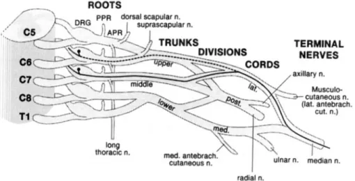
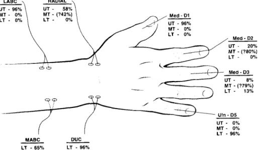
To determine which sensory nerve conduction studies (S-NCS) are helpful in detecting supraclavicular axon loss brachial plexopathies, we selected 53 cases (of 417 reviewed) in whom complicating factors were absent and which, by needle electrode examination findings, involved only a single “truncal” element (upper, middle, or lower) of the brachial plexus. Extensive S-NCS included: median, recording thumb (Med-Dl), index (Med-D2), and middle fingers (Med-D3); ulnar, recording fifth finger (Uln-D5); dorsal ulnar cutaneous, recording dorsum of the hand (DUC); radial, recording base of thumb; and both medial and lateral antebrachial cutaneous (MABC, LABC), recording forearm. Except for the median sensory fibers, the “cord” elements traversed by the sen- sory fibers assessed during the S-NCS listed above are anatomically defined (i.e., the sensory fibers enter the brachial plexus at only one cord). In regard to the median sensory fibers, however, there are two possible pathways through the infraclavicular plexus: (1) the lateral cord and/or (2) the medial cord. Because the lower trunk is only acces- sible via the medial cord, any sensory fibers found to be traversing the lower trunk had to first traverse the medial cord. Similarly, those tra- versing the upper and middle trunks must first be a component of the lateral cord. The frequency that the various S-NCS responses were abnormal (unelicitable, below laboratory normal value, or 6 0 % of the contralateral response) for a given brachial plexus element lesion was as follows: (1) upper trunk (UT): 25 of 26 Med-D1, 25 of 26 LABC, 15 of 26 radial, 5 of 26 Med-D2, 2 of 26 Med-D3; (2) middle trunk (MT): 1 of 1 Med-D3; (3) lower trunk (LT): 25 of 26 Uln-D5, 22 of 23 DUC, 11 of 17 MABC, 3 of 23 Med-D3. With lower trunk brachial plexopathies, both “routine” (Uln-D5) and “uncommon” (DUC; MABC) S-NCS are abnor- mal. With upper trunk brachial plexopathies, in contrast, only the “un- common” S-NCS (Med-D1 ; LABC) are consistently affected. The “rou- tine” median S-NCS recording digit 2 (Med-D2) is far less reliable than the median S-NCS recording digit 1 (Med-D1) in detecting upper trunk axon loss brachial plexopathies. Additionally, the various pathways tra- versed by the fibers contributing to the individual S-NCS responses can be predicted, an important point when the full extent of a brachial plexus lesion is sought. 0 1995 John Wiley & Sons, Inc.
Key words: brachial plexus sensory nerve conduction
MUSCLE 81 NERVE 18:879-889 1995
THE UTILITY
OF
VARIOUS
SENSORY NERVE CONDUCTION
RESPONSES IN ASSESSING
BRACHIAL
PLEXOPATHIES
MARK A. FERRANTE, MD, and ASA J. WILBOURN, M D
From the EMG Laboratory. Neurology Department, Cleveland Clinic Foun- dation, Cleveland, Ohio
This material was presented in part at the San Francisco AAEM meeting on 1 October 1994.
Acknowledgment: We would like to thank Robert W. Shields, Jr., MD, and Erik P.J. Pioro, MD, PhD, for their helpful criticisms and suggestions. Address reprint requests to Asa J. Wilbourn, MD, Cleveland Clinic Foun- dation, EMG Department, Desk S-90,9500 Euclid Avenue, Cleveland, OH
44195
Accepted for publication March 15, 1995.
INTRODUCTION
Dawson4 introduced sensory nerve conduction studies (S-NCS) in 1956. He stimulated the digital nerves of the second and fifth fingers, while re- cording over the median and ulnar nerves at the wrist. In 1958, using these same orthodromic tech- niques, Gilliatt and Searsg showed that both the median and the ulnar sensory nerve action poten- tials (SNAPS) were unelicitable in the presence of diffuse axon loss brachial plexus (BP) lesions, while only the ulnar SNAP was affected by lower trunk CCC 01 48-639W95/080879-11
0 1995 John Wiley & Sons, Inc.
(LT) brachial plexopathies. Thus, they demon- strated that upper extremity S-NCS can be inde- pendently affected by focal brachial plexopathies. Nonetheless, most current textbooks and journal concerned with the elec-
artic.es2.
13,17,2 1,22,27,30trodiagnostic evaluation of the BP discuss upper extremity S-NCS primarily in regard to differenti- ating preganglionic (usually avulsion injuries) from postganglionic lesions, noting that the SNAP amplitudes are affected only by postganglionic axon loss. They also address electrodiagnostic eval- uation of the terminal branch “elements” of the BP. Few sources, however, describe an approach for evaluating the various “internal” BP elements (i.e., trunks and cords), nor do they discuss the internal elements traversed by the sensory fibers studied during the various routine and uncommon S-NCS. Because none of the sensory fibers studied distally traverses all elements of the BP, it is not possible for a single S-NCS to assess the entire BP. Consequently, the individual S-NCS have the po- tential for providing localizing information with focal brachial plexopathies.
While some authors have mentioned only the routine S-NCS (i.e., median, stimulatinghecording the index finger; ulnar, stimulatinglrecording the fifth finger) in regard to BP a s s e ~ s m e n t , ~ ’ ~ others have discussed the importance of perform- i n g u n c o m m o n S-NCS f o r o p t i m a l assess- ment.’~6.’s~24,25~31~32 Still, there have been no series published to validate these claims, nor any attempt to identify the trunk elements evaluated by the routine and uncommon S-NCS. For this reason, we designed this study to determine the BP trunk el- ement traversed by the sensory fibers studied dur- ing the various S-NCS, so that the latter can be logically utilized in the assessment of focal axon loss brachial plexopathies. Because lesions involv- ing the terminal elements (i.e., branches) and pre- ganglionic elements (i.e., roots) are well discussed in other sources, we did not seek to identify them. Moreover, the cord elements traversed by the sen- sory fibers of the S-NCS assessed distally are ana- tomically defined (e.g., the LABC nerve derives from the lateral cord, the radial nerve from the posterior cord, and the ulnar and MABC nerves from the medial cord). The exception to this is the median nerve, which is composed of fibers from both the lateral and medial cords. Still, be- cause the upper and middle trunks can contain median sensory fibers derived only from the later- al cord, and similarly the lower trunk can receive sensory fibers solely from the medial cord, when- ever sensory fibers are shown to traverse a particular
“trunk” element, the “cord” element they traverse is also defined.
METHODS
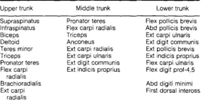
We retrospectively evaluated all electrodiagnostic studies performed at the Cleveland Clinic Foun- dation over the past 11 years that had been coded as a brachial plexopathy ( n = 417). O u r in- clusion criterion was that each BP lesion be con- fined to a single “trunk” element (upper, middle, o r lower), based o n needle electrode exami- nation (NEE), using established muscle domains (Table 1).12,15,16,23,26,33 0 u r exclusion criteria were: (1) evidence of any BP abnormalities not confined to a single trunk element (as noted);
(2)
any other neuromuscular lesion(s) (eg., coexisting carpal tunnel syndrome) in the affected limb; (3) plexopathies studied less than 2 1 days from weak- ness onset; and (4) any S-NCS abnormalities in- volving the contralateral limb; this latter exclusion criterion was applied because the SNAP responses were judged abnormal not only by their absolute values, but also by comparison to the SNAPS of the contralateral unaffected limb. Thus, changes in the contralateral S-NCS could obscure a S-NCS ab- normality of the studied limb.In our study, NEE of a muscle was considered abnormal if it showed evidence of acute and/or chronic motor axon loss (MAL). Acute MAL is re- flected by the presence of fibrillation potentials and a decreased recruitment pattern, whereas chronic MAL is reflected by changes in the exter- nal configuration (e.g., increased duration and sometimes amplitude) and a decreased recruit- ment pattern. Generally, the average duration for a given muscle must be increased by at least 50% before we consider it to be abnormal. Utilizing the NEE of these 417 brachial plexopathies, w e were able to identify 53 lesions confined to a single
Table 1. The muscle domains of the trunk elements Upper trunk Middle trunk Lower trunk
~ Supraspinatus lnfraspinatus Biceps Deltoid Teres minor Triceps Pronator teres Flex carpi radialis Brachioradialis Ext carpi radialis Gnator teres Flex carpi radialis Triceps Anconeus Ext carpi radialis Ext carpi ulnaris Ext digit communis Ext indicis proprius
~ ~~
Flex pollicis brevis Abd pollicis brevis Ext carpi ulnaris Ext digit cornmunis Ext pollicis brevis Ext indicis proprius Flex carpi ulnaris Flex digit prof45 Abd digiti rninirni First dorsal inteross
This fabie is rnoditied from several published rnyotorne charts (Refs 72. 75, 76, 23, 26, 33)
trunk element of the BP: 26 upper trunk (UT); 1 middle trunk (MT); and 26 lower trunk (LT).
T h e majority of BP lesions involving trunk el- ements were rejected from this study because more than a single trunk element was affected: com- bined U T and M T lesions, for example, were far more common than U T lesions alone, as were combined M T and LT lesions compared to LT le- sions in isolation. Also, it is well known that M T lesions rarely occur in isolation, a point again con- firmed by our study (discussed later). Thus, our rigid exclusion criteria necessitated rejection of ap- proximately 87% of the brachial plexopathies re- viewed.
Of the 53 EMG examinations accepted into this study, all had had the following “routine” S-NCS performed: median sensory response, recording digit 2 (Med-D2); ulnar sensory response, record- ing digit 5 (Uln-D5); and radial sensory response, recording dorsum of the hand (radial). Where applicable, additional “uncommon” S-NCS were performed (all antidromically), using published techniques.” These included median sensory re- sponses, recording digit 1 (Med-D1) and digit 3 (Med-D3); dorsal ulnar cutaneous sensory re- sponse, recording dorsum of the hand (DUC); and medial and lateral antebrachial cutaneous sensory responses (MABC, LABC), recording forearm.
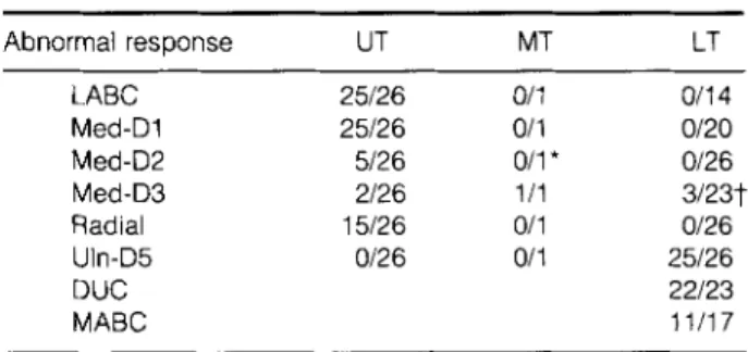
All the S-NCS responses performed in these 53 patients with unilateral BP lesions were evaluated. Peak-to-peak amplitudes were measured from the trough of the first positive component to the peak of the aftercoming negative component. In the event that an initial positivity was not apparent, then the response amplitude was measured from the baseline to the peak of the initial negative com- ponent. In our EMG laboratory we utilize mallea- ble lead grounds (approximately 20 X 2.5 cm) to help reduce shock artifact. In the event that shock artifact is noted, we utilize standard approaches to eliminate it. In all of our 53 cases, shock artifact was not a significant problem. We never found it necessary to resort to such techniques as electronic averaging. Abnormalities were identified when the SNAPS were: (1) unelicitable; (2) lower in ampli- tude than the previously established age-related normal laboratory control values; o r (3) c 5 0 % lower in amplitude than that obtained from the corresponding study on the contralateral limb. It was then determined what effect each BP lesion had on the various S-NCS performed. T h e border- line amplitude decrements (>40%, but <50%) identified in Table 2 were considered as “normals” for all calculations.
RESULTS
Twenty-six U T lesions were identified using the NEE criteria outlined above. Both the LABC re- sponse and the Med-D1 responses were abnormal in 25 of 26 (96%) of these. T h e single “normal” Med-D 1 response was borderline low in amplitude, when compared with the contralateral limb study. T h e radial response was abnormal in 15 of 26 (58%). T h e Med-D2 response was abnormal in only 5 of 26 (19%), and was of borderline low am- plitude in an additional 3 instances. T h e Med-D3 response was abnormal in 2 of 26 (8%). T h e Uln- D5 response was normal in all. These results are listed in Table 2.
Only one M T lesion met the study criteria. T h e Med-D3 response was abnormal with it. The LABC, Med-D 1, Med-D2, radial, and Uln-D5 responses were normal (in this single study), although the Med-2 response was borderline low (47% ampli- tude decrement when compared to the contralat- era1 side). These results are also listed in Table 2.
Twenty-six LT lesions were identified. T h e Med-D3 response was abnormal in 3 of 23 (13%); of the 20 “normal” responses, 2 had borderline amplitude decrements (44%; 47%). Both the Uln- D5 and the DUC responses were abnormal in 96% (Uln-D5: 25 of 26; DUC: 22 of 23); the remaining Uln-D5 response showed a decrement of 43% when compared to the contralateral side, and was thus borderline low in amplitude. T h e MABC re- sponse was abnormal in 11 of 17 (65%) (see Dis- cussion below). T h e following responses were within normal limits: LABC (n = 14), Med-D1 (n
= 20), Med-D2 (n = 26), and radial (n = 26). These results are also listed in Table 2.
DISCUSSION
As pointed out by Stewart,25 knowing the origins of branches arising from the BP, and the muscles
Table 2. The incidence of abnormal S-NCS responses with various BP element lesions.
Abnormal response UT MT LABC 25126 011 Med-D1 25/26 011 Med-D2 5/26 011 * Med-D3 2/26 111 Radial 15/26 011 Uln-D5 0126 01 1 DUC MABC LT 011 4 0120 0126 3/23? 0126 25/26 22/23 11/17
*The “normal” response revealed a 46% amplitude decrement in comparison to the other side.
jTwo of the “normal” responses revealed borderline amplitude decrements (44%, 47%).
and cutaneous areas they supply, is important in the accurate localization of brachial plexopathies. Although S-NCS have been known to be useful in the electrodiagnostic evaluation of brachial plex- opathies for over 35 years,g the potential for their anatomy to be applied electrodiagnostically has been underutilized. Axon loss lesions at the plexus level separate the sensory cell bodies in the dorsal root ganglia (DRG) from their peripheral projec- tions (axons), causing the latter to undergo Walle- rian degeneration. When these degenerated nerve fibers are a component of a sensory nerve assessed during S-NCS, they do not contribute to the SNAP and, consequently, its amplitude is decreased. With rather severe lesions the S-NCS responses become unelicitable. Because the sensory fibers assessed by a single S-NCS do not traverse all the BP elements, there is no single S-NCS capable of assessing all the BP elements simultaneously. Consequently, know- ing the pathway through the plexus traversed by the sensory fibers assessed during S-NCS can he very helpful in BP evaluation.
Each of the 53 cases included in this study was selected because it had NEE abnormalities re- stricted to muscles within the domain of just a sin- gle trunk element, as determined by various stan- dard myotome charts. 12,15,16.23,26,33 T h e N E E
abnormalities included fibrillation potentials, fre- quently accompanied by a neurogenic motor unit potential (MUP) firing pattern (decreased recruit- ment), and sometimes by chronic neurogenic MUP changes. T h e degree of acute versus chronic MAL is a reflection of the temporal relationship between the onset of symptoms and the time the NEE was performed. As stated previously, all studies were performed at least 3 weeks after the onset of weak- ness. Given that the S-NCS responses are much more susceptible to pathologic insult than are the M-NCS responses, the acuteness or chronicity of the NEE findings does not adversely influence our interpretation.
Table 1 shows the muscle domains for the 3 trunk elements of the BP. It was derived from pre- viously published studies’2’15’16,23,26,33 dealing with the muscle domains of various root (i.e., an- terior primary rami, APR) elements. Except for the relatively few peripheral nerves arising from the APR level of the BP (e.g., dorsal scapular nerve, long thoracic nerve), the trunk elements of the BP are direct continuations of the APR (i.e., the U T is formed by the fusion of the C5 and C6 APR, the M T is a direct continuation of the C7 APR, and the LT is formed by the fusion of the C8 and T 1 APR).I4 Thus, the muscle domain of a
given trunk element is equal to the muscle do- main(s) of its contributing APR, minus the muscle domain(s) of the peripheral nerves (if any) given off at the APR level of the BP. The overlap in our table, like the overlap in the studies from which it was derived, reflects the fact that essentially all of the muscles sampled on NEE receive multisegmen- tal innervation. Thus, in order to accurately local- ize axon loss BP lesions, one must be familiar with the muscle domains of all the BP elements. For example, if we noted NEE abnormalities in the su- praspinatus, infraspinatus, deltoid, biceps, bra- chioradialis, and pronator teres muscles, the lesion was considered an UT brachial plexopathy. All of the above muscles receive motor axons from the C5 and C6 segments of the spinal cord, except for the pronator teres, which receives motor axons from the C6 and C7 segments. Thus, motor axons innervating the pronator teres traverse both the U T and the MT. Given that no abnormalities were noted in any other muscles of the M T muscle do- main, we considered it unlikely that the lesion was affecting both the U T and the M T ; rather, we assumed it involved the U T in isolation and the pronator teres contained fibrillation potentials be- cause of its C6/UT innervation. A second, more complex example of this reasoning process, is that of the single M T lesion identified in this study. Note in Table 1 that 4 of the muscles listed in the M T muscle domain are also listed in the U T mus- cle domain, and that 3 of them also appear in the LT muscle domain. Because it lies between 2 other trunk elements, its muscles are for the most part “shared.” It becomes important, therefore, to sam- ple the “unshared” muscles of both the upper and lower trunks. If they are all spared, and only if they are all spared, then the possibility that the lesion is a mixed trunk element lesion is quite re- mote, since it is very unlikely that involvement of a second trunk element would affect only those mo- tor nerve fascicles innervating muscles found in both domains, while sparing the “unshared” mus- cles. Our M T case went to surgery, based in part on our electrodiagnostic examination, and was found to have a fibrotic process of unknown etiol- ogy involving solely the MT. The overlap seen in the M T muscle domain is analogous to that seen in the C7 APR muscle domain (as expected given that it is a direct continuation of that root), and we are unaware of any electromyographers who consider
it impossible to make a diagnosis of a C7 radicu- lopathy. Thus, the rarity of an isolated M T lesion is not due to the complexity involved in making the electrodiagnosis. Although the muscle domains of
the BP elements overlap, the “shared” muscles are important in evaluating the full extent of a brachial plexopathy, so we elected to utilize them in our search for focal lesions. Moreover, we were con- cerned that excluding such lesions would result in a selection bias toward more partial (i.e., less se- vere) BP element lesions. Less severe lesions would be more likely to spare the sensory fibers studied by the various S-NCS and could adversely affect our results.
We are well aware of the limitations of this ap- proach. First, variations in BP anatomy (both ver- tical and horizontal variations) could conceivably have an affect on both the NEE and the NCS find- ingS.5,1O,28,34.35 p erhaps the most discussed BP anomaly is that of pre- and post-fixation.29 It is interesting to note, however, that with these verti- cal anomalies, while the root contribution of the trunk elements changes, the plexus arrangement itself remains the same. Thus, although the sen- sory fibers derive from an adjacent DRG (either the one above o r the one below the “typical” DRG), the pattern of NCS and NEE abnormalities would localize to the same BP element. Regarding hori- zontal variations, Leffert14 has reported that the trunk elements are seldom anomalous, the M T be- ing a direct extension of the C7 APR in 10096, and the U T and LT being of “classical” formation in >90% and >95%, respectively.
A second limitation of this study is that we often were unable to verify that the BP trunk element identified electrodiagnostically was truly the patho- logical site of involvement. Neuroimaging studies (which were not performed on all patients) usually were not helpful because they are not sensitive enough to permit lesion identification confined to a single trunk element. Similarly, operative verifi- cation that only one BP element was involved was not possible because only a minority of our patients underwent surgical exploration (e.g., the M T case). Yet electromyographers are called upon to assess all BP lesions, regardless of whether or not they are surgically explored. Moreover, even if all patients underwent surgical confirmation, electrodi- agnostic evaluation would still be required preop- eratively, and thus the dilemma would remain. We, like other authors before us, did the next best thing. We correlated all of our electrodiagnostic impressions with the clinical examinations. In ad- dition to credible histories of a focal BP lesion, all 5 3 cases had clinical examination features consis- tent with involvement of the BP element ultimately diagnosed by NEE. T h e NEE either confirmed the clinical impression or further refined it.
While our brachial plexopathy series represents a biased population (i.e., focal brachial plexopa- thies), their etiologies were varied: trauma (18), true neurogenic thoracic outlet syndrome ( l o ) , post median sternotomy (open heart surgery) (7), neoplastic (4), neuralgic amyotrophy ( 3 ) , post irra- diation treatment ( l ) , iatrogenic (l), neurofibro- matosis type I (l), and unknown (8). Of note is that in the 3 patients with neuralgic amyotrophy, both the clinical and NEE features were suggestive of an U T BP lesion and not, as is more often the case, one or more proximal m o n o n e ~ r o p a t h i e s . ~
T h e individual S-NCS and the likely course of their sensory fibers through the BP will next be discussed.
The LABC Response. The lateral antebrachial cu- taneous nerve is the terminal portion of the mus- culocutaneous nerve, derived from the LC of the BP. Consequently, by anatomical definition, the “cord” element traversed by the sensory fibers as- sessed by the LABC S-NCS is the lateral cord. Thus only LC lesions, but not PC or MC lesions, have the potential to affect the LABC S-NCS at the “cord” level of the BP. With regard to the trunk elements that the LABC fibers traverse, they could traverse the upper trunk, the middle trunk, o r both. Since the LABC response was abnormal in 25 of 26 U T lesions, our results suggest that they traverse predominantly the UT. Our study did not adequately assess the MT, since only one M T le- sion was identified. However, Inouye and Buch- thal” recorded spinal nerve potentials evoked by stimulation of the sensory fibers of the musculocu- taneous nerve and showed that the maximum am- plitude occurred at the C6 root, while Yoss and coworkers35 have shown that C6, but not C5, ra- diculopathies cause sensory symptoms in the later- al forearm (i.e., in the sensory distribution of the LABC nerve). These studies support our finding that the predominant course taken through the BP for those sensory fibers assessed by the LABC S-NCS is the LC and the UT. They also suggest that the sensory axons assessed by the LABC SNAP have their cell bodies of origin in the C6 DRG cells. Importantly, the LT element of the BP is not assessed by the LABC sensory response (nor are the MC or PC). Figure 1 illustrates the sug- gested pathway.
The Med-Dl Response. T h e median nerve is com- posed of fibers derived from both the LC and the MC. Because the Med-D1 response was abnormal in 25 of 26 U T lesions, 0 of 1 M T lesion, and 0 of
ROOTS p p ~ dorsal scapular n. TERMINAL NERVES med. antebrach. cutaneous n. radial n.
FIGURE 1. Proposed brachial plexus pathway for the sensory fibers assessed by the LABC SNAP.
20 LT lesions, our study suggests that the Med-D1 SNAP is elicited from fibers that traverse the U T (and LC). Whether or not some of the fibers it assesses sometimes traverse the M T could not be determined by this study because only a single M T lesion was identified. Of importance is that the LT, MC, and PC elements of the BP are not assessed by the Med-D1 sensory response. Figure 2 illustrates the suggested pathway.
The Med-D2 Response. T h e Med-D2 SNAP was abnormal in 5 of 26 U T lesions, although 3 of 21 “normal” responses were borderline low in ampli- tude when compared to the contralateral side (see Table 2). T h e Med-D2 SNAP was abnormal with 0 of 1 M T lesion, but this response was borderline low in amplitude (47%) compared to that found in the contralateral limb (see Table 2). T h e Med-D2 SNAP was abnormal with 0 of 26 L T lesions. Even
though only one M T lesion was available for eval- uation (borderline low in amplitude), the absolute lack of involvement of the Med-D2 SNAP with LT lesions coupled with the rather minimal involve- ment (32% at most, if borderline low amplitudes are included as abnormal) with U T lesions sug- gests, by default, that the M T is the trunk element most often traversed by the sensory fibers supply- ing the index finger. However, due to the limited number of M T lesions in our study, no definite conclusions can be drawn. Nonetheless, it is perti- nent to note that while we were collecting the 53 isolated trunk element lesions included in this study, we rejected dozens of plexopathies in which the Med-D2 response was abnormal because, on NEE, abnormalities were present outside of the predefined M T muscle domain (i.e., they were UTiMT or MTiLT lesions). Thus, the Med-D2 re- sponse assesses the UT in a minority of patients, ROOTS
_-
- -.. , p p ~ dorsal scapular n. /-k,?
ERG ., suprascapular n. I,’ c5 /’ ,...
I 2.--
I
TERMINAL - >. .
L1
Ulnarn. median n. meo. anreoracn. cutaneous 0 . . . . -.--
.- . . . radial n.FIGURE 2. Proposed brachial plexus pathway for the sensory fibers assessed by the Med-D1 SNAP.
presumably the M T in most patients, and the LC in all patients. Importantly, the LT (along with the MC and the PC) element is not assessed by the Med-D2 response. Figure 3 illustrates the sug- gested pathway.
The Med-DB Response. T h e Med-D3 SNAP was abnormal in 2 of 26 U T lesions, 1 of 1 M T lesion, and 3 of 23 LT lesions (2 of the 20 “normal” with LT lesions were borderline low in amplitude, 44% and 47%, compared to the other side) (see Table 2). These findings suggest that the sensory fibers supplying the middle finger can traverse the UT, M T , and/or L T elements. Because o u r study showed that the Med-D3 response was seldom af- fected with isolated U T lesions, it is probable that the sensory axons subserving this response derive primarily from the C7 DRG and therefore traverse the MT. However, because only one isolated M T lesion was included in this study, no definite con- clusions are possible. Nonetheless, analogous to the circumstances surrounding the Med-D2 re- sponse, we found that the Med-D3 response was typically abnormal with combined U T and M T brachial plexopathies, as well as with combined M T and L T lesions. This again suggested that the M T is the predominant trunk element traversed by the sensory fibers contributing to the Med-D3 SNAP. T h e major difference between the Med-D2 and the Med-D3 responses was that the latter was abnormal with 13% of the LT lesions, revealing, contrary to past beliefs, that the median sensory axons contributing to the Med-D3 SNAP some- times pass through the MC and the LT elements of the BP on their way to their DRG cell bodies of ori- gin. The suggested pathways are shown in Figure
4.
The Radial Responses. T h e radial sensory re- sponse was abnormal with 15 of 26 (58%) lesions involving the UT, 0 of 1 affecting the M T , and 0 of 26 involving the LT. As with the Med-D2 and Med-D3 responses, accurately determining the M T contribution was not possible, because only 1 M T lesion was identified. However, the fact that the radial SNAP was abnormal in only 58% of U T lesions suggests that this is not the only trunk ele- ment these fibers traverse. Moreover, the fact that the radial SNAP was normal in all 26 LT lesions indicates that the L T is not the additional trunk element traversed. By default, these results suggest that the M T serves as an important conduit for radial sensory fibers approximately 42% of the time. Supporting this concept is that the radial SNAP frequently was abnormal both with com- bined UT/MT lesions and with combined MT/LT lesions, two categories of BP lesions not included in this study. This concept is also supported by the work of Inouye and Buchthal,” who showed that the maximum amplitude response with radial nerve stimulation occurred at the C6 and C7 roots, suggesting that the U T and M T function as path- ways for these fibers. Thus, the radial sensory fi- bers appear to traverse both the U T and the M T (the particular pathway varying from patient to pa- tient) as well as the PC. Importantly, the radial sensory fibers do not traverse the LT, MC, or LC. Figure 5 depicts the suggested pathways.
The Uln-DS and DUC Responses. By anatomic def- inition, the sensory fibers contributing to the Uln- D5 and the DUC SNAPS must traverse the MC and the LT BP elements. Thus, it is not surprising that the Uln-D5 SNAP was abnormal in 25 of 26 LT
/- - -^.I ROOTS
TERMINAL
med. antebrach. cutaneous n.
radial n.
FIGURE 3. Proposed brachial plexus pathway for the sensory fibers assessed by the Med-DP SNAP.
med. antebrach.
\..’
I
- \ IUlnal n. median n. cutaneous n.
radial n.
FIGURE 4. Proposed brachial plexus pathway for the sensory fibers assessed by the Med-D3 SNAP. lesions, with the only “normal” response showing a
borderline amplitude decrement compared to the other side. T h e DUC SNAP was abnormal in 22 of 23 LT lesions. Thus, our results confirm the un- disputed fact that the Uln-D5 and DUC SNAPs evaluate the MC and LT elements of the BP; they do not assess the UT, M T , LC, or PC.
We did not perform a DUC S-NCS on any of our U T patients, because the sensory fibers sub- serving this response are known not to traverse the UT, and the studies, as is, were already quite time- consuming. Moreover, as these data show, the DUC S-NCS response was always abnormal when- ever the Uln-D5 S-NCS response was abnormal; and we did perform an Uln-D5 S-NCS in all 53 of these patients (and thus in all 26 of the U T lesions). As suspected, it was never involved.
The MABC Response. T h e medial antebrachial cu- taneous nerve originates from the MC, which is
ROOTS
continuous with the LT. By anatomical definition, the MABC SNAP should assess fibers that traverse the LT element of the BP. Our study confirmed this, showing abnormal MABC SNAPs in 11 of 17 LT lesions. However, a pertinent question arises: “Why were only two thirds of the MABC sensory responses affected by the LT lesions if this is the only trunk element traversed by these sensory fi- bers?” First, it is important to note that all the LT plexopathies in which the normal MABC response occurred had the same etiology: postmedian ster- notomy. These particular LT plexopathies (i.e., those associated with median sternotomy) differ from most other LT lesions in that they consis- tently affect the ulnar motor and sensory fibers disproportionately more than they affect the C8/ T 1 median motor fibers and the MABC fibers. We beli