PERFORMANCE BASED STANDARDS SCHEME THE STANDARDS AND VEHICLE
ASSESSMENT RULES
as at 10 November 2008 (incorporating all amendments consented to by the ATC
up to that date)
Prepared by National Transport Commission
Performance-Based Standards Scheme
– the Standards and Vehicle
Assessment Rules
as at 10 November 2008 (incorporating
all amendments consented to by the ATC
up to the date)
National Transport Commission
PBS Scheme – The Standards and Vehicle Assessment Rules
These Rules were made by the National Transport Commission on 30 July 2007, and were approved by the Australian Transport Council on 3 October 2007. This version of the Rules includes amendments that were consented to by the Australian Transport Council on 7 November 2008.
CONTENTS
PART 1 – INTRODUCTORY MATTERS ...1
1. Purpose of these Rules ...1
2. The Standards to be met ...1
3. Exempt prescriptive provisions ...1
PART 2 – RULES FOR ASSESSORS...2
Division 1 – General duty and overview ...2
4. General duty ...2
5. Overview of the assessment process ...2
6. Non-complying vehicle not to be certified ...3
Division 2 – Modelling and testing procedures ...3
7. [Reserved] ...3
8. Assessment procedures for safety standards...3
9. Required vehicle physical characteristics must be recorded ...3
10. Specific requirements concerning the recording of vehicle physical characteristics ...3
11. Parameter sensitivity testing ...4
12. General requirements ...4
13. Sensitivity testing of vehicle design features ...5
14. Sensitivity testing of vehicle operating factors ...5
15. How risk sensitive parameters are to be ranked...6
17. Certifying compliance with individual standards ...7
18. Certifying a vehicle design/vehicle – primary assessors...7
18ACertifying an alternatively complying vehicle design/vehicle – primary assessors...7
19. General requirements concerning completion of certificates ...8
20. Retention of documents ...8
PART 3 – AMENDMENT OF THESE RULES ...8
21. Amendment of these Rules ...8
PART 4 – INTERPRETATIVE MATTERS AND REFERENCES ...9
22. Definitions of general terms ...9
23. Reference provisions ...10 24. Technical terms ...10 25. Diagrams ...11 26. Notes ...11 27. Examples ...11 28. References to documents ...11
APPENDIX A: THE INFRASTRUCTURE STANDARDS... 13
APPENDIX B: [RESERVED] ... 19
APPENDIX C: THE SAFETY STANDARDS... 21
APPENDIX D: [RESERVED] ... 71
APPENDIX E: ASSESSING SAFETY STANDARDS BY NUMERICAL MODELLING ... 73
APPENDIX F: ASSESSING SAFETY STANDARDS BY PRACTICAL TESTING ... 101
APPENDIX H – RISK SENSITIVE PARAMETERS RELATED TO VEHICLE DESIGN FEATURES ... 149
APPENDIX J – INFORMATION AND RECOMMENDATIONS
CONCERNING VEHICLE OPERATING CONDITIONS...161
APPENDIX K - CERTIFICATE THAT A DESIGN/VEHICLE MEETS ALL THE PERFORMANCE BASED STANDARDS ...163
APPENDIX L - CERTIFICATE THAT A DESIGN/VEHICLE MEETS ONE OR MORE SPECIFIC PERFORMANCE BASED STANDARDS...167
APPENDIX M - CERTIFICATE FOR A DESIGN/VEHICLE THAT DOES NOT MEET ALL THE PERFORMANCE BASED STANDARDS...167
LIST OF TABLES
Table 1. Ranking of risk sensitive parameters ... 6Table 2. Maximum gross mass permitted with one or two driving axles ... 15
Table 3. Safety Standards... 21
Table 4. Startability performance levels... 22
Table 5. Gradeability - Part (a) Maintain Motion performance levels... 25
Table 6. Gradeability - Part (b) Maintain Speed performance levels ... 26
Table 7. Acceleration capability performance levels ... 27
Table 8. Network classification by vehicle length ... 29
Table 9. Tracking ability performance levels ... 32
Table 10. Low speed swept path performance levels ... 37
Table 11. Frontal swing performance levels ... 41
Table 12. Maximum difference of frontal swing path performance levels ... 44
Table 13. Difference of maximum frontal swing out for performance levels ... 45
Table 14. Tail swing performance levels ... 47
Table 15. Steer tyre friction demand performance levels ... 50
Table 16. Static rollover threshold performance levels ... 53
Table 17. Rearward amplification performance levels ... 57
Table 18. High speed transient offtracking performance levels ... 63
Table 19. Yaw damping performance levels ... 66
Table 20. Deceleration levels for vehicles participating in the Scheme... 68
Table 21. Numerical Modelling - Safety standards references... 73
Table 22. General application information ... 97
Table 23. Vehicle dimensions... 97
Table 24. Mass properties... 97
Table 25. Suspensions... 98
Table 26. Tyres... 98
Table 27. Chassis properties (flexible) ... 98
Table 28. Powertrain... 98
Table 29. Standards assessed with models described in Tables 30 to 34... 98
Table 30. Suspension vertical spring element... 99
Table 31. Suspension spring elements (roll) ... 99
Table 32. Suspension damping elements (roll) ... 99
Table 33. Suspension other features... 99
Table 35. Numerical modelling results ...100
Table 36. Practical testing - Safety standards references ...101
Table 37. Tracking ability instrumentation requirements ...106
Table 38. Low speed swept path instrumentation requirements ...108
Table 39. Frontal swing instrumentation requirements ...109
Table 40. Tail swing instrumentation requirements ...111
Table 41. Steer tyre friction demand instrumentation requirements ...113
Table 42. General application information ...133
Table 43. Driver details...133
Table 44. Prime mover specification...134
Table 45. Transducer location ...134
Table 46. Vehicle unit details ...135
Table 47. Vehicle unit dimension details ...135
Table 48. Axle group mass details ...136
Table 49. Tyres ...136
Table 50. Test conditions ...137
Table 51. Weather conditions ...137
Table 52. Testing personnel...137
Table 53. Vehicle safety check ...138
Table 54. Test results ...138
Table 55. Comments ...140
LIST OF FIGURES
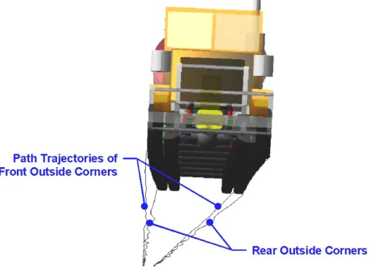
Figure 1. Perspective view illustration of front and rear outside-corner path trajectories and swept width in the tracking ability on a straight path test...31Figure 2. Underside perspective view illustration showing typical characteristics of the path trajectories and offsets due to cross slope. ...31
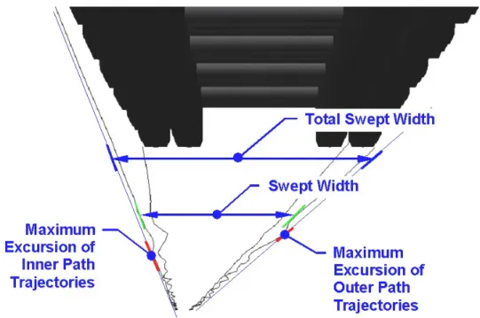
Figure 3. Close-up underside perspective view illustration showing both the swept width envelope and Total Swept Width from the 4 path trajectories defined in Figures 1 and 2...32
Figure 4. Perspective view illustration of vehicle partway through the Performance Based Standards low-speed turn showing path trajectories. ...36
Figure 5. Plan view illustration of path trajectories that define the vehicle’s swept path in the Performance Based Standards low-speed turn. ...36
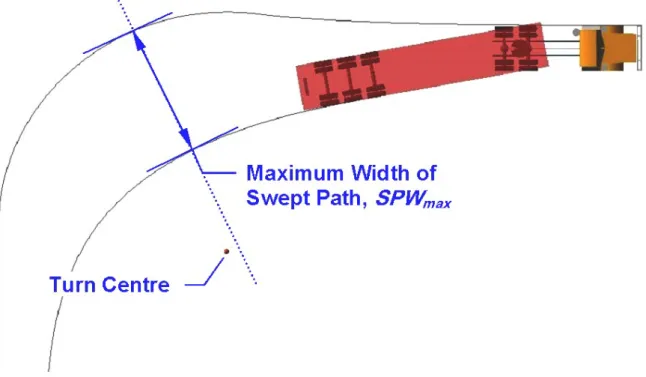
Figure 6. Plan view illustration of Maximum Width of Swept Path, SPWmax. Note that the line perpendicular to both path trajectories (shown dotted in the illustration) does not necessarily pass through the turn centre...37
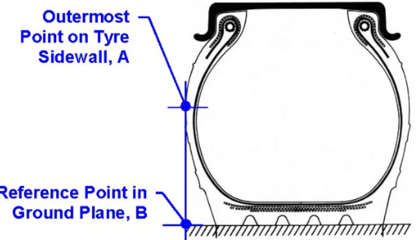
Figure 7. Illustration of outside wheel reference point. ...38
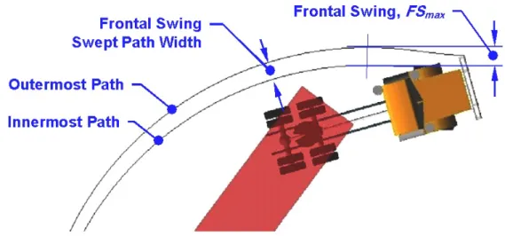
Figure 8. Illustration of path trajectories in the Performance Based Standards low-speed turn of Part A of the frontal swing performance measure. For this measure the innermost path is the path followed by the outside front wheel...40
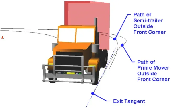
Figure 9. Perspective view illustration of path trajectories partway through the Performance Based Standards low-speed turn for Parts B and
C of frontal swing MoD and DoM performance measures. ... 42
Figure 10. Perspective view illustration of Parts B and C of the frontal swing
MoD and DoM performance measures looking along the exit
tangent during the final stages of the low-speed turn. ... 42
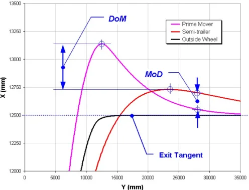
Figure 11. Further detail on the Parts B and C frontal swing DoM and MoD
performance measures. Note that the vertical (X) axis scale is
exaggerated. ... 43
Figure 12. A contrasting example to the one shown in Figure 11 of the Parts B
and C frontal swing DoM and MoD performance measures. Note
that the vertical (X) axis scale is exaggerated... 43
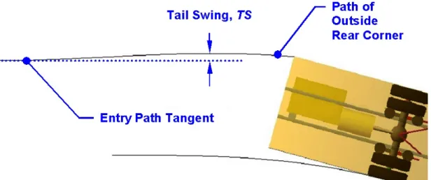
Figure 13. Illustration of tail swing performance measure at commencement
of the Performance Based Standards low-speed turn. ... 47
Figure 14. SAE Tyre Axis System (Society of Automotive Engineers, 1976) ... 49
Figure 15. Typical axle lift-off sequence and rollover threshold for a prime
mover and semi-trailer combination. ... 52
Figure 16. Side and plan view illustration of 2 roll-coupled trailers showing
sprung masses, sprung mass centre of gravity heights, and lateral accelerations, AY. ... 54
Figure 17. Illustration of rearmost roll-coupled units (rrcu) in 3 example
vehicles; a prime mover and semi-trailer combination, an A-triple,
an AAB-quad and a Double B-Triple. ... 58
Figure 18. Perspective view illustration of final stages of the single lane
change manoeuvre showing overshoot dimension in the ground
plane of the rear axle centre for high-speed transient offtracking... 62
Figure 19. Illustration of high-speed transient offtracking overshoot and
undershoot scenarios from Society of Automotive Engineers
(1993a)... 62 Figure 20. Determination of amplitudes for damping ratio calculation. ... 65 Figure 21. Illustration of roll steer effect on a beam axle (from Fancher et al,
1986). ... 83
Figure 22. Side force characteristics of an 11R22.5 size truck tyre showing
the influence of tyre vertical load. ... 84
Figure 23. Aligning moment characteristics of an 11R22.5 size truck tyre
showing the influence of tyre vertical load. ... 85 Figure 24. Exact form of the pulse steer input given by equation E4a. ... 90 Figure 25. Idealised brake forces acting on a semi-trailer. ... 92
PART 1 – INTRODUCTORY MATTERS 1. Purpose of these Rules
The purpose of these Rules is to specify –
(a) the Performance Based Standards that must be met for a vehicle to be eligible to participate in the Performance Based Standards Scheme; and (b) the methods of assessment and the procedures for assessment that must be
used by assessors to determine if those Standards are met in any particular case.
2. The Standards to be met
(1) To be eligible to participate in the Scheme, a vehicle must meet – (a) all of the infrastructure standards set out in Appendix A; and (b) all of the safety standards set out in Appendix C.
(2) In general, a vehicle meets those standards for the purposes of the Scheme if either –
(a) the design of the vehicle is assessed in accordance with these Rules as having a high probability of meeting all of those standards, and it is established that the vehicle was built according to that design; or
(b) the vehicle is assessed in accordance with these Rules as meeting all of those standards.
3. Exempt prescriptive provisions
(1) If a vehicle is eligible to participate in the Scheme, it may be exempted from – (a) any of the following provisions of the Australian Vehicle Standards that are
incompatible with its design – (i) clause 66 (Width);
(ii) clause 67 (Length of single motor vehicles); (iii) clause 68 (Length of single trailers);
(iv) clause 69 (Length of combinations);
(v) clause 70 (except subclause (3)(a))(Rear overhang); (vi) clause 71 (Trailer drawbar length);
(vii) clause 72 (Height);
(viii) clauses 169 (b) and (c) (Attachment of couplings and drawbar eyes on long road trains);
(b) any of the following provisions of the Australian Design Rules that are incompatible with its design –
(i) Rule 43, clause 6.1 (Length);
(ii) Rule 43, clause 6.2 (Rear overhang)(other than clause 6.2.1); (iii) Rule 43, clause 6.3 (Height);
(iv) Rule 43, clause 6.5 (Width);
(v) Rule 43, clause 9.4 (Retractable axles); (vi) Rule 43, clause 9.5 (Retractable axles); (vii) Rule 62, clause 5.3 (Tow coupling overhang); (viii) Rule 63, clause 63.5.1 (Tow coupling location).
(2) Despite subrule (1)(b)(ii), if a trailer to which clause 6.2.1 of Rule 43 applies is eligible to participate in the Scheme and has a rear overhang of more than 3.7 metres, it may be exempted from that clause if it otherwise complies with that clause.
PART 2 – RULES FOR ASSESSORS
Division 1 – General duty and overview
4. General duty
An assessor assessing a vehicle design or a vehicle for the purposes of the Scheme must comply with all of the requirements set out in these Rules.
5. Overview of the assessment process
(1) To conduct an assessment of a vehicle design or a vehicle for the purposes of the Scheme, the assessor must assess the design or vehicle against the requirements of the standards by means of numerical modelling or testing conducted in accordance with Division 2.
(2) If the assessor is of the opinion that the design or vehicle will, or does, meet the standard or standards in respect of which the modelling or testing was conducted to the extent required by these Rules, he or she must –
(a) identify and record the vehicle physical characteristics of the design or vehicle in accordance with Division 3; and
(b) conduct, if thought necessary, one or more risk sensitivity analyses of the design or vehicle in accordance with Division 4; and
(c) consider whether to recommend any national operating conditions in respect of the design or vehicle in accordance with Division 5; and
(d) determine from which of the prescriptive requirements listed in rule 3 the design or vehicle will need exemption; and
(e) issue any certificate required by Division 6.
6. Non-complying vehicle not to be certified
If the assessor determines that a vehicle design or vehicle will not, or does not, meet one or more of the standards to the extent required by these Rules, and is not likely to be eligible for approval under rule 33A or 33B of the Performance Based Standards Scheme: Review Panel Business Rules, he or she must not issue a certificate in relation to the vehicle.
Division 2 – Modelling and testing procedures
7. [Reserved]
8. Assessment procedures for safety standards
(1) To assess a vehicle design or a vehicle against a safety standard specified in Appendix C, the assessor must carry out modelling or testing in accordance with any requirements for Test Specification in Appendix C, unless another Appendix expressly provides for another specification, and –
(a) if the assessment is undertaken by numerical modelling, the procedures in Appendix E must also be followed;
(b) if the assessment is undertaken by testing, the procedures in Appendix F must also be followed.
(2) If a vehicle is to be field tested and the assessor is responsible for organising that testing, he or she must ensure that a site manager is on site before any testing starts, and that the site manager remains on site during the whole of the field testing programme. The assessor may also be the site manager.
Division 3 – Vehicle physical characteristics
9. Required vehicle physical characteristics must be recorded
(1) As part of the assessment process, the assessor must complete the Vehicle Certification Information (Appendix G) for the vehicle design.
(2) The assessor must ensure that the Vehicle Certification Information sets out a complete description of the vehicle physical characteristics that a vehicle built to the design must have to enable the vehicle to meet the standards.
(3) The assessor may refer, in an entry in the Vehicle Certification Information for a design, to drawings or other information, provided the link is clearly identifiable, and the drawings or other information are attached to the Information.
10. Specific requirements concerning the recording of vehicle physical characteristics
(1) The assessor must comply with the requirements of this rule in completing the Vehicle Certification Information (Appendix G).
(2) For each trailer, semi-trailer or dolly proposed in a design, the assessor must identify the vehicle physical characteristics for each separate vehicle unit, and must also identify the position of the vehicle unit in the proposed combination.
(3) The assessor must specify all dimensions as a maximum, a minimum, or as a maximum and a minimum (i.e. a range).
(4) The assessor must specify the vehicle physical characteristics in a way that allows the characteristics to be checked using one or more of the following methods – (a) physically checking the vehicle by straightforward measurements taken by a
certifier;
(b) checking by a simple visual inspection of components by a certifier (for instance, this could involve confirming the make, model and serial number of specific components such as the chassis, engine or transmission, or of entire suspension assemblies or individual suspension components (shock absorbers, airbags, springs, and the like), tyres, and other features or components that are considered to be risk sensitive);
(c) checking by a certifier by sighting written documents from service providers (these could include other assessors not involved with the specific assessment), manufacturers or component suppliers/testers.
(5) If vehicle physical characteristics cannot be specified using one or more of the methods in subrule (4), the assessor must specify a reasonable way for a certifier to check the characteristic.
Division 4 –Sensitivity testing
11. Parameter sensitivity testing
(1) This Division applies if it appears to the assessor that, in respect of either a design feature or an operating factor, there is a significant risk that a vehicle built to the design being assessed by the assessor may not perform as designed as a result of off-baseline variations in the characteristics of a relevant critical component, sub-assembly or load.
(2) The assessor must undertake a parameter sensitivity analysis in relation to the design’s compliance with the standard or standards in respect of which the risk arises with a view to determining whether or not it may be necessary to take steps to control the risk (such as by the imposition of one or more operating conditions).
12. General requirements
(1) If a parameter sensitivity analysis is undertaken, the assessor must list risk sensitive parameters and the off-baseline variation used (%) in the same form as is shown in Appendix H or Appendix I, as the case may be.
(2) If there is more than one trailer, semi-trailer or dolly proposed in a design, the assessor must identify the relevant risk sensitive parameters for each separate vehicle unit, and must also take into account the position of each vehicle unit in the proposed combination.
13. Sensitivity testing of vehicle design features
(1) This rule applies if an assessment of risk sensitive parameters that relate to vehicle design features is undertaken.
(2) The risk sensitive parameters that should be considered in an initial sensitivity analysis for particular safety standards are set out in Appendix H. The parameters listed are not intended to be all-inclusive, and there may be other parameters that the assessor chooses to consider in response to any unique features of a design. By the same token, nothing in this Division requires the assessor to conduct a sensitivity analysis for a parameter in respect of a particular application if the assessor considers that the parameter is not significant (in a practical sense) to that application.
(3) The baseline figure the assessor must use in conducting a sensitivity analysis in respect of a standard, or an aspect of a standard, is –
(a) in the case of numerical modelling, the performance achieved in respect of that standard, or aspect, as recorded in Table 36; or
(b) in the case of physical testing, the result or reference in respect of that standard, or aspect, as recorded in Table 55.
(4) A sensitivity analysis must consider off-baseline variations in parameter values caused by –
(a) the following known variations –
(i) expected variations due to manufacturing tolerances;
(ii) expected variations in the performance characteristics of like components sourced from the same or different suppliers;
(iii) expected in-service variations due to normal wear and tear; and (b) other known variations.
(5) If variations in parameter values are not known or cannot be reasonably estimated, they are to be taken to be ±20% of the baseline values.
(6) The assessor must recalculate the performance of the vehicle design with respect to the standard using the maximum value of the off-baseline variation range, and then must repeat the calculation using the minimum value of the off-baseline variation range.
(7) The assessor must identify a parameter as a risk sensitive parameter if he or she determines that an off-baseline variation produces a change in the value of the standard outcome of not less than 2.0%.
14. Sensitivity testing of vehicle operating factors
(1) This rule applies if an assessment of risk sensitive parameters that relate to vehicle operating factors is undertaken.
(2) The risk sensitive parameters that should be considered in an initial sensitivity analysis for particular safety standards are set out Appendix I. The parameters
listed are not intended to be all-inclusive, and there may be other parameters that the assessor chooses to consider.
(3) The assessment must be carried out in a manner similar to that required for vehicle design features in rule 13.
(4) The sensitivity analysis must consider the likely largest in-service variations, and where variations are unknown, then the variation is to be taken to be ±20% of the baseline values.
15. How risk sensitive parameters are to be ranked
(1) Risk sensitive parameters must be ranked as specified in Table 1.
Table 1. Ranking of risk sensitive parameters
Ranking Percentage change in numerical value of safety standard
1 20.0% or more
2 2.0% or more but less than 20.0%
(2) The initial rankings shown in Appendix H and in Appendix I are indicative only. Actual rankings can vary from one vehicle design to another and will depend on specific design features, operating conditions and the commodity transported.
Division 5 – Recommendations on conditions
16. Assessor must consider whether national operating conditions desirable
(1) After conducting any testing required by Division 4, the assessor must – (a) complete items 1 – 3 of Appendix J; and
(b) in the light of that information and the results of the testing, consider whether to recommend that the vehicle, or a vehicle built to the design, assessed by him or her should be made subject to one or more operating conditions once it begins to operate; and
(c) if he or she considers that one or more operating conditions should be imposed, list that condition, or those conditions, in item 5 of Appendix J. (2) In considering whether to recommend the imposition of operating conditions, the
assessor must have regard to the Performance Based Standards: Guidelines for Determining National Operating Conditions, as approved by the Australian Transport Council from time to time.
Division 6 – Certificates of compliance
17. Certifying compliance with individual standards
(1) If an assessor has assessed a vehicle design in relation to a standard and is of the opinion that a vehicle built to that design will meet the standard, he or she must issue a certificate in the form of Appendix L to that effect.
[Subrule (2) was deleted as a consequence of an amendment consented to by the ATC on 7 November 2008.]
(3) If an assessor has assessed a vehicle in relation to a standard and is of the opinion that it meets the standard, he or she must issue a certificate in the form of Appendix L to that effect.
(4) Despite subrules (1) and (3), an assessor need not issue a certificate in the circumstances described in those sub-rules if the person who commissioned the assessment asks him or her not to issue the certificate.
(4) In issuing a certificate under subrule (1) or (3), the assessor must ensure that the certificate includes all the information required by Appendix L, and that there is attached to the certificate any attachment required by Appendix L.
(5) The assessor may issue a certificate in respect of more than one standard if he or she is accredited to conduct assessments on the additional standard or standards, but only a primary assessor may issue a certificate in relation to all the standards.
18. Certifying a vehicle design/vehicle – primary assessors
(1) If a primary assessor has assessed a vehicle design and is of the opinion that a vehicle built to that design will meet all of the standards, he or she must issue a certificate in the form of Appendix K to that effect.
[Subrule (2) was deleted as a consequence of an amendment consented to by the ATC on 7 November 2008.]
(3) If a primary assessor has assessed a vehicle and is of the opinion that it meets all of the standards, he or she must issue a certificate in the form of Appendix K to that effect.
(4) Despite sub-rules (1) and (3), a primary assessor need not issue a certificate in the circumstances described in those sub-rules if the person who commissioned the assessment asks him or her not to issue the certificate.
18A. Certifying an alternatively complying vehicle design/vehicle – primary assessors
(1) If a primary assessor has assessed a vehicle design and is of the opinion that a vehicle built to that design will not meet all of the standards, but that it is likely that the design is eligible for approval under rule 33A or 33B of the Performance Based Standards Scheme: Review Panel Business Rules, he or she must issue a certificate in the form of Appendix M to that effect.
(2) If a primary assessor has assessed a vehicle and is of the opinion that it does not meet all of the standards, but that it is likely that it is eligible for approval under
rule 33A or 33B of the Performance Based Standards Scheme: Review Panel Business Rules, he or she must issue a certificate in the form of Appendix M to that effect.
(3) Despite sub-rules (1) and (2), a primary assessor need not issue a certificate in the circumstances described in those sub-rules if the person who commissioned the assessment asks him or her not to issue the certificate.
19. General requirements concerning completion of certificates
(1) In issuing a certificate, the assessor must comply with any procedures that have been specified by the Panel.
(2) Before signing a certificate, the assessor must ensure that all the information required by the certificate form has been inserted into, or is attached to, the certificate.
20. Retention of documents
(1) The assessor must retain for at least 5 years –
(a) all documents relating to numerical modelling recorded by him or her in accordance with Appendix E; and
(b) all documents relating to field testing recorded by him or her in accordance with Appendix F.
(2) The assessor must retain and maintain any other documents relating to assessments conducted by him or her that he or she is required by the Panel to keep and maintain, and must do so in accordance with the directions of the Panel.
(3) The assessor must make available to the Panel, or a representative of the Panel, on request any document that he or she is required to retain under this rule.
PART 3 – AMENDMENT OF THESE RULES
21. Amendment of these Rules
(1) These Rules may only be amended by the National Transport Commission – (a) with the consent of the Australian Transport Council; or
(b) in the case of an amendment that is of an administrative or non-controversial nature, with the unanimous consent of the Transport Agency Chief Executives.
(2) A reference in any document to these Rules as approved by the ATC from time to time is to be read as including any amendments consented to by TACE under subrule (1)(b).
PART 4 – INTERPRETATIVE MATTERS AND REFERENCES
22. Definitions of general terms
In these Rules, unless the contrary intention appears –
assessor means a person accredited to assess vehicle designs and vehicles for the purposes of the Scheme;
certificate means the certificate set out in Appendix K or L;
combination vehicle means a group of vehicles consisting of a motor vehicle connected to 1 or more vehicles;
hauling unit means the motor vehicle that provides the primary means of motive power for a combination vehicle;
infrastructure standard means a standard set out in Appendix A;
least favourable load condition means the loading condition that will produce the worst case result, either under the maximum laden mass, in the unladen condition or in some other loading condition, including consideration of asymmetry of loading if the vehicle is designed to operate with an asymmetric load and partial loading if the vehicle is a road tanker;
maximum axle or axle group mass means the maximum mass on each axle or axle group at which a vehicle would be authorised to operate if it were to be permitted to operate under the Scheme;
maximum laden mass means the maximum gross mass at which a potential vehicle would be authorised to operate if it were to be permitted to operate under the Scheme;
Network Classification Guidelines means the Performance Based Standards
Scheme: Network Classification Guidelines, as approved by the Australian Transport Council from time to time;
Performance Based Standards Road Classification Level means the level of access to the road network as defined in the Network Classification Guidelines; performance level means the performance level specified in relation to a particular standard in Appendix A or C;
primary assessor means an assessor who takes primary responsibility for the assessment of a vehicle design, or vehicle, and who is accredited to issue a certificate in the form of Appendix G;
safety standard means a standard set out in Appendix C; Scheme means the Performance Based Standards Scheme;
site managermeansthe person responsible for the organisation of the field testing on the test site and for conducting the field testing in a safe manner;
standard means an infrastructure standard or a safety standard;
trailing unit means a unit generally without motive power that is towed or meant to be towed but does not include a hauling unit that is being towed;
vehicle includes the equipment fitted to, or forming part of, the vehicle; vehicle physical characteristic means –
(a) a dimension; or
(b) a component of a vehicle including but not limited to its tyres, suspension, engine, couplings, brakes or control system, including an emissions control system;
vehicle unit means any rigid part of a combination vehicle. 23. Reference provisions
(1) A reference in these Rules to a vehicle is to be read as including a reference to a combination vehicle, unless the contrary intention appears.
(2) A reference in the appendices to a vehicle is to be read as including a reference to a vehicle design if the context requires or permits.
24. Technical terms
(1) The reference Society of Automotive Engineers (1976) must be used as the source of technical terms used in the Appendices as they relate to vehicle dynamics terminology.
(2) It is possible that the exact term used in the appendices is not the same as in the reference, but if the term being defined has the same general meaning as a term in the reference, the definition in the reference must be used.
(3) Any dispute about the definition of a technical term is to be determined by the Panel.
(4) Unless there is a conflict with a term defined in the reference, the following definitions of other technical terms apply:
auxiliary brakes mean engine brakes, exhaust brakes and retarders but not the service brakes for the vehicle;
crossfall means the slope of a road surface such that there is a difference in elevation of the left and right wheel paths;
International Roughness Index means the measure of road roughness as defined by the World Bank (also described as IRI);
percentage grade means 100 times the change-in-height divided by the (horizontal) distance over which the height change occurs;
roll-coupled means the joining of vehicle units such that roll motion is transferred from one vehicle unit to the next vehicle unit either ahead or behind, usually by means of a fifth wheel;
roll-coupled unit means a series of vehicle units that are roll-coupled;
swept width means the width of traffic lane required to accommodate all lateral motions of the tyres of a vehicle during straight-line travel;
test lengthmeans the section of pavement between the start of testing and the end or finish mark used for testing;
upgrade means the slope of a road surface such that elevation increases as a vehicle travels in the forward direction.
25. Diagrams
(1) A diagram in these Rules is part of these Rules.
(2) A diagram of something is an illustrative example of the thing, but does not represent its dimensions or the dimensions of any part of it.
26. Notes
A note in these Rules is part of these Rules.
27. Examples
(1) An example (whether or not in the form of a diagram) in these Rules is part of these Rules.
(2) If these Rules include an example of the operation of a provision of these Rules – (a) the example is not exhaustive; and
(b) the example may extend the meaning of the provision; and
(c) the example does not limit the meaning of the provision unless the contrary intention appears.
28. References to documents
(1) References used in these Rules are as follows –
(a) Australian Design Rules. Australian Design Rules for Motor Vehicles & Trailers (3rd edition), being national standards for the purposes of the Motor Vehicle Standards Act 1989 (Commonwealth);
(b) Austroads 2004. Heavy vehicle mass – measurement adjustment and breakpoints. Guidelines for the physical measurement of heavy vehicle mass. Stage 1 report. Austroads project RUM.HV.C.035 (Draft). Austroads: Sydney NSW;
(c) ECE R13V9, Annex 13, Appendix 2 Cl. 1.1.4;
(d) International Standards Organisation ISO 14791:2000. Road vehicles – heavy commercial vehicle combinations and articulated buses – lateral stability test methods. ISO, Geneva, Switzerland;
(e) McLean, J.R. and Hoffman, E.R. (1971). Analysis of Drivers’ Control Movements. Human Factors, 13(5), pp407-418. Human Factors and Ergonomics Society, Santa Monica, California;
(f) McLean, J.R. and Hoffman, E.R. (1973). The Effects of Restricted Preview on Driver Steering Control and Performance. Human Factors, 15(4), pp421-430. Human Factors and Ergonomics Society, Santa Monica,
California;
(g) Sayers M W, Gillespie T D and Paterson W D O, 1986. Guidelines for conducting and calibrating road roughness measurements. World Bank Technical Paper no. 46. World Bank, Washington D.C;
(h) Society of Automotive Engineers (1976). Vehicle Dynamics Terminology. SAE Recommended Practice J670e, Society of Automotive Engineers: Warrendale, PA, United States of America;
(i) Society of Automotive Engineers (1993a). A Test for Evaluating the Rearward Amplification of Multi-Articulated Vehicles. SAE Recommended Practice J 2179. Society of Automotive Engineers: Warrendale, PA, United States of America;
(j) Society of Automotive Engineers (1993b). Steady-state Circular Test Procedure for Trucks and Buses. SAE Recommended Practice J 2181, Society of Automotive Engineers: Warrendale, PA, United States of America;
(k) Society of Automotive Engineers (1998). A Tilt Table Procedure for Measuring the Static Rollover Threshold for Heavy Trucks. SAE Recommended Practice J 2180, Society of Automotive Engineers: Warrendale, PA, United States of America;
(m) Standards Australia AS/NZS 4602:1999 High visibility safety garments. Standards Australia, Homebush, NSW;
(n) Standards Australia AS 1742.3:2002, Manual of uniform traffic control devices, Part 3 – traffic control devices for works on roads. Standards Australia, Homebush, NSW;
(o) Standards Australia AS/NZS 4360:2004, Risk management. Standards Australia, Homebush, NSW;
(p) Tyre and Rim Association of Australia, 2004. Standards Manual. Tyre and Rim Association of Australia: Hawthorn, Vic.
(2) A reference to any of these documents is to be read as a reference to the document as amended from time to time, unless a contrary intention appears.
APPENDIX A: THE INFRASTRUCTURE STANDARDS
A1 PAVEMENT VERTICAL LOADING (INTERIM STANDARD) A1.1 Purpose and Intent
(a) Purpose
The purpose of the pavement vertical loading standard is to limit the stress on the pavement layers below the surface of the road.
(b) Intent
The basis of the standard is to limit individual axle group1 loads to those that presently apply under:
• General Mass Limits2 (GML);
• Concessional Mass Limits3 (CML); or • Higher Mass Limits4 (HML).
Total gross mass is not limited by this standard, but may be limited indirectly by the Bridge Loading standard and the safety standards. The Network Classification Guidelines
presently limit General Access vehicles to a gross mass of 50 tonnes.
Jurisdictions reserve the right to refuse access to their road network, or to exclude vulnerable assets from a vehicle’s access arrangements, if they have a reasonable concern that the vehicle’s intended operation would cause unacceptable pavement wear, until such time as a pricing regime that fully recovers the pavement wear costs of PBS and other high productivity vehicles is operational.
Whilst a full cost-recovery mechanism is not expected to be available before mid-2008, jurisdictions may consider permitting operators to participate in incremental pricing trials that are programmed to commence in early 2008. In embracing such an approach, the requirements of local governments should be considered.
A1.2 Definition
The axle group loads for a PBS vehicle shall not exceed the maximum permitted on the route/network for commercial5 heavy vehicles (refer to Intent above for detail). Axle group types are limited to present prescriptive configurations1.
A1.3 Requirements
An assessor must state that a proposed vehicle meets the standard and that the vehicle will only use the routes/network for which the specified axle group mass limits apply.
1As defined in the Australian Design Rules or otherwise permitted by a jurisdiction (e.g. tandem axle group). Note that the listings of exempt prescriptive provisions on page 1 of this document do not provide for exemptions to be sought for axle configuration at this time. 2As per Table 1 of Schedule 1 of the National Transport Commission (Road Transport Legislation – Mass and Loading Regulations) Regulations 2006.
3See NTC web site (www.ntc.gov.au). 4See NTC web site (www.ntc.gov.au). 5
Vehicles operating under CML or HML axle loads are, by default, subject to the operating conditions that are normally applied to prescriptive CML and HML vehicles, such as mass management accreditation and certified road-friendly suspensions (in the case of HML).
A2 PAVEMENT HORIZONTAL LOADING A2.1 Purpose and intent
(a) Purpose
The purpose of this standard is to regulate road wear by limiting the impact on the surface of road pavements of:
• the horizontal tyre forces of a multi-axle group when turning; and
• the tractive tyre forces of the drive axle or axles when a vehicle participating in the Scheme is starting or climbing an upgrade.
(b) Intent
The horizontal forces imposed on a pavement are the longitudinal tyre forces caused by braking and by the drive axle or axles when a vehicle starts, accelerates or climbs an uphill grade and the lateral or side forces that are generated by multi-axle groups during a turning manoeuvre.
A vehicle’s tractive capability, its axle loads, axle spacing, and its low-speed offtracking influence the horizontal forces. Road-related effects such as horizontal and vertical geometry, grade and surface characteristics (tyre/road friction) also contribute to the horizontal forces that can be generated. The horizontal forces are of a concern in areas where significant turning, traction or braking is expected. However, to be consistent with road safety objectives, the limitation of braking forces is not feasible under this standard. Traditionally, wear of surfacings has not been treated separately from pavement wear, and has been implicitly assumed to be part of the wear attributed to fourth power Equivalent Standard Axles (ESAs). However, there are growing concerns that the horizontal forces generated by heavy vehicles are causing excessive surface wear for bituminous chip-seal pavements and asphalt pavements. Horizontal forces have a direct influence on pavement wear and are particularly important for bituminous chip-seal pavements in areas of road-train operation.
It is the intention that this standard will eventually be performance-based. However, until further work has been undertaken to develop a suitable performance standard, a prescriptive requirement has been adopted.
A2.2 Definition
The degree to which horizontal forces are applied to the pavement surface, primarily in a low-speed turn, during acceleration and on uphill grades.
A2.3 Requirements
In relation to axle groups:
• for tandem axle groups with an axle spacing of more than 2 metres, at least one axle must be steerable; and
• for axle groups with three or more axles and a spread of greater than 3.2 metres, all axles beyond the 3.2 metre spread must be steerable.
In relation to driving axles:
• all driving axles in a drive axle group must distribute tractive forces, such that the maximum difference in tractive force between any two driving axles in the group is not greater than 10% of the total tractive force delivered by the drive axle group; and • a vehicle or combination having one or two driving axles is not permitted when the
gross mass of the vehicle or combination exceeds the relevant limit in Table 2.
Table 2. Maximum gross mass permitted with one or two driving axles
Performance Based Standards Road Class
Maximum gross mass for one driving axle (tonnes)
Maximum gross mass for two driving axles (tonnes)
Level 1 35 70
Level 2 45 85
Level 3 45 110
Level 4 45 150
A3 TYRE CONTACT PRESSURE DISTRIBUTION A3.1 Purpose and intent
(a) Purpose
The purpose of this standard is to restrict road wear by setting minimum tyre widths and by limiting the local contact pressure between the tyre and the road within the tyre contact patch.
(b) Intent
The forces and moments acting between the tyre and the roadway are transmitted to the pavement through an area of contact referred to as the tyre contact patch. There is sufficient evidence to confirm that the distribution of pressure or contact stresses (force per unit area) within the tyre contact patch may be non-uniform and that it is influenced by the following parameters:
• load supported by the tyre; • tyre inflation pressure;
• tyre size (diameter and width); • construction (bias or radial ply); • tread pattern;
• speed;
• whether the tyre is following a straight or curved path; and
• whether the tyre is free-rolling, braking or transmitting tractive forces.
Each of these factors will have some effect on the area and shape of the contact patch, as well as the distribution of pressure within it.
Traditional design and evaluation of pavements assumes the vertical (or normal) contact pressure between the tyre and the roadway is uniformly distributed over a contact area that is circular. While this approach may be adequate for relatively thick (>75mm) asphalt surfacing and base layers, it would be highly inaccurate for thinner layers subjected to non-uniform tyre contact stresses (De Beer, 1996a). Further, recent research suggests that the damage to the chip-seal surfacing increases in proportion to the maximum tensile strain raised to the fifth power (Prem et al, 2000); this means that doubling the tensile strain would increase damage by a factor of 32. Horizontal tensile strains resulting from non-uniform contact stress distributions can be up to 100% higher when compared to those from uniform stress distributions, indicating the potential for premature failure (De Beer, 1996a).
Australia’s sealed rural road network consists predominantly of bituminous chip-sealed granular pavements. The performance and wear of these thin pavements is directly influenced by the distribution of pressure within the tyre contact patch and the shape of the patch (i.e. the tyre width).
Until further work can quantify the impacts of tyre patch shape, maximum tyre pressure and tyre pressure differentials, a prescriptive requirement has been adopted.
A3.2 Definition
The minimum tyre width that is allowed, and the maximum pressure and pressure variation that is applied to the road surface by a single-tyre or pair of tyres in a dual tyred set.
A3.3 Requirements
Existing prescriptive requirements relating to minimum tyre width and maximum pressure have been retained and applied to vehiclesparticipating in the Scheme.
A4 BRIDGE LOADING A4.1 Purpose and Intent (a) Purpose
To limit the maximum effect on a bridge to that which is acceptable to the bridge owner6.
(b) Intent
The protection of bridges is primarily an infrastructure issue but becomes a safety issue when a bridge component fails or an entire bridge collapses. The bridge loading standard addresses the issue of bridge strength and ensures that a vehicle in the Scheme does not induce effects on bridge structures that exceed accepted limits as specified by the bridge owner.
A4.2 Definition
The effects caused by a vehicle in the Scheme on any bridge on the route/network requested shall be limited by either of the following methods (‘tiers’). Note that each successive tier may allow greater gross mass and may reduce the extent of network access.
Tier 1 General Access or Restricted Access
Must meet the bridge formulae listed in Section A4.5.
Tier 2 Special Access
Must not cause more effects than those caused by existing commercial7 vehicles acceptable to the bridge owner.
Tier 3 Specific Link Access
Approval by the owners of the bridges to use all of the bridges on a specific link based on detailed individual bridge assessment.
A4.3 Requirements
Tier 1 Assessors must demonstrate that proposed vehicle designs satisfy the
appropriate bridge formulae.
Tier 2 Assessment must be undertaken by a prequalified bridge engineer8. The
engineer must demonstrate that the vehicle will not cause bridge effects that exceed acceptable limits for the bridges on the network/route/link proposed for use by the vehicle.
Tier 3 This assessment should be undertaken by the bridge owner. Some
authorities may be prepared to accept assessment by a prequalified bridge engineer using the authorities’ bridge data.
A4.4 Commentary
Many heavy vehicles9 are not approved for general access to the Australian road network. This is because Australian bridges vary considerably in design strength and structural condition; many were designed for much lighter trucks than are the norm today and some are in a degraded condition. As a consequence access for vehicles that do not meet the General Access bridge formulae is limited, due to excessive effects in some older and weaker bridges. Timber bridges are an example of typical bridges that restrict general access to only the smaller and lighter heavy vehicles.
Some vehicles in the Scheme will meet general access requirements and others will not. However there will be some vehicles in the Scheme that cause bridge effects that are only acceptable on limited networks such as Higher Mass Limits or high bridge strength links. These vehicles will only be granted access to these networks or routes as approved by bridge owners.
7Heavy vehicles other than special purpose vehicles and those operating under indivisible load notices and
permits. Details can be obtained from the relevant road authority.
8 Contact the Chief Bridge Engineer in the relevant road authority to obtain the names of prequalified bridge
engineers. It may be the case that a road authority chooses to totally retain this role.
9 Heavy Vehicle - A two-axle vehicle with the minimum axle spacing greater than 3.2 m, or a three- or
more-axle vehicle configured at least with two more-axle groups (excluding short vehicles towing vehicles, e.g. trailer, caravan, boats, etc.). Also defined by Austroads as a Class 3 or higher classification vehicle. (Source: Draft Austroads Glossary of Terms: Pavement Technology, Asset Management and Heavy Vehicles)
Vehicles in the Scheme may also be subject to stringent compliance regimes with penalties in place for non-compliance. These will be set by the Performance Based Standards Review Panel and road and bridge owners. There may be a requirement in some cases for vehicle tracking and prospectively an approved on-board mass measurement system.
A4.5 Bridge Formulae (Tier 1)
The minimum distance, L (metres), between the extreme axles of any two axle groups—for a given total gross mass, M (tonnes), on the axles within that distance—is controlled by the relevant bridge formula. The absolute minimum internal distance allowed between any two axle groups is 2.5 m. Existing clear space rules apply to minimum clear distances between axle groups on B-doubles.
For vehicles operating under the Concessional Mass Limits scheme, axle groups are to be treated as though they are laden to General Mass Limits. Higher Mass Limits vehicles will only have access to portions of the road and bridge network that the jurisdiction considers to be suitable for Higher Mass Limits vehicles.
Access to the PBS Level 1 road network M = 3L + 12.5 for M <= 42.5 t; and M = L + 32.5 for M >= 42.5 t Access to the PBS Level 2 road network M = 3L + 12.5 for M <= 46.5 t; and M =1.5L + 29.5 for M >= 46.5 t
Access to the PBS Level 3 and Level 4 road networks M = 3L + 12.5 for all M
APPENDIX C: THE SAFETY STANDARDS
This Appendix specifies the safetystandards that must be met by a vehicle to enable it to participate in the Scheme. The safetystandards are:
Table 3. Safety Standards
Safety Standard Page
C1: Startability 22
C2: Gradeability 24
C3: Acceleration Capability 27
C4: Overtaking Provision [reserved]
C5: Tracking Ability on a Straight Path 30
C6: Ride Quality (Driver Comfort) 34
C7: Low-Speed Swept Path 35
C8: Frontal Swing 39
C9: Tail Swing 46
C10: Steer-Tyre Friction Demand 48
C11: Static Rollover Threshold 51
C12: Rearward Amplification 56
C13: High-Speed Transient Offtracking 61
C14: Yaw Damping Coefficient 64
C15: Handling Quality (Understeer/Oversteer) 67
C1. STARTABILITY C1.1 Purpose and intent (a) Purpose
The primary purpose of this standard is to manage safety risk associated with starting on grade by ensuring that a vehicle participating in the Scheme has adequate starting capability on grades.
(b) Intent
A vehicle participating in the Scheme must be capable of starting on the steepest grade it has to negotiate on the nominated route when operating at its maximum allowed gross mass, otherwise it can become a safety risk and an inconvenience to other road users. A combination vehicle that is stopped on a grade beyond its capability will either require that its units be separated and moved or require the use of heavy haulage equipment to move it to a location where it can restart.
C1.2 Definition
(a) Summary statement
The ability to commence forward motion on specified upgrade.
(b) Detailed statement
When operating at maximum laden mass, a vehicle participating in the Scheme must be able to commence and maintain steady forward motion from a standing start on a pavement section of specified upgrade. Momentary reverse motion (downhill) at commencement, associated with the release of brakes and clutch engagement, or similar, is acceptable provided uphill forward motion is subsequently achieved and maintained.
C1.3 Measure (a) Performance value
The maximum upgrade on which forward motion is commenced and maintained must be measured and reported as the achieved performance value, in units of percentage grade10, rounded down to the nearest whole number.
(b) Performance levels
Table 4. Startability performance levels Performance Based
Standards Road Class Performance Level Required
Level 1 At least 15%
Level 2 At least 12%
Level 3 At least 10%
Level 4 At least 5%
10 Percentage grade is defined to mean 100 times the change-in-height divided by the (horizontal) distance over which the height change occurs. A grade of 100% corresponds to a grade line of 1:1 or 45º incline, a grade of 10% would be 1:10, or a 5.7º incline.
C1.4 Test specification (a) Test load
The vehiclebeing assessed must be loaded to its maximum laden mass. Each tyre on the vehicle must have a tread depth of at least 90% of the original value over the whole tread width and circumference of the tyre. Each tyre must be inflated to a pressure within the range as specified by the vehicle and/or tyre manufacturer.
(b) Test conditions
The full length of the vehiclebeing assessed must be on an upgrade appropriate to the road classification level. The test site must have uniform, smooth, dry, hard pavement, which is free from contaminants. The surface must have a coefficient of friction value, μpeak, at the tyre/road contact surface of not more than 0.80.
(c) Test procedure
From a standing start on a slope having an upgrade not less than the specified grade, the vehicle being assessed must commence and maintain steady forward motion. Steady forward motion on the specified grade is achieved when the vehicle’s speed is either constant or increasing for a distance of at least 5 metres.
(d) Test method
C2: GRADEABILITY C2.1 Purpose and intent (a) Purpose
The primary purpose of this standard is to manage safety risk associated with travel on grade by ensuring that a vehicle participating in the Scheme has the capability to maintain acceptable speeds on upgrades.
(b) Intent
When operating at the maximum allowable gross mass, vehicles participating in the Scheme must be able to maintain a specified minimum speed on upgrades. This is desirable in order to minimise traffic congestion or delays to other vehicles travelling in the same direction. Further, heavy vehicles travelling on grade that impede traffic are known to increase accident rates on two lane rural highways (Khan et al, 1990).
Gradeability is applicable to all heavy vehicle operations – in urban, rural/regional and remote areas – and to all vehicles participating in the Scheme. In addition to safety considerations and concerns, gradeability also influences vehicle productivity, route selection and access.
The vehicle-related factors that determine startability also influence gradeability. However, a vehicle may be designed to maximise startability at the expense of its gradeability performance (geared low). Similarly, if optimised for gradeability it may not meet the startability requirement. For this reason both startability and gradeability must be within acceptable limits for a vehicle participating in the Scheme.
PART (A) MAINTAIN MOTION C2.2 Definition
(a) Summary statement
The ability to maintain forward motion on specified upgrade.
(b) Detailed statement
When operating at maximum laden mass, a vehicle participating in the Scheme must be able to maintain steady forward motion on a pavement section of specified upgrade. An initial change in speed associated with the transition from the approach to the upgrade is acceptable, provided steady forward motion can be maintained on the upgrade.
C2.3 Measure (a) Performance value
The maximum upgrade on which steady forward motion is maintained must be measured and reported as the achieved performance value, in units of percentage grade rounded down to the nearest whole number.
(b) Performance levels
Table 5. Gradeability - Part (a) Maintain Motion performance levels Performance
Based Standards Road Class
Performance Level Required
Level 1 At least 20%
Level 2 At least 15%
Level 3 At least 12%
Level 4 At least 8%
C2.4 Test specification (a) Test load
The vehicle being assessed must be loaded to its maximum laden mass. Each tyre on the vehicle must have a tread depth of at least 90% of the original value over the whole tread width and circumference of the tyre. Each tyre must be inflated to the pressure as specified by the vehicle and/or tyre manufacturer.
(b) Test conditions
Same as for startability. Additionally, the upgrade must be of sufficient length to allow steady forward motion to be established. The full length of the vehicle being assessed must be on the upgrade. The test site must have uniform, smooth, dry, hard pavement, which is free from contaminants. The surface must have a coefficient of friction value, μpeak, at the tyre/road contact surface of not more than 0.80.
(c) Test procedure
With the vehicle being assessed in forward motion on a slope having an upgrade not less than the specified grade, it must maintain steady forward motion. Steady forward motion is achieved when the vehicle’s forward speed on the upgrade is either constant or increasing for a distance of at least 5 metres.
(d) Test method
Numerical modelling (computer-based simulation) or field-testing.
PART (B) MAINTAIN SPEED C2.5 Definition
(a) Summary statement
The ability to maintain a minimum speed on a specified upgrade.
(b) Detailed statement
When operating at maximum laden mass, a vehicle participating in the Scheme must be able to maintain a specified minimum speed on a pavement section having an upgrade of not less than 1%. An initial change in speed associated with the transition from the
approach to the upgrade is acceptable, provided the specified minimum speed is maintained on the upgrade.
C2.6 Measure (a) Performance value
The minimum sustained steady speed must be measured and recorded as the achieved performance value, in units of km/h rounded down to the nearest whole number.
(b) Performance levels
Table 6. Gradeability - Part (b) Maintain Speed performance levels Performance
Based Standards Road Class
Performance Level Required
Level 1 At least 80 km/h
Level 2 At least 70 km/h
Level 3 At least 70 km/h
Level 4 At least 60 km/h
C2.7 Test specification (a) Test load
The vehicle being assessed must be loaded to its maximum laden mass. Each tyre on the vehicle must have a tread depth of at least 90% of the original value over the whole tread width and circumference of the tyre. Each tyre must be inflated to the pressure as specified by the vehicle and/or tyre manufacturer.
(b) Test conditions
The full length of the vehicle being assessed must be on an upgrade. The test site must have uniform, smooth, dry, hard pavement, which is free from contaminants. The surface must have a coefficient of friction value, μpeak, at the tyre/road contact surface of not more than 0.80.
(c) Test procedure
With the vehicle being assessed in forward motion on a slope having an upgrade of not less than 1%, steady forward motion must be maintained at a speed at least equal to the specified minimum speed. Steady forward motion is when the forward speed of the vehicleon the upgrade is either constant or increasing for a period of at least 5 seconds.
(d) Test method
C3: ACCELERATION CAPABILITY C3.1 Purpose and intent
(a) Purpose
The primary purpose of this standard is to manage safety risk associated with travel through intersections and rail crossings by specifying minimum times for a vehicle participating in the Scheme to accelerate from rest, to increase speed, and travel specified distances.
(b) Intent
Acceleration capability is of primary concern to long or slow vehicles and addresses issues associated with intersection clearance times and rail level crossings. Heavy vehicles that require long times to accelerate to speed will take too long to clear intersections or railway level crossings, causing congestion and delays to through traffic, as well as posing a threat to safety if sight distances are inadequate. At an unsignalised intersection the probability of finding a gap in opposing traffic decreases as the size of the gap required increases. Signalised intersections operate on phase times that, where possible. should permit most heavy vehicles to clear the intersection in the allocated time.
Acceleration capability has an effect on the productivity of heavy vehicles in urban traffic, the capacity of the intersection and traffic congestion.
C3.2 Definition
(a) Summary statement
The ability to accelerate either from rest or to increase speed on a road with no grade.
(b) Detailed statement
When operating at maximum laden mass, a vehicle participating in the Scheme must be able to accelerate from rest, and travel 100 m on a road with no grade within a specified time.
C3.3 Measure (a) Performance value
The time taken to travel the distance of 100 metres must be reported as the achieved performance, to the nearest 0.1 second.
(b) Performance levels
Table 7. Acceleration capability performance levels Performance Based
Standards Road Class
Time To Travel 100m Free Rest (secs)
1 20 2 23 3 26 4 29
C3.4 Test specifications (a) Test load
The vehicle being assessed must be loaded to its maximum laden mass. Each tyre on the vehicle must have a tread depth of at least 90% of the original value over the whole tread width and circumference of the tyre. Each tyre must be inflated to the pressure as specified by the vehicle and/or tyre manufacturer.
(b) Test conditions
The full length of the vehicle being assessed must be on a site with zero grade throughout the test (except for assessment by testing – see Appendix F). The test site must have uniform, smooth, dry, hard pavement, which is free from contaminants. The surface must have a coefficient of friction value, μpeak, at the tyre/road contact surface of not more than 0.80.
(c) Test procedure
From a standing start the vehicle being assessed must accelerate, changing through the gears as required, over a distance of at least 100 metres.
The point of commencement of acceleration should be taken as the moment forward motion starts.
(d) Test method
C4: OVERTAKING PROVISION
The requirements for Overtaking Provision have been moved to the Network Classification Guidelines as a key component of classifying the heavy vehicle freight network. This allows the standard to be applied to the Performance Based Standards network without diminishing the intent of the standard, whilst improving the process for the assessment of individual applications.
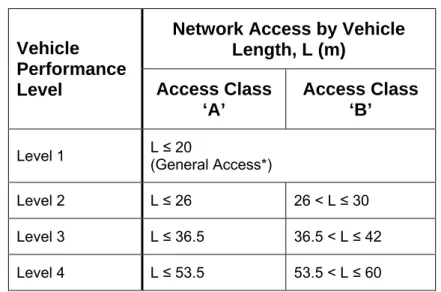
To assist in the application of the Network Classification Guidelines, the maximum vehicle lengths for each road class are as set out below. For heavy vehicles participating in the Scheme that wish to gain access to a specific network level but exceed the maximum permitted length for that level, an individual route assessment will need to be carried out.
Table 8. Network classification by vehicle length
Network Access by Vehicle Length, L (m)
Vehicle Performance
Level Access Class ‘A’
Access Class ‘B’
Level 1 L (General Access*) ≤ 20
Level 2 L ≤ 26 26 < L ≤ 30
Level 3 L ≤ 36.5 36.5 < L ≤ 42
Level 4 L ≤ 53.5 53.5 < L ≤ 60
* General Access is subject to a 50 tonne gross mass limit, posted local restrictions and restrictions or limitations specified by the jurisdiction.