TM TM
Cray XT™ System Overview
U.S. GOVERNMENT RESTRICTED RIGHTS NOTICE
The Computer Software is delivered as "Commercial Computer Software" as defined in DFARS 48 CFR 252.227-7014.
All Computer Software and Computer Software Documentation acquired by or for the U.S. Government is provided with Restricted Rights. Use, duplication or disclosure by the U.S. Government is subject to the restrictions described in FAR 48 CFR 52.227-14 or DFARS 48 CFR 252.227-7014, as applicable.
Technical Data acquired by or for the U.S. Government, if any, is provided with Limited Rights. Use, duplication or disclosure by the U.S. Government is subject to the restrictions described in FAR 48 CFR 52.227-14 or DFARS 48 CFR 252.227-7013, as applicable.
Cray, LibSci, and UNICOS are federally registered trademarks and Active Manager, Cray Apprentice2, Cray Apprentice2 Desktop, Cray C++ Compiling System, Cray CX1, Cray Fortran Compiler, Cray Linux Environment, Cray SeaStar, Cray SeaStar2, Cray SeaStar2+, Cray SHMEM, Cray Threadstorm, Cray X1, Cray X1E, Cray X2, Cray XD1, Cray XMT, Cray XR1, Cray XT, Cray XT3, Cray XT4, Cray XT5, Cray XT5h, Cray XT5m, CrayDoc, CrayPort, CRInform, ECOphlex, Libsci, NodeKARE, RapidArray, UNICOS/lc, UNICOS/mk, and UNICOS/mp are trademarks of Cray Inc.
AMD is a trademark of Advanced Micro Devices, Inc. Copyrighted works of Sandia National Laboratories include: Catamount/QK, Compute Processor Allocator (CPA), and xtshowmesh. GCC is a trademark of the Free Software Foundation, Inc.. This is free software; see the source for copying conditions. There is NO warranty; not even for MERCHANTABILITY or FITNESS FOR A PARTICULAR PURPOSE. Linux is a trademark of Linus Torvalds. Lustre was developed and is maintained by Cluster File Systems, Inc. under the GNU General Public License. MySQL is a trademark of MySQL AB. Opteron is a trademark of Advanced Micro Devices, Inc. PBS Pro and PBS Professional are trademarks of Altair Grid Technologies. SUSE is a trademark of SUSE LINUX Products GmbH, a Novell business. The Portland Group and PGI are trademarks of The Portland Group Compiler Technology, STMicroelectronics, Inc.. TotalView is a trademark of TotalView Technologies, LLC. All other trademarks are the property of their respective owners.
Version 1.0 Published December 2004 Draft documentation to support Cray XT3 early-production systems.
Version 1.1 Published June 2005 Supports Cray XT3 systems running the Cray XT3 Programming Environment 1.1, System Management Workstation (SMW) 1.1, and UNICOS/lc 1.1 releases.
Version 1.2 Published August 2005 Supports Cray XT3 systems running the Cray XT3 Programming Environment 1.2, System Management Workstation (SMW) 1.2, and UNICOS/lc 1.2 releases.
Version 1.3 Published November 2005 Supports Cray XT3 systems running the Cray XT3 Programming Environment 1.3, System Management Workstation (SMW) 1.3, and UNICOS/lc 1.3 releases.
Version 1.4 Published April 2006 Supports Cray XT3 systems running the Cray XT3 Programming Environment 1.4, System Management Workstation (SMW) 1.4, and UNICOS/lc 1.4 releases.
Version 1.5 Published October 2006 Supports general availability (GA) release of Cray XT systems running the Cray XT Programming Environment 1.5, UNICOS/lc 1.5, and System Management Workstation 1.5 releases.
Version 2.0 Published October 2007 Supports general availability (GA) release of Cray XT systems running the Cray XT Programming Environment 2.0, UNICOS/lc 2.0, and System Management Workstation 3.0 releases.
Version 2.1 Published November 2008 Supports general availability (GA) release of Cray XT systems running the Cray XT Programming Environment, Cray Linux Environment (CLE) 2.1, and System Management Workstation 3.1 releases.
Version 2.2 Published July 2009 Supports general availability (GA) release of Cray XT systems running the Cray XT Programming Environment, Cray Linux Environment (CLE) 2.2, and System Management Workstation 4.0 releases.
Contents
Page
Introduction [1] 7
1.1 Cray XT Features . . . 7
1.2 Related Publications . . . 11
1.2.1 Publications for Application Developers . . . 11
1.2.2 Publications for System Administrators . . . 14
Hardware Overview [2] 15 2.1 Basic Hardware Components . . . 15
2.1.1 AMD Opteron Processor . . . 15
2.1.2 DIMM Memory . . . 17
2.1.3 Cray SeaStar Chip . . . 18
2.1.4 System Interconnection Network . . . 19
2.1.5 RAID Disk Storage Subsystems . . . 19
2.2 Nodes . . . 19
2.2.1 Compute Nodes . . . 20
2.2.2 Service Nodes . . . 21
2.3 Blades, Chassis, and Cabinets . . . 22
2.3.1 Blades . . . 22
2.3.2 Chassis and Cabinets . . . 22
Software Overview [3] 25 3.1 CLE Operating System . . . 25
3.1.1 CNL . . . 25
3.2 Lustre File System . . . 26
3.3 Cray Data Virtualization Service (Cray DVS) . . . 27
3.4 Development Environment . . . 27
3.4.1 User Environment . . . 27
3.4.2 Compiling Programs . . . 28
3.4.2.3 GCC Compiler Commands . . . 29
3.4.2.4 PathScale Compiler Commands . . . 30
3.4.3 Using Library Functions . . . 30
3.4.4 Linking Applications . . . 32
3.4.5 Running Applications . . . 32
3.4.5.1 Running Applications Interactively . . . 33
3.4.5.2 Running Batch Jobs . . . 34
3.4.6 Debugging Applications . . . 35
3.4.7 Monitoring and Managing Applications . . . 36
3.4.8 Measuring Performance . . . 36
3.4.8.1 Performance API . . . 36
3.4.8.2 CrayPat . . . 36
3.4.8.3 Cray Apprentice2 . . . 37
3.4.9 Optimizing Applications . . . 38
3.4.10 Using Data Visualization Tools . . . 38
3.5 System Administration . . . 39
3.5.1 System Management Workstation . . . 39
3.5.2 Shared-root File System . . . 39
3.5.3 Lustre File System Administration . . . 39
3.5.4 Configuration and Source Files . . . 40
3.5.5 System Log . . . 41
3.5.6 CMS Log Manager . . . 41
3.5.7 Service Database . . . 41
3.5.8 System Accounting . . . 41
3.5.9 System Activity Reports . . . 42
Cray Hardware Supervisory System (HSS) [4] 43 4.1 HSS Hardware . . . 43
4.1.1 HSS Network . . . 44
4.1.2 System Management Workstation . . . 44
4.1.3 Hardware Controllers . . . 45
4.2 HSS Software . . . 45
4.2.1 Software Monitors . . . 45
Contents
Page
4.3.4 Event Handling . . . 47
Glossary 49 Figures Figure 1. Cray XT5 System . . . 11
Figure 2. Single-core Processor . . . 16
Figure 3. Dual-core Processor . . . 17
Figure 4. Quad-core Processor . . . 17
Figure 5. Hex-core Processor . . . 17
Figure 6. Cray SeaStar Chip . . . 19
Figure 7. Cray XT3 and Cray XT4 Compute Nodes . . . 20
Figure 8. Cray XT5 Compute Node . . . 20
Figure 9. Service Node . . . 21
Figure 10. Chassis and Cabinet (front view) . . . 23
Figure 11. Launching Applications Interactively . . . 34
Figure 12. Running Batch Jobs . . . 35
Introduction [1]
This document provides an overview of Cray XT systems. The intended audiences are application developers and system administrators. Prerequisite knowledge is a familiarity with the concepts of high-performance computing and the architecture of parallel processing systems.
The UNICOS/lc operating system was renamed Cray Linux Environment (CLE). The transition to the new CLE name began in version 2.1 and is complete with this release.
Note: Functionality marked as deferred in this documentation is planned to be implemented in a later release.
1.1 Cray XT Features
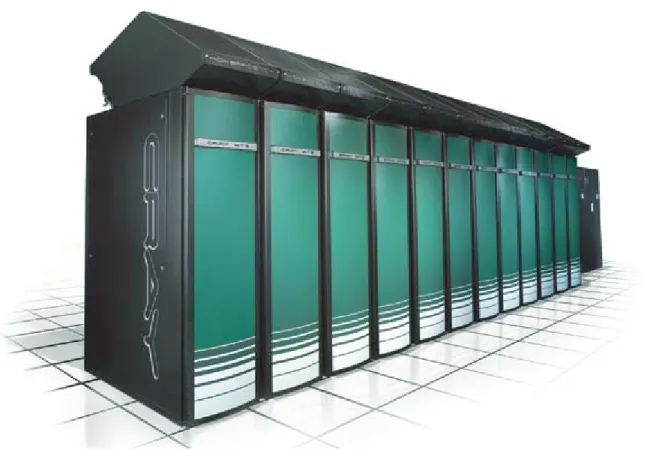
Cray XT supercomputer systems are massively parallel processing (MPP) systems. Cray has combined commodity and open source components with custom-designed components to create a system that can operate efficiently at an immense scale. Cray XT systems are based on the Red Storm technology that was developed jointly by Cray Inc. and the U.S. Department of Energy Sandia National Laboratories. Cray XT systems are designed to run applications that require large-scale processing, high network bandwidth, and complex communications. Typical applications are those that create detailed simulations in both time and space, with complex geometries that involve many different material components. These long-running, resource-intensive applications require a system that is programmable, scalable, reliable, and manageable.
The Cray XT series consists of Cray XT3, Cray XT4, and Cray XT5 systems. The primary differences among the systems are the type and speed of their compute node components (seeCompute Nodes on page 20).
The major features of Cray XT systems are scalability and resiliency:
• Cray XT systems are designed to scale from fewer than 100 to more than 250,000 processors. The ability to scale to such proportions stems from the design of system components:
– The basic component is the node. There are two types of nodes. Service nodes provide support functions, such as managing the user's environment, handling I/O, and booting the system. Compute nodes run user applications. Because processors are inserted into standard sockets, customers can upgrade nodes as faster processors become available.
– Cray XT systems use a simple memory model. Every instance of a distributed application has its own processors and local memory. Remote memory is the memory on the nodes running the associated application instances. There is no shared memory.
– The system interconnection network links compute and service nodes. This is the data-routing resource that Cray XT systems use to maintain high communication rates as the number of nodes increases. Most Cray XT systems use a full 3D torus network topology.
• Cray XT resiliency features include:
– The Node Health Checker (NHC), which performs tests to determine if compute nodes allocated to an application are healthy enough to support running subsequent applications. If not, NHC removes any nodes incapable of running an application from the resource pool.
– Tools that assist administrators in recovering from system or node failures, including a hot backup utility, and boot node failover, and single or multiple compute node reboots.
– Error correction code (ECC) technology, which detects and corrects multiple-bit data transfer errors.
– Lustre failover. When administrators enable Lustre automatic failover, Lustre services switch to standby services when the primary node fails or when Lustre services are temporarily shut down for maintenance.
– Cray XT system cabinets with only one moving part (a blower that cools the components) and redundant power supplies, reducing the likelihood of cabinet failure.
Introduction [1]
– Diskless nodes. The availability of a node is not tied to the availability of a moving part.
– Multiple redundant RAID controllers, with automatic failover capability and multiple Fibre Channel connections to disk storage.
The major components of Cray XT systems are: • Application development tools, comprising:
– Cray Application Development Environment (CADE), comprising: • Message Passing Toolkit (MPI, SHMEM)
• Math and science libraries (LibSci, PETSc, ACML, FFTW, Fast_mv) • Data modeling and management tools (NetCDF, HDF5)
• GNU debugger (lgdb)
• GCC C, C++, and Fortran compilers
• Java (for developing service node programs) • Checkpoint/restart
• CrayPat performance analysis tool
– Cray Compiling Environment (CCE), comprising the Cray C, C++ (Deferred implementation), and Fortran compilers
– Optional products, comprising:
• C, C++, and Fortran compilers from PGI and PathScale • glibc library (the compute node subset)
• UPC and OpenMP parallel programming models • aprunapplication launch utility
• Workload management Systems (PBS Professional, Moab/Torque) • TotalView debugger
• Cray Apprentice2 performance data visualization tool
• Cray Application Development Supplement (CADES) for stand-alone Linux application development platforms
• Operating system services. The Cray XT operating system, CLE, is tailored to the requirements of service and compute nodes. A full-featured SUSE Linux operating system runs on service nodes, and a lightweight kernel, CNL, runs on compute nodes.
• Parallel file system. The Cray XT parallel file system, Lustre, which scales to thousands of clients and petabytes of data.
• System management and administration tools:
– System Management Workstation (SMW), the single point of control for system administration.
– Hardware Supervisory System (HSS), which monitors the system and handles component failures. HSS is independent of computation and service hardware components and has its own network.
– Cray Management Services (CMS), which provides the infrastructure to the Application Level Placement Scheduler (ALPS) for a fast cache of node attributes, reservations, and claims.
– Comprehensive System Accounting (CSA), a software package that performs standard system accounting processing. CSA is open-source software that includes changes to the Linux kernel so that the CSA can collect more types of system resource usage data than under standard Fourth Berkeley Software Distribution (BSD) process accounting.
An additional CSA interface allows the project database to use customer-supplied user, account, and project information residing on a separate Lightweight Directory Access Protocol (LDAP) server.
Introduction [1]
Figure 1. Cray XT5 System
1.2 Related Publications
The Cray XT system runs with a combination of Cray proprietary, third-party, and open source products, as documented in the following publications.
1.2.1 Publications for Application Developers
• Cray XT System Overview (this manual)
• Cray XT Programming Environment User's Guide
• Cray Application Developer's Environment Installation Guide • Cray XT System Software Release Overview
• Cray C and C++ Reference Manual • Cray Fortran Reference Manual
• PGI Tools Guide • PGI Fortran Reference
• PGI compiler command options man pages: pgcc(1),pgCC(1),pgf95(1) • GCC manuals: http://gcc.gnu.org/onlinedocs/
• GCC compiler command options man pages:gcc(1),g++(1),gfortran(1) • PathScale manuals: http://www.pathscale.com/docs.html
• PathScale compiler command options man pages: pathcc(1),pathCC(1),
path95(1),eko(7)
• Cray XT compiler driver commands man pages: cc(1),CC(1),ftn(1) • Modules utility man pages: module(1),modulefile(4)
• Application launch command man page: aprun(1) • Parallel programming models:
– Cray MPICH2 man pages (read theintro_mpi(3) man page first) – Cray SHMEM man pages (read theintro_shmem(3) man page first) – OpenMP documentation: http://www.openmp.org/
– Cray UPC man pages (read theintro_upc(3c) man page first) Unified Parallel C (UPC) documents: Berkeley UPC
website (http://upc.lbl.gov/docs/) and Intrepid UPC website
(http://www.intrepid.com/upc/cray_xt3_upc.html).
• Cray scientific library, XT-LibSci, documentation: – Basic Linear Algebra Subroutines (BLAS) man pages – LAPACK linear algebra man pages
– ScaLAPACK parallel linear algebra man pages
– Basic Linear Algebra Communication Subprograms (BLACS) man pages – Iterative Refinement Toolkit (IRT) man pages (read theintro_irt(3) man
page first)
– SuperLU sparse solver routines guide (SuperLU Users' Guide) • AMD Core Math Library (ACML) manual
Introduction [1]
• Portable, Extensible Toolkit for Scientific Computation (PETSc) library, an open source library of sparse solvers. See theintro_petsc(3) man page and
http://www-unix.mcs.anl.gov/petsc/petsc-as/index.html
• NetCDF documentation (http://www.unidata.ucar.edu/software/netcdf/) • HDF5 documentation (http://www.hdfgroup.org/HDF5/whatishdf5.html) • Lustrelfs(1) man page
• PBS Professional 9.0 User's Guide
• PBS Professional man pages (qsub(1B) ,qstat(1B), andqdel(1B)) • Moab/Torque documentation (http://www.clusterresources.com/) • TotalView documentation (http://www.totalviewtech.com/)
• GNU debugger documentation (see thelgdb(1) man page and the GDB User Manual athttp://www.gnu.org/software/gdb/documentation/).
• PAPI man pages (read theintro_papi(3) man page first) • PAPI manuals (seehttp://icl.cs.utk.edu/papi/)
• Using Cray Performance Analysis Tools
• CrayPat man pages (read theintro_craypat(1) man page first) • Cray Apprentice2 man page (app2(1))
• CLE man pages
• SUSE LINUX man pages
• Linux documentation (see the Linux Documentation Project at
1.2.2 Publications for System Administrators
• Cray XT System Overview (this manual) • Cray XT System Software Release Overview
• Cray Application Developer's Environment Installation Guide • Cray XT System Software Installation and Configuration Guide
• Cray System Management Workstation (SMW) Software Installation Guide • Cray XT System Management manual
• Using Cray Management Services (CMS) • CLE man pages
• SUSE LINUX man pages
• HSS man pages (read thextcli(8) man page first)
• Lustre documentation (see Managing Lustre on a Cray XT System and
http://manual.lustre.org)
• Linux documentation (see the Linux Documentation Project at
Hardware Overview [2]
Cray XT system hardware consists of computation components, service components, the system interconnection network, RAID disk storage systems, and HSS
components. This chapter describes all hardware components except HSS hardware, which is described inChapter 4, Cray Hardware Supervisory System (HSS) on
page 43.
2.1 Basic Hardware Components
The Cray XT system include the following hardware components: • AMD Opteron processors
• Dual in-line memory modules (DIMMs)
• System interconnection network including Cray SeaStar chips • RAID disk storage subsystems
2.1.1 AMD Opteron Processor
Cray XT systems use AMD Opteron processors. Each Cray XT3 compute node has one single- or core processor. Each Cray XT4 compute node has one dual-or quad-cdual-ore processdual-or. Each Cray XT5 compute node has two quad- dual-or hex-cdual-ore processors, connected by HyperTransport links.
All Cray XT service nodes use the same processors and memory as a Cray XT3 compute node.
Opteron processors feature:
• Full support of the x86 instruction set.
• Full compatibility with AMD Socket 940 design (Cray XT3 systems), AMD Socket AM2 design (Cray XT4 systems), and AMD Socket F design (Cray XT5 systems).
• Out-of-order execution and the ability to issue instructions simultaneously. • Registers and a floating-point unit that support full 64-bit IEEE floating-point
operations.
• An integer processing unit that performs full 64-bit integer arithmetic. • Performance counters that can be used to monitor the number or duration of
processor events, such as the number of data cache misses or the time it takes to return data from memory after a cache miss.
• A memory controller that uses error correction code (ECC) for memory protection.
• A HyperTransport interface that connects to the SeaStar chip.
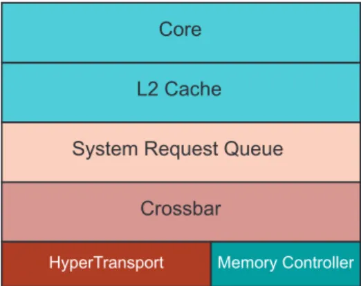
Multicore processors have two, four, or six computation engines (referred to as cores or CPUs). Each core has its own execution pipeline and the resources required to run without blocking resources needed by other processes. Because multicore processors can run more tasks simultaneously, they can increase overall system performance. The trade-offs are that the cores share local memory bandwidth and system interconnection bandwidth.
The following figures show the components of Opteron processors.
Figure 2. Single-core Processor
L2 Cache Core
System Request Queue
Crossbar
Hardware Overview [2]
Figure 3. Dual-core Processor
L2 Cache Core 0
System Request Queue
Crossbar
HyperTransport Memory Controller
Core 1
L2 Cache
Figure 4. Quad-core Processor
System Request Queue Crossbar Core 0 Core 1 L2 Cache L2 Cache L2 Cache L2 Cache L3 Cache
HyperTransport Memory Controller
Core 2 Core 3
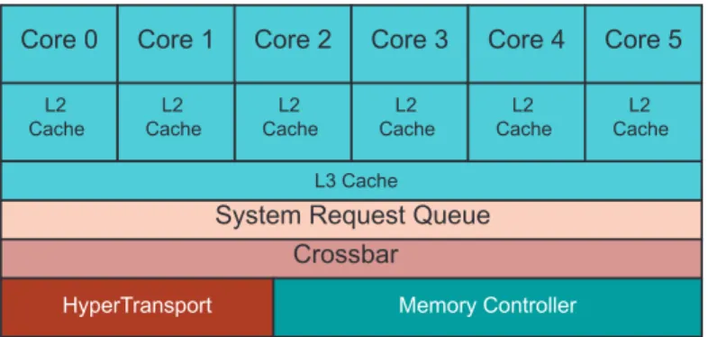
Figure 5. Hex-core Processor
System Request Queue Crossbar Core 0 Core 1 L2 Cache L2 Cache L2 Cache L2 Cache L3 Cache
HyperTransport Memory Controller
Core 2 Core 3 L2 Cache L2 Cache Core 4 Core 5
2.1.2 DIMM Memory
Cray XT systems use Double Data Rate Dual In-line Memory Modules (DDR DIMMs). Cray XT3 systems use 1 GB, 2 GB, or 4 GB DDR1 DIMMs. Cray XT4 systems use 1 GB or 2 GB DDR2 DIMMs. With four DIMM slots per processor, the maximum physical memory is 16 GB per node on Cray XT3 systems and 8 GB per node on Cray XT4 systems.
Cray XT5 systems use 1 GB, 2 GB, or 4 GB DDR2 DIMMs. With four DIMM slots per processor and eight DIMM slots per node, the maximum physical memory is 32 GB per node.
The minimum amount of memory for service nodes is 2 GB. Service nodes use the same type of memory as a Cray XT3 compute node.
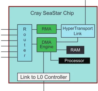
2.1.3 Cray SeaStar Chip
The Cray SeaStar application-specific integrated circuit (ASIC) chip is the system's message handler, offloading communications functions from the AMD Opteron processors. Cray XT3 compute nodes use SeaStar 1 chips. Cray XT4 and Cray XT5 compute nodes use SeaStar 2 chips. Service nodes can use either SeaStar 1 or SeaStar 2 chips.
A SeaStar chip contains:
• HyperTransport Links, which connect SeaStar to the AMD Opteron processor. • A Direct Memory Access (DMA) engine, which manages the movement of
data to and from node memory. The DMA engine is controlled by an on-board processor.
• A router, which together with the other SeaStar routers connects the chip to the system interconnection network. For more information, seeSystem
Interconnection Network on page 19.
• A low-level message passing interface called Portals, which provides a data path from an application to memory. Portions of the interface are implemented in Cray SeaStar firmware, which transfers data directly to and from user memory. The firmware runs on the embedded processor and RAM within the SeaStar chip. • A link to a blade control processor (also known as an L0 controller). Blade
control processors are used for booting, monitoring, and maintenance (see
Hardware Controllers on page 45).
• A Remote Memory Access (RMA) engine for use in Cray XMT compute nodes. This engine provides an interface to the remote shared memory framework for that architecture.
Hardware Overview [2]
Figure 6illustrates the hardware components of the Cray SeaStar chip.
Figure 6. Cray SeaStar Chip
R o u t e r RMA HyperTransport Link RAM Processor
Cray SeaStar Chip
DMA Engine
Link to L0 Controller
2.1.4 System Interconnection Network
The system interconnection network is the communications center of the Cray XT system. The network consists of the Cray SeaStar routers, links and the cables that connect the compute and service nodes.
The network uses a Cray proprietary protocol to provide fast node-to-node message passing and fast I/O to and from a global, shared file system. The network
enables the system to achieve an appropriate balance between processor speed and interconnection bandwidth.
2.1.5 RAID Disk Storage Subsystems
Cray XT systems use two types of RAID subsystems for data storage. System RAID stores the boot image and system files. File system RAID is managed by the Lustre parallel file system; it holds root and user files.
Data on system RAID is not globally accessible. Data on file system RAID is globally accessible by default.
2.2 Nodes
Cray XT processing components combine to form a node. The Cray XT system has two types of nodes: compute nodes and service nodes. Each node is a logical
2.2.1 Compute Nodes
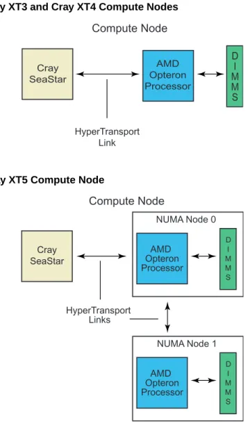
Compute nodes run application programs. A Cray XT3 compute node consists of a single- or dual-core AMD Opteron processor, DDR1 DIMM memory, and a Cray SeaStar 1 chip. A Cray XT4 compute node consists of a dual- or quad-core AMD Opteron processor, DDR2 DIMM memory, and a Cray SeaStar 2 chip. A Cray XT5 compute node consists of two quad or hex-core NUMA nodes and one Cray SeaStar 2 chip. Each NUMA node has a quad- or hex-core processor and NUMA-node-local DDR2 DIMM memory. They are referred to as NUMA nodes because of the slight delay in accessing NUMA-node-local memory versus NUMA-node-remote memory.
Figure 7. Cray XT3 and Cray XT4 Compute Nodes Compute Node Cray SeaStar HyperTransport Link AMD Opteron Processor D I M M S
Figure 8. Cray XT5 Compute Node
AMD Opteron Processor HyperTransport Links Compute Node Cray SeaStar NUMA Node 1 D I M M S AMD Opteron Processor NUMA Node 0 D I M M S AMD Opteron Processor
Hardware Overview [2]
2.2.2 Service Nodes
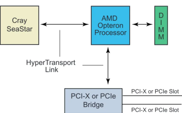
Service nodes handle system functions such as user login, I/O, and network management. Each service node contain a single- or dual-core processor, DDR1 DIMM memory, and a SeaStar 1 or SeaStar 2 chip. In addition, each service node contains two PCI-X or PCIe slots for optional interface cards.
Cray XT systems include several types of service nodes, defined by the function they perform.
• Login nodes. Users log in to the system through login nodes. Each login node includes one or two Ethernet network interface cards that connect to an Ethernet-based local area network, to which user workstations are connected. • Network service nodes. Each network service node contains a PCI-X or PCIe card
that can be connected to customer network storage devices.
• I/O nodes. Each I/O node uses one or two fibre channel cards to connect to Lustre-managed RAID storage.
• Boot nodes. Each system requires one boot node. A boot node contains one fibre channel card which is either PCI-X or PCIe. The fibre channel card connects to the RAID subsystem, and an Ethernet network interface card connects to the System Management Workstation (SMW). Most systems have two boot nodes: a primary and a backup.
• Service database (SDB) nodes. Each SDB node contains a fibre channel card to connect to the SDB file system. The SDB node manages the state of the Cray XT system.
For a description of the types of service nodes, seeCLE Operating System on
page 25.
Figure 9. Service Node
AMD Opteron Processor D I M M PCI-X or PCIe Bridge Cray SeaStar HyperTransport Link
PCI-X or PCIe Slot
2.3 Blades, Chassis, and Cabinets
This section describes the main physical components of the Cray XT system and their configurations.
2.3.1 Blades
Whereas the node is the logical building block of the Cray XT system, the basic physical component and field-replaceable unit is the blade. Any Cray XT blade has a mezzanine, also a field-replaceable unit, containing four Cray SeaStar chips. There are two types of blades: compute blades and service blades.
A compute blade consists of four compute nodes, voltage regulator modules, and an L0 controller. The L0 controller is an HSS component; for more information, see
Chapter 4, Cray Hardware Supervisory System (HSS) on page 43.
A service blade consists of two service nodes, voltage regulator modules, PCI-X or PCIe cards, and an L0 controller. Although a service blade has two nodes, it has four SeaStar chips to allow for a common board design and to simplify the interconnect configurations. Several different PCI-X or PCIe cards are available to provide Fibre Channel interfaces to file system RAID, GigE interfaces to user workstations, and 10 GigE interfaces to external networks.
2.3.2 Chassis and Cabinets
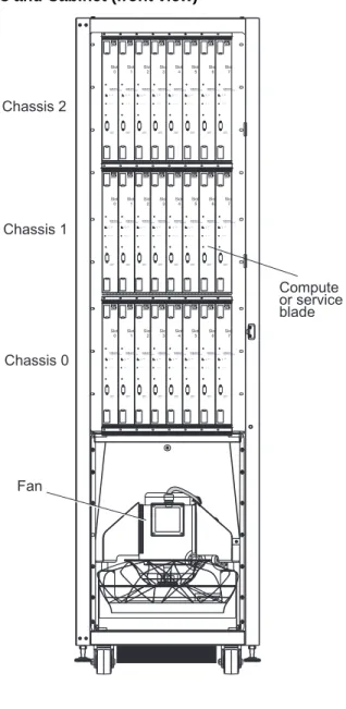
Each cabinet contains three vertically stacked chassis (or cages), and each chassis contains eight vertically mounted blades. A cabinet can contain compute blades, service blades, or a combination of compute and service blades. There are different cabinet types: Cray XT3, Cray XT4, Cray XT5, Cray XT5-HE air cooled, and Cray XT5-HE liquid cooled. The primary difference is increased power and cooling capacity for newer blade types.
Customer-provided three-phase power is supplied to the cabinet Power Distribution Unit (PDU). The PDU routes power to the cabinet's power supplies, which distribute 48 VDC to each of the chassis in the cabinet.
Hardware Overview [2]
All cabinets have redundant power supplies. The PDU, power supplies, and the cabinet control processor (L1 controller) are located at the rear of the cabinet.Figure 10shows the basic components of an air-cooled cabinet.
Figure 10. Chassis and Cabinet (front view)
Fan Chassis 2 Compute or service blade Chassis 1 Chassis 0
COMPUTE MODULECOMPUTE MODULECOMPUTE MODULECOMPUTE MODULECOMPUTE MODULE COMPUTE MODULE
HOT SWAP L0
HOT SWAP L0
L0 HOT SWAPL0 HOT SWAPL0 HOT SWAPL0 HOT SWAPL0
CONSOLE 9600:8N1 CONSOLE 9600:8N1 CONSOLE 9600:8N1 CONSOLE 9600:8N1 CONSOLE9600:8N1 CONSOLE 9600:8N1 (...) L0(...) L0(...) L0(...) L0(...) L0(...) Slot 0 Slot 1 Slot 2 Slot 3 Slot 4 Slot 5 Slot 6 COMPUTE MODULE HOT SWAP L0 CONSOLE 9600:8N1 L0(...) HOT SWAPL0 CONSOLE 9600:8N1 CONSOLE 9600:8N1 CONSOLE 9600:8N1 CONSOLE 9600:8N1 CONSOLE 9600:8N1 CONSOLE9600:8N1 CONSOLE 9600:8N1 CONSOLE9600:8N1 CONSOLE9600:8N1 L0(...) Slot 7 COMPUTE MODULE
COMPUTE MODULECOMPUTE MODULECOMPUTE MODULECOMPUTE MODULECOMPUTE MODULE COMPUTE MODULECOMPUTE MODULE
HOT SWAP L0 L0
HOT SWAP
L0 HOT SWAPL0 HOT SWAPL0 HOT SWAPL0 HOT SWAPL0 HOT SWAPL0 (...) L0(...) L0(...) L0(...) L0(...) L0(...) L0(...) Slot 0 Slot 1 Slot 2 Slot 3 Slot 4 Slot 5 Slot 6 COMPUTE MODULE HOT SWAP L0 L0(...) Slot 7 COMPUTE MODULE HOT SWAPL0 L0 CONSOLE 9600:8N1 CONSOLE 9600:8N1 L0 L0(...) Slot 7
COMPUTE MODULECOMPUTE MODULECOMPUTE MODULE
HOT SWAP L0 HOT SWAPL0 HOT SWAPL0
CONSOLE 9600:8N1 CONSOLE 9600:8N1 CONSOLE 9600:8N1 L0(...) L0(...) L0(...) Slot 2 Slot 3 Slot 4 Slot 5 COMPUTE MODULE HOT SWAP L0 CONSOLE 9600:8N1 L0(...) COMPUTE MODULE HOT SWAP (...) Slot 6
COMPUTE MODULECOMPUTE MODULE
HOT SWAP L0 L0 HOT SWAP L0 CONSOLE 9600:8N1 CONSOLE 9600:8N1 (...) L0(...) Slot 0 Slot 1
Software Overview [3]
Cray XT systems run a combination of Cray-developed software, third-party software, and open source software. The software is optimized for applications that have fine-grain synchronization requirements, large processor counts, and significant communication requirements.
This chapter provides an overview of the Cray Linux Environment (CLE) operating system, the Lustre file system, the application development environment, and system administration tools. For a description of HSS software, seeChapter 4, Cray
Hardware Supervisory System (HSS) on page 43.
3.1 CLE Operating System
The Cray XT operating system, Cray Linux Environment (CLE), is a distributed system of service-node and compute-node components.
The CLE compute node kernel, CNL, supports all compute node processes. Service nodes perform the functions needed to support users, administrators, and applications running on compute nodes. There are five basic types of service nodes: login, network, I/O, boot, and SDB. Service nodes run a full-featured version of SUSE LINUX.
Above the operating system level are specialized daemons and applications that perform functions unique to each service node.
3.1.1 CNL
CNL is the Cray XT lightweight compute node kernel. It includes a run time environment based on the SUSE Linux Enterprise Server (SLES) distribution and the SLES kernel with Cray specific modifications. Cray has configured the kernel to eliminate device drivers for hardware not supported on Cray XT systems. Other features and services not required by Cray XT applications have also been configured out of the kernel.
CNL features:
• Scalability. Only the features required to run high performance applications are available on the compute nodes. Other features and services are available from service nodes.
• Minimized OS jitter. Cray has configured and tuned the kernel to minimize processing delays caused by inefficient synchronization.
• Minimized memory footprint. Cray has configured the kernel and the ramfs-based root file system to use a minimum amount of memory on each node in order to maximize the amount of memory available for applications.
• Non-Uniform Memory Access (NUMA). NUMA architecture is particularly beneficial to applications that run on Cray XT5 compute nodes (see
Compute Nodes on page 20). NUMA is much more efficient than symmetric
multiprocessing (SMP) because data is tightly coupled between processor and memory pairs.
• Application networking (sockets). • POSIX system calls.
• POSIX threads functions.
A separate service, the Application Level Placement Scheduler (ALPS), handles application launch, monitoring, and signaling and coordinates batch job processing with a workload management system.
3.2 Lustre File System
Lustre is the parallel file system for Cray XT applications. Lustre features high-performance, scalability, and POSIX compliance. I/O nodes host Lustre. Lustre is implemented as a set of Linux-loadable modules and uses Portals and an object-oriented architecture for storing and retrieving data.
Lustre separates file metadata from data objects. Each instance of a Lustre file system consists of Object Storage Servers (OSSs) and a Metadata Server (MDS). Each OSS hosts one or more Object Storage Targets (OSTs). Lustre OSTs are backed by RAID storage. Applications store data on OSTs; files can be striped across multiple OSTs. Cray XT systems implement Lustre automatic failover and administrator-supported failback MDSs and OSTs.
Software Overview [3]
Lustre's I/O operations are transparent to the application developer. The I/O functions available to the application developer—Fortran, C, and C++ I/O calls; C and C++ stride I/O calls; and system I/O calls—are converted to Lustre driver calls by the virtual file system switch (Linux VFS).
For further information about Lustre, see Managing Lustre on a Cray XT System and
http://manual.lustre.org.
3.3 Cray Data Virtualization Service (Cray DVS)
Cray DVS is a distributed network service that gives compute node applications transparent access to file systems on I/O nodes. Applications can read and write data to the user's home directory, and users can access files over a network as if they were local.
Cray DVS supports access to VFS-based, POSIX-compliant file systems. However, DVS is not a file system, but an I/O forwarding service. Cray DVS provides I/O scalability to large numbers of nodes, far beyond the typical number of clients supported by a single NFS server.
For additional information, see the Cray XT System Software Installation and Configuration Guide and Introduction to Cray Data Virtualization Service.
3.4 Development Environment
Application development software is the set of software products and services that programmers use to build and run applications on compute nodes.
3.4.1 User Environment
The user environment is similar to the environment on a typical Linux workstation. Users log in to a Cray XT login node or a stand-alone Linux workstation and compile and link their applications. They run their applications on Cray XT compute nodes. The Cray Application Developer's Environment Supplement (CADES) contains the additional components required in order to install and use CADE on standalone Linux systems.
Before starting to develop applications, the user:
1. Sets up a secure shell. The Cray XT system usessshandssh-enabled
applications for secure, password-free remote access to login nodes. Before using
sshcommands, the user needs to generate an RSA authentication key.
2. Loads the appropriate modules. The Cray XT system uses the Modules utility to support multiple versions of software, such as compilers, and to create integrated software packages. As new versions of the supported software become available, they are added automatically to the Programming Environment, and earlier versions are retained to support legacy applications.
For details, see the Cray XT Programming Environment User's Guide and the
module(1) andmodulefile(4) man pages.
3.4.2 Compiling Programs
The Cray XT system Programming Environment includes Cray compilers and compiler suites from The Portland Group (PGI), the GNU Compiler Collection (GCC), and PathScale.
The compilers translate C, C++, and Fortran source programs into Cray XT object files. Developers can use interlanguage communication functions to create Fortran programs that call C or C++ routines and C or C++ programs that call Fortran routines.
The command used to invoke a compiler, called a compilation driver, can be used to apply options at the compilation unit level. Fortran directives and C or C++ pragmas apply options to selected portions of code or alter the effects of command-line options.
In addition to the Cray, PGI, GCC, and PathScale compilers, the Cray XT
Programming Environment includes the Java compiler for developing applications to run on service nodes. For details, seehttp://java.sun.com/javase/6/docs/.
3.4.2.1 Cray Compiler Commands
The following Cray compiler commands are available:
Cray Compiler Command
C cc
Software Overview [3]
See thecc(1),CC(1), orftn(1) man page for information about the compiler driver command options. See thecraycc(1),crayCC(1) (Deferred implementation), orcrayftn(1) man page for details about Cray compiler options. For further information, see the Cray C and C++ Reference Manual, Cray Fortran Reference Manual, and Cray XT Programming Environment User's Guide.
3.4.2.2 PGI Compiler Commands
The following PGI compiler commands are available:
PGI Compiler Command
C cc
C++ CC
Fortran 90/95 ftn
Note: Users should not invoke a PGI compiler directly using thepgcc,pgCC, or
pgf95command. The resulting executable will not run on the Cray XT system. Thecc(1),CC(1), andftn(1) man pages contain information about the compiler driver commands, whereas thepgcc(1),pgCC(1), andpgf95(1) man pages describe the PGI compiler command options.
For further information, see the Cray XT Programming Environment User's Guide. 3.4.2.3 GCC Compiler Commands
The following GCC compiler commands are available:
GCC Compiler Command
C cc
C++ CC
Fortran 90 ftn
Note: Users should not invoke a GCC compiler directly using thegcc,g++, or
gfortrancommand. The resulting executable will not run on the Cray XT system.
Thecc(1),CC(1), andftn(1) man pages contain information about the compiler driver commands, whereas thegcc(1),g++(1), andgfortran(1) man pages describe the GCC compiler command options.
3.4.2.4 PathScale Compiler Commands
The following PathScale compiler commands are available:
PathScale Compiler Command
C cc
C++ CC
Fortran 90/95 ftn
Note: Users should not invoke a PathScale compiler directly using thepathcc,
pathCC, orpath95command. The resulting executable will not run on the Cray XT system.
Thecc(1),CC(1), andftn(1) man pages contain information about the compiler driver commands, while thepathcc(1),pathCC(1),path95(1), andeko(7) man pages contain descriptions of the PathScale compiler command options.
For further information, see the Cray XT Programming Environment User's Guide.
3.4.3 Using Library Functions
Developers can use C, C++, and Fortran library functions and functions from the following libraries:
• GNU C Language Runtime Library (glibc) functions.
• Cray MPICH2, Cray SHMEM, OpenMP, and UPC functions. MPICH2 and SHMEM use Portals functions for message passing; the Portals interface is transparent to the application programmer.
MPICH2 is an implementation of MPI-2 by the Argonne National Laboratory Group. The dynamic process (spawn) functions in Cray MPICH2 are not supported at this time, but otherwise the libraries are fully MPI 2.0 compliant. Cray SHMEM routines are similar to the Cray MPICH2 routines; they pass data between cooperating parallel processes. Cray SHMEM routines can be used in programs that perform computations in separate address spaces and explicitly pass data to and from different processing elements in the program.
OpenMP is an industry-standard, portable model for shared-memory parallel programming. In addition to library routines, OpenMP provides Fortran directives
Software Overview [3]
The Cray, PGI, and GCC C compilers supprt UPC.
The Cray C compiler supports the UPC Language Specification 1.2 and Cray-specific functions.
The PGI and GCC C compilers support Cray XT-UPC, which contains the following front ends:
– Berkeley UPC translator, a UPC-to-C translator based on Open64. – Intrepid GCCUPC, a UPC-to-assembly compiler based on GNU GCC. Both front ends generate code that is linked with the Berkeley UPC run time library (UPCR) and communication system from Berkeley.
• Cray XT LibSci scientific libraries. XT-LibSci contains:
– Basic Linear Algebra Subroutines (BLAS) and LAPACK linear algebra routines
– ScaLAPACK and Basic Linear Algebra Communication Subprograms (BLACS) routines
– Iterative Refinement Toolkit (IRT), a library of factorization routines, solvers, and tools that can be used to solve systems of linear equations more efficiently than the full-precision solvers in Cray XT-LibSci or ACML.
– SuperLU, a set of routines that solve large, sparse, nonsymmetric systems of linear equations. XT-LibSci library routines are written in C but can be called from Fortran, C, or C++ programs.
– CRay Adaptive Fast Fourier Transform (CRAFFT), a library of Fortran subroutines that compute the discrete Fourier transform in one, two, or three dimensions; of arbitrary input size; and of both real and complex data. CRAFFT provides a simplified interface to FFT and allows the FFT library itself to choose the fastest FFT kernel.
• Portable, Extensible Toolkit for Scientific Computation (PETSc), an open source library of sparse solvers.
• AMD Core Math Library (ACML), which includes:
– A suite of Fast Fourier Transform (FFT) routines for single-precision, double-precision, single-precision complex, and double-precision complex data types.
– Fast scalar, vector, and array math transcendental library routines optimized for high performance.
• The Programming Environment includes the 2.1.5 and 3.1.1 releases of FFTW. FFTW is a C subroutine library with Fortran interfaces for computing the discrete Fourier transform in one or more dimensions, of arbitrary input size, and of both real and complex data (as well as of even/odd data, such as the discrete cosine/sine transforms). The Fast Fourier Transform (FFT) algorithm is applied for many problem sizes. Distributed memory parallel FFTs are available only in FFTW 2.1.5. For further information, see theintro_fftw2(3) and
intro_fftw3(3) man pages.
• Fast_mv, a library of high-performance math intrinsic functions. The functions can be used in PGI and PathScale applications. For further information, see the
intro_fast_mv(3) man page.
3.4.4 Linking Applications
After correcting compilation errors, the developer again invokes the compilation driver, this time specifying the application's object files (filename.o) and libraries (filename.a) as required.
The linker extracts the library modules that the program requires and creates the executable file (nameda.outby default).
3.4.5 Running Applications
There are two methods of running applications: interactively and through application launch commands in batch job scripts. The user can run an application interactively by:
• Using theapruncommand to launch applications on compute nodes the administrator has configured for interactive use.
• Using theqsub -Icommand to initiate an interactive session and then running an application interactively using theapruncommand.
The developer uses a workload management system (WMS) to run batch jobs. PBS Professional, Moab/Torque, and Platform LSF (Deferred implementation) are networked subsystems for submitting, monitoring, and controlling batch jobs. A batch job is typically a shell script and attributes that provide resource and control information about the job. Batch jobs are scheduled for execution at a time chosen by the subsystem according to a defined policy and the availability of resources.
A WMS server maintains job queues. Each queue holds a group of jobs available for execution, and each job has a set of user-specified resource requirements.
Software Overview [3]
Developers who want to launch an application only on nodes with certain attributes can use thecnselectcommand. Among the attributes are node ID, number of cores per node (1, 2, 4, or 8), amount of node memory, page size, and CPU clock rate. Thecnselectutility uses the service database (SDB) to generate a candidate list of nodes. Developers can include this list or a subset of it onaprunorqsub
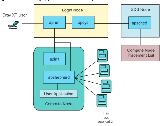
commands to launch applications on compute nodes with those attributes. 3.4.5.1 Running Applications Interactively
To launch an application interactively, the user enters theapruncommand, specifying the application executables and the compute node resources they require. Theaprunclient sends the request to theapsysserver, which forwards it to the
apschedagent running on a service node. Theapschedagent gets the compute node placement list, reserves the nodes needed for the application, and relays the placement list toaprun. On Cray XT4 and Cray XT5 compute nodes, support for non-uniform processing element (PE) placement is supported. This means that
apschedwill attempt to place the maximum amount of PEs per computer node. This potentially improves performance by allowing systems with both types of compute blades to exploit all resources rather than leave some nodes under-utilized. Theaprunclient then sends the placement list and the executable binary data to the
apinitdaemon running on the first node assigned to the application.
On each node allocated to the application, anapinitdaemon creates an application shepherd to manage the processes of the application on that node. The application shepherd on the first assigned node propagates the node placement list and the executable to the compute nodes using a fan-out tree and passes control to the application.
While the application is running, application shepherds monitor the application processes. If theaprunclient or an application instance catches a signal, the signal is propagated to all processing elements. Applications rely onaprunto manage the standard input, standard output, and standard error streams and handle signal management.
Figure 11. Launching Applications Interactively
Cray XT User Login Node aprun Fan out application apsys apsched SDB Node Compute Node Placement List Compute Node apinit apshepherd User Application
3.4.5.2 Running Batch Jobs
The Cray XT system uses a workload management system to launch batch jobs. The user creates a script containingapruncommands, then enters theqsubcommand to submit the job to a WMS server.
The WMS server uses the apbasilinterface to reserve the nodes required for the job, then processes the job scripts. When the WMS encounters theaprun
command(s) in the script, control is transferred to ALPS for application propagation and launch.
Software Overview [3]
Figure 12. Running Batch Jobs
Cray XT User Login Node qsub Fan out application Login Shell Login Node aprun apsched SDB Node Compute Node Placement List Compute Node WMS apinit apshepard apbasil User Application
3.4.6 Debugging Applications
The Cray XT system supports the TotalView debugger for single-process and mutiprocess debugging and the GNUlgdbdebugger for single-process applications. The TotalView debugger, available from TotalView Technologies, LLC, provides source-level debugging of applications. It is compatible with the PGI, GCC, and PathScale compilers.
TotalView can debug applications running on 1 to 4096 compute nodes, providing visibility and control into each process individually or by groups. It also supports access to MPI-specific data, such as the message queues.
TotalView typically is run interactively. To debug a program using TotalView, the developer invokes TotalView either from the graphical interface (totalview) or the command line (totalviewcli). TotalView parses the command to get the number of nodes requested, then makes a node allocation request. TotalView directsaprun
to load but not start the application. Theaprunutility loads the application onto the compute nodes, after which TotalView can perform initial setup before instructing
aprunto start the application.
For more information about TotalView, see the Cray XT Programming Environment User's Guide, thetotalview(1) man page, and TotalView documentation at
http://www.totalviewtech.com/Documentation/. To find out what levels of the
compilers TotalView supports, see the TotalView Platforms and System Requirements document at the TotalView website.
For more information aboutlgdb, see the Cray XT Programming Environment User's Guidelgdb(1) man page.
3.4.7 Monitoring and Managing Applications
ALPS provides commands for monitoring and managing applications. Theapstat
command reports the status of applications, including the number of processing elements, number of threads, a map of the application's address space, and a map showing the placement of team members. Theapkillcommand sends a kill signal to an application team.
For more information, see theapstat(1) andapkill(1) man pages.
3.4.8 Measuring Performance
The Cray XT system provides tools for collecting, analyzing, and displaying performance data.
3.4.8.1 Performance API
The Performance API (PAPI) from the University of Tennessee and Oak Ridge National Laboratory is a standard interface for accessing hardware performance counters. A PAPI event set maps AMD Opteron processor hardware counters to a list of events, such as Level 1 data cache misses, data translation lookaside buffer (TLB) misses, and cycles stalled waiting for memory accesses. Developers can use the API to collect data on those events.
Software Overview [3]
Sampling experiments capture information at user-defined time intervals or when a predetermined event occurs, such as the overflow of a user-specified hardware performance counter. Tracing experiments capture information related to both predefined and user-defined function entry points, such as the number of times a particular MPI function is called and the amount of time the program spends performing that function.
The developer uses thepat_buildcommand to instrument programs. No recompilation is needed to produce the instrumented program. Alternatively, the developer can use thepat_hwpccommand to instrument the program for collecting predefined hardware performance counter information, such as cache usage data. After instrumenting a program, the developer sets environment variables to control run time data collection, runs the instrumented program, then uses thepat_report
command to either generate a report or export the data for use in Cray Apprentice2 or other applications.
3.4.8.3 Cray Apprentice2
Cray Apprentice2 is an interactive X Window System tool for displaying performance analysis data captured during program execution.
Cray Apprentice2 identifies many potential performance problem areas, including the following conditions:
• Load imbalance • Excessive serialization • Excessive communication • Network contention
• Poor use of the memory hierarchy • Poor functional unit use
Cray Apprentice2 has the following capabilities:
• It is a post-execution performance analysis tool that provides information about a program by examining data files that were created during program execution. It is not a debugger or a simulator.
• Cray Apprentice2 displays many types of performance data contingent on the data that was captured during execution.
• It reports time statistics for all processing elements and for individual routines. • It shows total execution time, synchronization time, time to execute a subroutine,
3.4.9 Optimizing Applications
Two types of operations on multicore compute nodes—remote-NUMA-node memory references and process migration—can affect performance.
On Cray XT5 systems, processes accessing remote-NUMA-node memory can reduce performance. To restrict applications to local-NUMA-node memory, developers can useaprunmemory affinity options.
On Cray XT multicore systems, the compute node kernel can dynamically distribute workload by migrating processes and threads from one CPU to another. In some cases, this migration reduces performance. Developers can bind a process or thread to a particular CPU or a subset of CPUs by usingaprunCPU affinity options.
In addition to these optimization options, the PGI, GCC, and PathScale compilers provide compiler command options, directives, and pragmas that the developer can use to optimize code. For further information, see the PGI compiler documentation
athttp://www.pgroup.com, the GCC compiler documentation athttp://gcc.gnu.org/,
or the PathScale compiler documentation athttp://www.pathscale.com/docs.html. In addition, see the Software Optimization Guide for AMD64 Processors at
http://www.amd.com/.
3.4.10 Using Data Visualization Tools
Cray XT systems support the VisIt data visualization and graphical analysis tool. VisIt was developed by the Department of Energy (DOE) Advanced Simulation and Computing Initiative (ASCI) and is distributed through Lawrence Livermore National Laboratory (http://www.llnl.gov/visit).
VisIt provides an extensible interface for creating, manipulating, and animating 2D and 3D graphical representations of data sets ranging in size from kilobytes to terabytes.
Software Overview [3]
3.5 System Administration
The system administration environment provides the tools that administrators use to manage system functions, view and modify the system state, and maintain system configuration files. System administration components are a combination of Cray XT system hardware, SUSE LINUX, Lustre, and Cray XT system utilities and resources.
Note: For information about standard SUSE LINUX administration,
seehttp://www.tldp.orgor http://www.novell.com/linux. For details
about Lustre functions, see the Cray XT System Software Installation and Configuration Guide manual andhttp://www.lustre.org/or
http://www.sun.com/software/products/lustre/.
Many of the components used for system administration are also used for system monitoring and management (such as powering up and down and monitoring the health of hardware components). For details, seeChapter 4, Cray Hardware
Supervisory System (HSS) on page 43.
3.5.1 System Management Workstation
The System Management Workstation (SMW) is a server and display that provides a single-point interface to an administrator's environment. The administrator uses the SMW to perform tasks like adding user accounts, changing passwords, and monitoring applications.
3.5.2 Shared-root File System
The Cray XT system has a shared-root file system in which the root directory is shared read-only on the service nodes. All nodes have the same default directory structure. However, the/etcdirectory is specially mounted on each service node as a node-specific directory of symbolic links. The administrator can change the symbolic links in the/etcdirectory by the process of specialization, which changes the symbolic link to point to a non-default version of a file. The administrator can specialize files for individual nodes or for a class (type) of nodes.
The administrator's interface includes commands to view file layout from a specified node, determine the type of specialization, and create a directory structure for a new node or class based on an existing node or class. For details, see the Cray XT System Management manual.
3.5.3 Lustre File System Administration
The Lustre file system is optimized for large-scale, serial access typical of parallel programming applications.
When a file is created, the client contacts a metadata server (MDS). The MDS handles namespace operations, such as opening or closing a file, managing directory listings, and changing permissions. The MDS contacts Object Storage Servers (OSSs) to create data objects. The OSSs handle block allocation, enforce security for client access, and perform parallel I/O operations to transfer file data. The administrator can create and mount more than one instance of Lustre. One MDS plus one or more OSSs make up a single instance of Lustre and are managed as such.
Objects allocated on Object Storage Targets (OSTs) hold the data associated with the file. Once a file is created, read and write operations take place directly between the client and the OSS, bypassing the MDS. The OSTs use the ldiskfs file system, a modified version of the ext3 file system, for backend storage. This file system is used to store Lustre file and metadata objects and is not directly visible to the user.
The administrator configures Lustre as a parallel file system by creating multiple OSSs and OSTs. The file system optimizes I/O by striping files across many RAID storage devices.
The administrator can configure a default system-wide striping pattern at file system creation time.
Cray provides Lustre control utilities to simplify configuration. The control utilities implement a centralized configuration file and provide a layer of abstraction to the standard Lustre configuration and mount utilities.
The developer can use the Lustrelfsutility to: • Set quota policies
• Create a file with a specific striping pattern • Find the striping pattern of existing files
Lustre configuration information is maintained in the service database (SDB). For details, see the Cray XT System Management manual.
3.5.4 Configuration and Source Files
The administrator uses the boot node to view files, maintain configuration files, and manage the processes of executing programs. Boot nodes connect to the SMW and are accessible through a login shell.
Thextopviewutility runs on boot nodes and allows the administrator to view files as they would appear on any node. Thextopviewutility also maintains a database of files to monitor as well as file state information such as checksum and modification
Software Overview [3]
3.5.5 System Log
Once the system is booted, console messages are sent to the system log and are written to the boot RAID system. System log messages generated by service node kernels and daemons are gathered by syslog daemons running on all service nodes. Kernel errors and panic messages are sent directly to the SMW via the HSS network. The administrator can configure the syslog daemon to write the messages to different files, sorted by message generator or degree of importance.
3.5.6 CMS Log Manager
The log manager collects, analyzes, and displays messages from the system. The administrator can use the log manager to collect syslog messages that are sent to the SMW and event log information from the event router. The administrator can also create log definitions to add, delete, ignore, archive, or notify (take an action) based on a message. For further information, see the Cray XT System Management manual.
3.5.7 Service Database
A database node hosts the Service Database (SDB), which is accessible from every service processor. The SDB, implemented in MySQL, contains the following information:
• Node attributes used byaprunto schedule jobs. Node attributes include the number of cores present on a processor, the processor clock speed, the amount of memory available to the processor, the architecture type of the node processor, and the type of kernel running on the node.
• System configuration tables that list and describe the configuration files.
3.5.8 System Accounting
The GNU 6.4 process accounting is enabled for Cray XT service nodes.
Comprehensive System Accounting (CSA) includes accounting utilities that perform standard types of system accounting processing on the CSA-generated accounting files. CSA uses open-source software with changes to the Linux kernel so that the CSA can collect more types of system resource usage data than under standard Fourth Berkeley Software Distribution (BSD) process accounting. In addition, the project database used with CSA can use customer supplied user, account, and project information that resides on a separate Lightweight Directory Access Protocol (LDAP) server.
3.5.9 System Activity Reports
Thesar(1) command collects, reports, or saves system activity information for service nodes. For more information, see thesar(1) man page.
Cray Hardware Supervisory
System (HSS) [4]
The Cray Hardware Supervisory System (HSS) is an independent system of hardware and software that monitors system components, manages hardware and software failures, controls startup and shutdown processes, manages the system interconnection network, and displays the system state to the administrator. Because the HSS is a completely separate system with its own processors and network, the services that it provides do not take resources from running applications. In addition, if a component fails, the HSS continues to provide fault identification and recovery services and enables the functioning parts of the system to continue operating.
For more information about the HSS, see the Cray XT System Management manual.
4.1 HSS Hardware
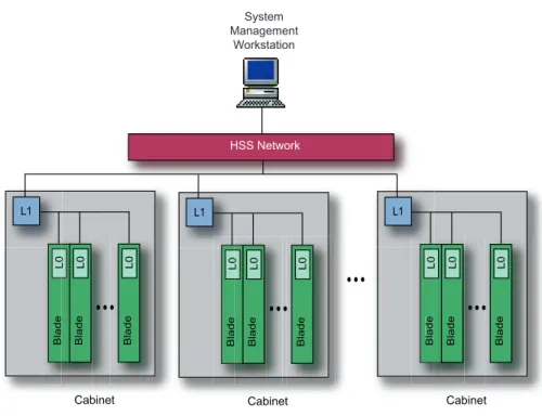
The hardware components of the HSS are the HSS network, the SMW, the blade control processors (L0 controllers), and the cabinet control processors (L1 controllers). HSS hardware monitors compute and service node components,
operating system heartbeats, power supplies, cooling fans, voltage regulators, sensors, microcontrollers, and RAID systems.
Figure 13. HSS Components System Management Workstation HSS Network L1 B la d e L 0 Blade L0 Blade L0 Cabinet L1 Blade L 0 Blade L0 Blade L0 Cabinet L1 Blade L 0 Blade L0 Blade L0 Cabinet
4.1.1 HSS Network
The HSS network consists of Ethernet connections between the SMW and the L1-and L0-microprocessors. The network's function is to provide an efficient means of collecting status from and broadcasting messages to system components. The HSS network is separate from the system interconnection network.
Traffic on the HSS network is normally low, with occasional peaks of activity when major events occur. There is a baseline level of traffic to and from the hardware controllers. All other traffic is driven by events, either those due to hardware or software failures or those initiated by the administrator. The highest level of network traffic occurs during the initial booting of the entire system as console messages from the booting images are transmitted onto the network.
4.1.2 System Management Workstation
The SMW is the administrator's single-point interface for booting, monitoring, and managing system components. The SMW consists of a server and a display device. Multiple administrators can use the SMW locally or remotely over an internal LAN or WAN.
Cray Hardware Supervisory System (HSS) [4]
4.1.3 Hardware Controllers
The L0 and L1 are the controllers that monitor the hardware and software of the components on which they reside.
Every compute blade and service blade has a blade control processor (L0 controller). This processor monitors the following blade components: Opteron status registers, SeaStar status registers, and voltage regulation modules. L0 controllers also monitor board temperatures and the CLE heartbeat.
Each cabinet has a cabinet control processor (L1 controller) that communicates with the L0 controllers and monitors the power supplies and the temperature of the air cooling the blades. Each L1 controller also routes messages between the L0 controllers and the SMW.
4.2 HSS Software
HSS software consists of software monitors; the administrator's HSS interfaces; and event probes, loggers, and handlers. This section describes the software monitors and administrator interfaces. For a description of event probes, loggers, and handlers, see
HSS Actions on page 46.
4.2.1 Software Monitors
The System Environment Data Collection (SEDC) HSS manager monitors the system health and records environmental data (such as temperature) and the status of hardware components (such as power supplies, processors, and fans). SEDC can be set to run at all times (automatic data collection) or only when a client is listening; set theINT:startup_actionoption in the SEDC configuration file to indicate your preference. For additional information, see the Cray XT System Management manual. Resiliency communication agents (RCAs) run on all compute nodes and service nodes. RCAs are the primary communications interface between a node's operating environment and the HSS components external to the node. They monitor software services and the operating system instance on each node.
Through the RCA, the HSS and the system processes running on a node handle event notification, informational messages, information requests, and probing. The RCA also provides a subscription service for processes running on the nodes. This service notifies the current node of events on other nodes that may affect the current node or that require action by the current node or its functions.
Each RCA generates a periodic heartbeat message, enabling HSS to know when an RCA has failed. Failure of an RCA heartbeat is interpreted as a failure of CLE on that node.
RCA daemons running on each node start a system resiliency process called failover manager. If a service fails, the RCA daemon transmits a service-failed message to the HSS.
Failover managers on other nodes subscribe to receive these messages. Each failover manager checks to determine if it is the backup for any failed services that relate to the message and, if it is, directs the RCA daemon on its node to locally restart the failed service.
4.2.2 HSS Administrator Interfaces
The HSS provides a command-line interface,xtcli. For details, see thextcli(8) man page.
If any component of the system detects an error, it sends a message to the SMW. The message is logged and displayed for the administrator. HSS policy decisions determine how the fault is handled. The SMW writes all information it receives from the system to the SMW disk to ensure the information is not lost due to component failures.
4.3 HSS Actions
The HSS manages the startup and shutdown processes and event probing, logging, and handling.
The HSS collects data about the system (event probing and logging) that is then used to determine which components have failed and in what manner. After determining that a component has failed, the HSS initiates certain actions (event handling) in response to detected failures that, if left unattended, could cause worse failures. The HSS also initiates actions to prevent failed components from interfering with the operations of other components.
4.3.1 System Startup and Shutdown
The administrator starts a Cray XT system by powering up the system and booting the software on the service nodes and compute nodes. Booting the system sets up the system interconnection network. A script, set up by the administrator, shuts the system down.
For logical machines, the administrator can boot, run diagnostics, run user
applications, and power down without interfering with other logical machines as long as the HSS is running on the SMW and the machines have separate file systems.
Cray Hardware Supervisory System (HSS) [4]
4.3.2 Event Probing
HSS probes are the primary means of monitoring hardware and software components. Probes hosted on the SMW collect data from probes running on the L0 and L1 controllers and RCA daemons running on compute nodes. In addition to dynamic probing, the HSS provides an offline diagnostic suite that probes all HSS-controlled components.
4.3.3 Event Logging
The event logger preserves data that the administrator uses to determine the reason for reduced system availability. It runs on the SMW and logs all status and event data generated by:
• HSS probes
• Processes communicating through the RCA interface on compute and service nodes
• Other HSS processes running on L0 and L1 controllers
4.3.4 Event Handling
The event handler evaluates messages from HSS probes and determines what to do about them. The HSS is designed to prevent single-point failures of either hardware or system software from interrupting the system. Examples of single-point failures that are handled by the HSS system are:
• Compute node failure. A failing compute node is automatically isolated and shut down and the user job fails; the rest of the system continues running and servicing other applications.
• Power supply failure. Power supplies have an N+1 configuration for each chassis in a cabinet; failure of an individual power supply does not cause an interrupt of a compute node.
In addition, the HSS distributes failure events to those who have subscribed to them over the HSS network so that each component can make a local decision about how to deal with the fault. For example, both the L0 and L1 controllers contain code to react to critical faults without administrator intervention.