*002381-000-70*
002381-000-70
Installation Instructions
Keying Falcon
Interchangeable Cores
Before keying or rekeying an interchangeable core, all pins and springs within the core must be removed. This is accomplished by removal of the brass spring cover from the top of the core. Removal of the spring cover is accomplished through the use of the ejector tool (Part No.1405) from your FALCON Service Kit. Insert the ejector tool into the small hole on the bottom of the core at the back and push up on the stack of pins to dislodge the spring cover. Grip the cover
with a pair of needle nose pliers and remove by peeling it from the dovetail enclosure carefully. Do not attempt to save the spring cover; always use a new one. After the spring cover is off, remove all the pins and springs from the core. Use your ejector tool to be certain all cells are empty. ALL PIN CELLS MUST BE EMPTY BEFORE STARTING TO REKEY.
Bottom Pins: The first pins inserted in the core. They are the pins that contact the key. Never use them as wafers. They are Part Nos. 12636-0 thru -9.
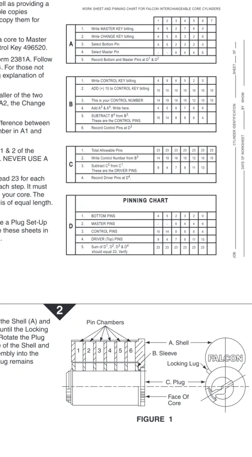
Change Key: The key which will open or operate one core. (It will operate more than one only if they are “keyed alike.”) Control Key: The key which operates only the Sleeve (B), thus
rotating the locking lug, allowing the insertion or removal of a core from its lock.
Control Shear Line:
The area where the Shell (A) and Sleeve (B) meet.
rotatable only by the control key. It is the portion of the core which retains it in the lock.
Master Key: The key which will operate a group of cylinders, each of which is operated by it own individual change key. Operating Shear Line:
The area where the Sleeve (B) and the Plug (C) meet. Where all pins must be level when the change key or master key is inserted in order to operate the core. (See Figure #2).
Pin Cells: The holes within the Shell (Figure 1a), Sleeve (B)
Definitions
Preparation
2
Before proceeding to pin up the core, FALCON Form 2381A should be completed. When completed, the form shows exactly which pins to put into the core as well as providing a permanent record of your work. Reproducible copies accompany these instructions. Feel free to copy them for your use.
Our sample work sheet will be used to pin a core to Master Key 452760, Change Key 458326 and Control Key 496520. Very little instruction is necessary to use Form 2381A. Follow directions as given from Section A1 thru C4. For those not experienced in Master Keying, the following explanation of A3 and A4 is offered.
At A3, the bottom pin will always be the smaller of the two numbers between A1, the Master Key and A2, the Change Key. See our sample form.
At A4, the Master Pin number will be the difference between the bottom pin number and the highest number in A1 and A2, whichever is greatest.
Where no master pin is required (Columns 1 & 2 of the example form), place a dash (—) as shown. NEVER USE A 0 (zero) TO INDICATE NO MASTER PIN.
Upon completion of Section D, D5 should read 23 for each column. If it does not, go back and check each step. It must total 23 before you can use this chart to pin your core. The total 23 assures us that every stack of pins is of equal length. This is a must.
Upon completion of Section D you now have a Plug Set-Up chart from which you can pin your core. File these sheets in a 3-ring notebook for a complete job record.
WORK SHEET AND PINNING CHART FOR FALCON INTERCHANGEABLE CORE CYLINDERS 1 2 3 4 5 6 7 4 5 2 7 6 0 4 5 8 3 2 6 4 5 2 3 2 0 4 9 6 5 2 0 4 5 8 7 6 6 10 14 8 8 6 4 - - 6 4 4 6 A 10 10 10 10 10 10 10 14 19 16 15 12 10 10 14 19 16 15 12 10 10 9 4 7 8 11 13 4 5 2 3 2 0 - - 6 4 4 6 10 14 8 8 6 4 9 4 7 8 11 13 23 23 23 23 23 23 B 23 23 23 23 23 23 23 C D PINNING CHART CYLINDER IDENTIFICA TION DA TE OF WORKSHEET BY WHOM: SHEET OF JOB:
1. Write MASTER KEY bitting. 2. Write CHANGE KEY bitting. 3. Select Bottom Pin 4. Select Master Pin
5. Record Bottom and Master Pins at D1 & D2
1. Write CONTROL KEY bitting. 2. ADD (+) 10 to CONTROL KEY bitting
4. Add A3 & A4; Write here.
5. SUBTRACT B4 from B3.
These are the CONTROL PINS. 6. Record Control Pins at D3
1. Total Allowable Pins
3. Subtract C2 from C1.
These are the DRIVER PINS. 2. Write Control Number from B3
4. Record Driver Pins at D4.
1. BOTTOM PINS
5. Sum of D1, D2, D3 & D4
should equal 23. Verify 2. MASTER PINS 3. CONTROL PINS 4. DRIVER (Top) PINS 3. This is your CONTROL NUMBER
FIGURE 1
A. Shell B. Sleeve C. Plug Face Of Core Pin Chambers 1 2 3 4 5 6 Locking LugBefore loading any pins into the core, align the Shell (A) and Sleeve (B) holes by rotating the Sleeve (B) until the Locking Lug is projecting out of the core assembly. Rotate the Plug (C) so the holes DO NOT line up with those of the Shell and Sleeve. (See Figure 1). Insert the core assembly into the pinning block, making certain the Locking Lug remains projecting.
Tapping Plate (No. 1415) Dovetail Pinning
FIGURE 2
Stack-up Equal Locking Lug Operating Shear Line Control Shear Line 9 10 4 4 14 5 7 8 6 2 8 8 4 3 11 6 4 2 13 4 6 0Now load your pins into the core through the cell holes in the top of the Shell. Always load the core from back to front. The #1 cell hole is at the back of the Plug. The #1 position on the Key is at the tip.
Using Section D (Pinning Chart) of your completed Form 2381A as your guide, pin up your core. Always load them directly from the Pin Kit into the cell hole to prevent possible mix-up by selecting them and laying them out in your pin tray. Completely load one cell hole at a time.
When all of the pins have been loaded into the core, check to see that they are all at the same level, as shown in Figure 2. If any stack is higher or lower than the others unload that stack only, check it and repin it. Using a wrong pin or wafer can cause the stack to be too high or low.
Once the core is loaded properly, turn the Plug back to its neutral position, keyway straight up and down. This will allow all pins to drop into the plug. With your Tamping Tool (Part No. 1405), be sure all pins are seated properly in the Plug. Now place a spring on top of each stack of pins. As shown in Figure 3, place a Spring Cover of the proper length over the Springs.
Place your Tapping Plate (Part No. 1415) over the Spring Cover (rib side down) and strike it firmly with a small hammer to wedge it properly into the dovetail slot. Check to see that it is firmly seated and cannot be moved. (Figure 4).
Last but not least, check all of your keys to see that they operate the core properly. One last suggestion, just prior to loading the Springs into the cells, add just a drop of DRY powdered graphite on the top of each stack of pins.
3
4
FIGURE 3
Spring Cover (12630-1) Spring (12637) Core Assembly Sleeve4
USE THE FOLLOWING PART NUMBERS:
No. 1404 Keying Kit, Complete (Wood Case) No. 1405 Ejector Tool
No. 1407 Mortise Cylinder Installation Wrench No. 1411 Pinning Block Set
No. 1414 Pinning Block No. 1415 Tapping Plate No. 12612 Key Gauge No. 12630-1 Spring Cover, 6 Pin No. 12630-2 Spring Cover, 7 Pin No. 12635 Wafer, #2 through #19 No. 12636 Bottom Pin, #0 through #9 No. 12637 Tumbler Springs
No. 12646A 6 Pin Core, not pinned. No. 12647A 7 Pin Core, not pinned. No. 2381 Keying Instructions
No. 1411 PINNING BLOCK SET CONSISTS OF:
No. 1414 Block
No. 1415 Plate
No. 1405 Ejector and Tamping
8.500
11.000 FRONT
Additional Notes: Revision History Revision Description:
D > Revised artwork
1. None A B C D E F
5598 0790 6683 17.000
11.000
BEGINNING SHEET FOLDED SHEET