Paramètres de calcul géotechnique. Magnan (ed.) 2002, Presses de l’ENPC/LCPC, Paris
PARAMETER SELECTION FOR SUBMARINE CABLE BURIAL ASSESSMENT
CHOIX DES PARAMÈTRES POUR l’ENFOUISSEMENT DES CÂBLES SOUS-MARINS
H.J. Tuenter1
1 Fugro, Leidschendam, The Netherlands
ABSTRACT - Parameter value selection for submarine cable burial assessment focuses on soil
identification and characterisation, using a combination of standard and novel geophysical techniques, sampling and in-situ Cone Penetration Testing. This integrated approach is the key to obtaining representative parameter values continuously along the entire route. Results of analyses compare favourably with observed cable installation data.
RÉSUMÉ – Le choix des paramètres pour estimer la possibilité d’enfouir les câbles sous-marins
s’appuie sur l’identification et la caractérisation des sols en combinant des techniques géophysiques classiques et innovantes, des prélèvements et des essais au pénétromètre statique. Cette approche intégrée permet d’obtenir des paramètres de façon continue sur l’ensemble du tracé. Les résultats obtenus reproduisent bien les observations réalisées lors de l’installation de câbles.
1. Introduction
Over the past few years there has been a rapidly growing demand for data transmission. Telecommunication companies have been trying to keep pace with this increasing demand by expanding their capacity, resulting in the installation and commissioning of thousands of kilometres of fibre-optic telecommunication cables.
In order to ensure data transmission continuity, offshore telecom cables require protection against natural hazards, fishing activities and ship anchors. Several options are available to prevent damage to the cable, the ones most often applied being: avoid known hazards; bury the telecom cable into the seabed; and increase the cable resistance against impact (armouring).
A phased approach applies to obtaining the information required for selecting the appropriate means of protection:
• desk top study for initial route selection and preliminary cable hazard identification;
• route survey for route optimisation, hazard identification and preliminary selection of cable protection;
• burial assessment survey along selected route sections.
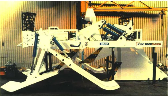
The purpose of the burial assessment survey is to ensure the future cable is well protected by either burial or increased armouring. Cable burial is commonly achieved by means of a dedicated cable plough, an essentially passive tool creating a narrow trench while simultaneously installing the telecom cable. Such ploughs are operated from purpose-built cable installation vessels and typically weigh between eleven and thirty metric tonnes. Plough performance with regard to burial depth considers limit equilibrium soil-plough interaction. The ground behaviour model considers undrained behaviour for fine grained soils and drained behaviour for coarse grained soils. Parameters required primarily pertain to soil stratification, the angle of internal friction and undrained shear strength, depending on soil type.
The difficulties associated with any assessment of the feasible burial depth are considerable. The route length along which parameter values are required often literally amount to hundreds of kilometres. Parameter values are required continuously, both along the entire route length as well as in depth. However, most geotechnical investigation methods only provide data at isolated locations. Furthermore, data are required for the upper 1 to 2 metres of seabed, where traditional geophysical methods have not been particularly successful. To further complicate matters, the viability and profitability of submarine telecom system installation and operation often depend on
laboratory test programme. It also implies that route selection is often done concurrently with field data acquisition along this very route, effectively making change the only constant.
In response to those challenges and recognising that no single discipline alone can provide all the answers, the cable industry has embraced the concept of the “integrated study”, a term denoting the multi-disciplinary approach to ground mass modelling. This approach focuses on identifying the spatial ground structure and characterising ground behaviour by combining the specialist tools and knowledge of geology, geophysics and geotechnics to come up with a single answer to the main question: can I bury my cable into the seabed?
Figure 1. Submarine cable plough
2. Data Integration
2.1. Data Sources 2.1.1. Geophysical data
Ground mass modelling for cable burial assessment uses a range of geophysical and geotechnical techniques. Geophysical systems commonly employed include:
• Single and multi-beam echosounder;
• Side Scan Sonar;
• 2D high-resolution seismic reflection.
Echo sounder data provide information regarding seabed bathymetry. Side Scan Sonar data provide detailed data regarding seabed features, and assist in identifying seabed structures and obstructions. Seismic reflection data assist in identifying soil boundaries and layering, both laterally and with depth. Geophysical data acquisition is commonly complemented with gravity or dredge sampling to assist data interpretation.
Over the last few years, the additional use of novel high-resolution sled-based geophysical systems has assisted in obtaining more complete and better quality data. In particular, seismic refraction and electrical resistivity systems have been commercially used. In comparison to traditional 2D geophysical systems, these excel in obtaining data from the upper 2 to 3 metres of seabed. This coincides with the approximate depth to which telecom cables are buried into the seabed. Puech (1999) and Puech and Kolk (2000) provide further details on high-resolution sled-based geophysical systems used for cable burial assessment.
2.1.2. Geotechnical data
Geotechnical data acquisition usually follows the geophysical data acquisition stage. Preliminary geophysical data are used to select optimum locations for geotechnical testing. Geotechnical investigation methods commonly used include:
• electrical Piëzo-Cone Penetration Testing, typically once per 1 to 4 km;
• soil sampling, typically once per 10 km;
• strength index testing (pocket penetrometer and hand-held vane).
Piëzo-Cone Penetration Test results ultimately provide data regarding the depth of soil boundaries, the in-situ density condition and/or soil consistency. Soil samples are used for soil classification purposes and to verify CPT based soil classification. Kolk and Mannaerts (1999) provide further details on coring, laboratory testing and CPT performance and interpretation for cable burial assessment purposes. Laboratory testing on selected soil samples, beyond the level of strength index testing, is rare. The design and installation of submarine cable plants by definition is fast-tracked, and extensive laboratory testing programmes are too time-consuming. Figure 2. summarises data sources available and their relation to ground mass modelling.
Figure 2. Summary of data sources for ground mass modelling
2.2. Discrepancy sources
Ideally, after processing and interpretation all data sets should tie in at similar XYZ locations. Unfortunately, often different systems come up with different answers. Discrepancies pertain to both the location of soil strata boundaries as well as to soil characteristics.
Discrepancies between different data sets originate from various sources. These include:
• system accuracy and resolution (horizontal and vertical);
• differences in measurands;
• XYZ control;
• calibration and processing errors;
• sample disturbance; 1500-1600m/s
1700-1800m/s
1800-2000m/s
>2000m/s Side Scan Sonar / Echo sounder
Piezo-Cone Penetration Test
Sampling
2D Reflection
2D Refraction
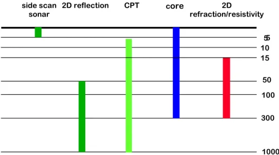
Differences in accuracy and resolution between the various systems used during a burial assessment survey may be a source of conflicting information. This applies in particular to vertical resolution (Figure 3). Each and every data acquisition system has a different vertical resolution, a depth range within which data are clearly identified. This range differs from one system to another. Thus, data extrapolated outside their respective depth ranges may be contradictory. This could for instance be the case when Cone Penetration Test results are integrated with Side Scan Sonar data, which reflect the upper few centimetres of seabed. The top sediment interpreted from sonar imagery does not necessarily correspond to the top sediment interpreted from CPT records, as the influence zone affecting CPT measurements exceeds Side Scan Sonar penetration depth.
Figure 3. Indicative depth range for reliable data acquisition
Differences in measurands pertain to the fact that every system measures a different soil property, on the basis of which ground mass structure and lithology are interpreted. For instance, reflection seismics measures the two way travel time and acoustic impedance, whereas resistivity based methods rely on differences in electrical conductivity of the ground mass. As a result of these differences in measurands, apparent unit changes and additional features detected by one data acquisition system do not necessarily show up in the data of other systems. Furthermore, apparent unit changes, such as a change in acoustic impedance or soil resistivity, do not necessarily reflect a significant change in geotechnical engineering properties.
Whereas above sources of potential inconsistency between various data sets are inevitable and associated with system design, errors may be introduced for various reasons. XYZ control of towed and/or remotely operated systems is limited and subject to uncertainties. The overall uncertainty of the actual location of the data acquisition system depends on positioning equipment used and on the water depth. In general it holds that the uncertainty in XYZ positioning increases with water depth.
Calibration and processing errors are a potential source of error for any data acquisition system. The possibility of errors being made can be reduced by stringent quality assurance systems, but their non-occurrence cannot be guaranteed.
Errors induced by sample disturbance in principle only pertain to core data. However, in practice interpretation of most remote sensing data, including seismic- and resistivity-based methods, partially relies on sample information. An infamous example of this is soil re-sedimentation in a core barrel, typically resulting in a thin top layer consisting of clay overlying coarser material. Interpretation of Side Scan Sonar data with respect to bottom sediment relies on associating various tones of grey, representing the scatter of emitted energy on the seafloor, with observed surface sediments. Hence the presence of a re-sedimented clay top layer at the core top may lead to large areas being misinterpreted as clay. The fact that complementary sampling is only performed approximately once every ten kilometres only adds to the potential impact of such errors. 5 10 50 100 300 1000 side scan sonar 2D reflection CPT core 2D refraction/resistivity 15 5 D e p th [c m ] ( n o t t o s c a le )
Last but not least, different disciplines often adhere to different soil classification schemes to describe discipline-specific features. For instance, in geophysics soft sediment tends to be labelled clay or mud, based upon a relatively low pressure wave velocity or low energy scatter. Geotechnically speaking though, such sediment could perhaps well be described as silt or peat.
Based upon above review of potential sources of discrepancy, it follows that ground mass modelling based upon an integrated study can only be performed satisfactory while having a sound background in the disciplines involved. If well performed the resulting ground model values more than the sum of the individual components.
3. Geotechnical parameter selection
3.1. Methodology
Cable burial analysis is conceptually similar to the geotechnical design of a shallow foundation. The vertical load exerted by the plough share, the in-ground trenching blade, on the ground must equal the ground bearing capacity plus the soil friction on the sides of the plough share. Full penetration, i.e. plough share penetration to the required depth, is achieved only if the vertical compressive load exceeds the ground bearing pressure to at least the required cable burial depth. Plasman et al. (2001) provide further details on burial assessment methods.
The following conditions apply for cable burial assessment:
• low confining stress levels, on account of the shallow cable installation depth;
• large strains in order to create the required trench;
• high rate of loading.
Strength parameters for burial assessment in soils are the angle of internal friction and undrained shear strength, depending on soil type. The assessment of in-situ strength parameters is based upon Cone Penetration Test results. Values are subsequently interpolated on the basis of the previously derived ground model.
A wide range of methods is available for deriving the friction angle of granular soils. Lunne et al. (1997) present a comprehensive review. Derived values for friction angle are generally high on account of the very low stress levels and the high loading rate. The reference method for derivation of the peak friction angle is drained triaxial compression testing. The effective cohesion intercept is commonly ignored, as a reliable estimate of this parameter value is beyond the burial assessment survey. Furthermore, the contribution of the cohesion intercept to the strength of granular soils is relatively small.
Derivation of parameter values for the undrained shear strength is also based upon Cone Penetration Test results, and indicative handheld torvane readings. The cone resistance is corrected for cone geometry related pore pressure effects. Derivation of undrained shear strength includes a correction for overburden stress effects according to Aas et al. (1986). The reference undrained shear strength is the average value of triaxial compression, direct simple shear and triaxial extension.
It is recognised that with the methods and procedures outlined above the soil strength can only be approximated. Numerous effects influencing soil strength have been ignored, due to the small amount of geotechnical soil strength data. What is the value of such approximate assessments? 3.2. Results of cable burial assessment
The value of the procedures and methods outlined in previous paragraphs can be assessed when comparing burial predictions with actual cable installation data. Data are taken from a North Sea site, where the actual cable was installed in 1998. During the installation campaign severe difficulties were encountered while trying to install the cable in dense sand.
The strength of the sand has been assessed on the basis of Cone Penetration Test data according to the procedures described earlier. Installation data pertain to locations situated 10 to 400 metres from the actual CPT location. As such both the calculation procedure and the associated parameter value determination, as well as the ability to interpolate data are
Figure 4. Predicted versus measured burial depth
Figure 4 summarises results. The angle of internal friction of the sand below the plough share tip (estimated from CPT data) is plotted against the horizontal axis. The vertical axis denotes the burial depth. The full line gives the theoretical prediction for a given plough with a maximum depth capability of 1.2 m. A fair agreement exists between predicted and observed data, with an average error of approximately 0.2 metres.
Cable installation in normally and overconsolidated clays is usually successful due to insufficient bearing capacity of the soil. Bearing capacity based predictions for cohesive soils confirm that cable burial can be achieved to the required depth.
4. Conclusions
Several specific challenges apply to the geotechnical analysis of cable burial in the seabed. These predominantly originate from the requirement for accurate parameter values while lacking sufficient geotechnical engineering data. How to overcome these?
• With respect cable burial assessment, the overall accuracy of geotechnical engineering both depends on the accuracy of parameter value determination as well as the ability to accurately model the ground mass along the cable route.
• The integrated study approach has proven a viable way to model the ground mass. Numerous pitfalls exist, but when performed correctly the quality of the final ground model exceeds the sum of its components.
• Geotechnical parameter values are derived at isolated CPT locations. Parameter values are subsequently interpolated on the basis of the ground mass model.
• Despite the approximate nature of parameter value selection, results of actual cable installation data compare favourably with burial predictions. The presented installation data are considered a check on the accuracy of ground mass modelling as well as model parameter value selection.
On the basis of the results presented herein it is argued that “more advanced” does not necessarily mean “better”. Given the challenges and limitations of cable burial assessment, it is the author’s opinion that the current limitations in the accuracy of parameter determination are acceptable. Rather, it is envisaged that an increase in the accuracy of geotechnical engineering predictions would primarily result from further improvements in ground mass modelling.
0 0.5 1 1.5
10 20 30 40 50 60
Peak secant friction angle φφφφ' [0]
B u ri a l d e p th [ m ] predicted observed
5. References
Kolk H.J., Mannaerts H. (1999) Advances in cable burial assessment. Proceedings, International
Conference on Submarine Networks, London.
Lunne T., Robertson P.K., Powell J.J.M. (1997) Cone penetration testing in geotechnical practice, Blackie Academic & Professional, London.
Plasman S., Kolk H.J., Tuenter H.J., Puech A. (2001) Developments in data acquisition and analysis for cable burial assessment. Proceedings, 4th International Convention on Undersea Communications ‘SubOptic 2001’.
Puech A. (1999) GAMBAS: A high resolution seismic refraction tool for continuous cable burial assessment. Proceedings, IBC 2nd Annual Conference on Submarine Communications, Cannes. Puech A., Kolk H.J. (2000) Recent developments in cable BAS data acquisition and analysis. ICPC