Using Spec Explorer for Automatic Checking of Constraints in Software
Controlled Systems
Salam AL-EMARI1, Izzat Mahmoud ALSMADI2 1
Computerscience department, IT faculty, Yarmouk University, Irbid, Jordan 2
Computer information system department, IT faculty,Yarmouk University, Irbid, Jordan [email protected], [email protected]
In software engineering, several formal models and tools are proposed for defining system requirements and constraints formally. Such formal definitions can help in the automatic checking and verification for them. It can also help in the automatic test case generation, execution and verification. In this paper, we will demonstrate and evaluate the usage of Spec Explorer from Microsoft for defining and checking examples of software controlled system such as cruise control. Such formal requirements can be eventually embedded in the developed system or can help in exposing important elements to test in the testing stage or through the usage of the application.
Keywords: Model-Based Testing, Spec Explorer, FSM Models, Software Controlled Systems
Introduction
Software testing is the process of executing software to determine if it works correctly and according to the specified requirements. Software testing can be manual or automatic. These days software applications are increasing in complexity and size which make manual testing not efficient because it takes a significant time and effort of the project resources. Automation is the integration of testing tools into the test environment in such a manner that the test execution, logging, and comparison of results are done with little human intervention. A testing tool is a software application which helps automate the testing process. Although automatic testing reduces time and effort however, not everything in the software can be tested automatically. There are many reasons why some parts of the software can’t or can hardly be tested automatically [1] [2]. Model-Based Testing (MBT) “is an evolving technique for generating test cases automatically from a behavioral model of a system under test” [17]. By applying MBT, defects can be found earlier in the development process compared to the use of manual testing practices. The MBT includes three main stages, first test case generation from models according to a given test selection criterion, second test execution, and third the test evaluation [1] [3]. The second
and third stages are often combined leading to the so called on-the-fly test case generation methods. If main stages work separately it is called batch test case derivation. MBT has four approaches for automatic testing; a random testing approach, goal oriented approach, intelligent approach and path oriented approach [5].
The growing use of Graphical User Interfaces (GUIs) in software led to the focus on GUI testing. Until now development coverage criteria for GUI’s have not been addressed [6]. Testing through GUI is more complex. We will elaborate in the next section some of the challenges of using GUI model based testing.
MBT is a testing technique where test cases are generated from a model of the system. There are several MBT tools that can automate the generation of test cases from a behavioral model, including test oracles that can determine whether the system under test behaves correctly at the execution of the test cases. In this paper we will elaborate in one of those tools; Spec explorer tool developed at Microsoft Research.
The rest of the paper is organized as the following: Section II summarizes some of the literature review, discusses MBT, GUI and FSM models. Section III describes goals and approaches and discusses model-based testing tool Spec Explorer. A case study is
1
presented in the section. Section IV includes conclusion and future work.
2 Literature Review
Testing is an essential part of software project development. With the increase of software complexity, the challenges of testing are increasing. Testing occurs in all states of the software development process. The testing phases try to answer six questions. These questions provide very simple and intuitive characterization schema of software testing activities. WHY: why is it that we make the observations? This question answers test objectives and reasons that led to the need for testing. HOW: which sample or parts do we observe, and how do we choose those parts? This is the problem of test selection. Methods of implementing the testing process and selecting which approach to follow are not always a straightforward decision to make. HOW MUCH: how large is the sample and how much to test? This question can be better answered after knowing the answers for the previous questions. WHAT: what is it that we execute?
This question concerns system under test, execution testing on system as a whole, or focusing only on a subset or a part of it (i.e. unit test, component/ subsystem test, integration test). WHERE: where do we perform the observation? This question can be accomplished in a simulated environment or in the target final context or application. This question assumes the highest relevancy when it comes to testing embedded systems. WHEN: when is it in the product lifecycle that we perform the observations? The stage of the software development can have a significant impact on what we test and how we perform testing activities [14].
Manual testing is usually error-prone, time and resources’ consuming. MBT approach is to model the desired behavior of the implementation under test (IUT). The objective of MBT is to be able to automatically generate high-quality test suites from models thus implementing automated test execution. Features provided
by MBT, allow test automation and allow for automatic generation of a large number of test cases from models. MBT is a good approach to improve quality and effectiveness of testing and also reduce cost of testing. MBT depends on formal methods and verification techniques when describing the characteristics of the system or problem domain [9].
Automatic testing effort is divided into three major parts: test case generation, execution and test evaluation. A test case is represented by three major attributes: [I, S, O]. (I) is the input data to the test case, (S) is the object or system state or any pre conditions required to start executing the test case, and (O) is the expected output data (e.g. post conditions). Automatic test case generation requires formal or semi-formal specifications to select test cases to detect faults in code implementation.
MBT is technique for automatic generation testing using models. A model is simplified depiction behavior software. There are several model based approaches proposed in software design. Selecting one model depends on software behavior or structure description, on the test-generation algorithm (criteria) and on tools that provide supporting infrastructure for the tests. The selection of the MBT approach for software product it’s hard, this case lead to the testers have knowledge regarding to MBT approach. Some models describe behavior source code structure such as control flow and data flow. Some models describe external so called black-box behavior such as state machine [7] [8].
Today, many software products provide a Graphic user interface (GUI). A typical GUI gives many degrees of freedom to an end-user, leading to an enormous input event interaction space that needs to be tested. It should be model to ensure correct operation done for GUI. GUI testing can be used to confirm the validity of a sequence of event on one or more GUI widgets. In GUI testing, testing interacts only through interfaces. Current GUI testing techniques used in practice are incomplete, ad hoc, and partially
automatic. Some GUI models for testing are expensive to create and have limited applicability. Models and techniques have been developed to address the automation of specific aspects of the GUI testing process is not developed for a full GUI [12]. There are many graph models to model the user interface based on specific aspects. We will describe two graph models, event-flow graph and control flow graph.
Event-flow graph (EFG) is a GUI model
which can be used for GUI testing. It represents events and event interactions and represents all possible sequences of events that can be executed on the GUI. Event-flow model contains from two important parts to present user profiles and check for run-time consistency of the GUI. The first part encodes each event in terms of preconditions, such as the changes to the state after the event has executed. The second part represents all possible sequences of events that can be executed on the GUI as a set of directed graphs. Each event represent how modify on state. State of each widget (e.g. buttons, textbox, label, menu) and container (e.g. panel, group box, frame) all widgets and containers will be referred to as GUI object. Each object represent by properties such as location and background so event from GUI
is change the state of objects. The events E = {e1, e2, …, en} implement by function can change GUI from one state to another which this states may be infinitely of the GUI. An EFG model is represented by < V, E > each vertex represents an event (e.g. click on edit) and each edge from vertex X to vertex Y explains how to reach Y from X directly [10].
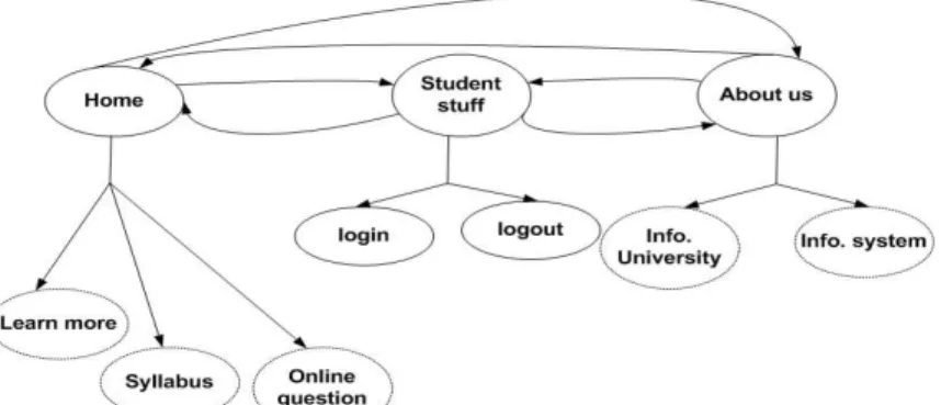
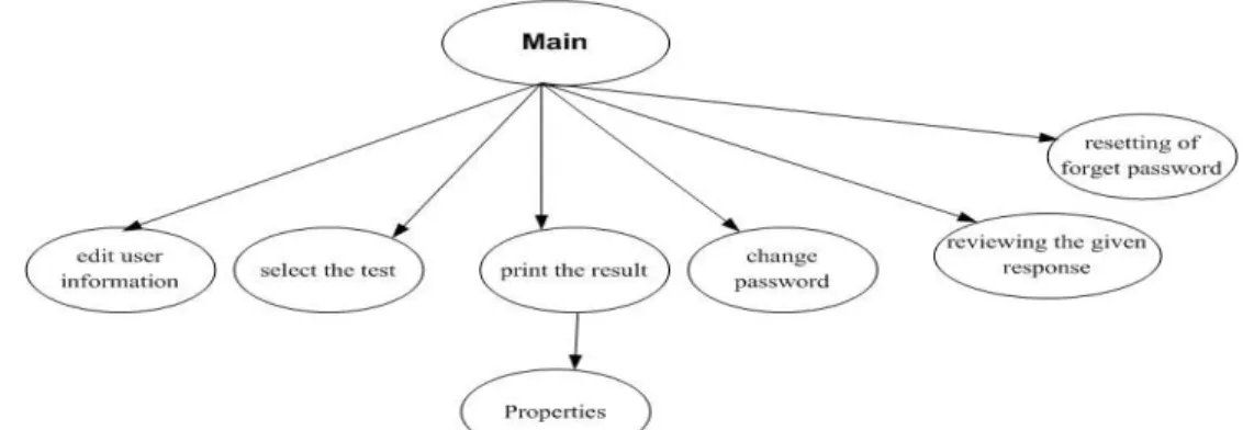
In EFG, the total number of all possible event sequences in any complex GUI can be very large. GUI can be decomposed into several GUI sub components each one represents a unit of test. The interactions among component are captured by a representation called the integration tree [6]. In an online-exam system (as an online-example of an EFG), the online-exam system has many components for different purposes. There are components for user interactions: main, edit user information, select the test, print the results, change password, reviewing the given response, resetting of forget password) [15]. In Figure 1 we showed part of event-flow graph, event sequence for GUI very large impractical to test. The component which is used more frequently is deeper in tree integration. Figure 2 shows tree integration for Figure 1.
Fig. 2. A tree integration for part of an Online-Exam system
Control flow Graph (CFG). CFG model is
drawn to understand the complexity in software in terms of possible decisions and branches. CFG is a direct graph that contains: nodes, edges, entry node and exit node where entry and exit nodes should be different and distinguished. In a simple example for a multiple choice automatic grading program where a user is prompted by a question and choices, a correct choice increment the user grade and an incorrect answer may deduct from their grade (which is not usually the case). Figure 3 shows the CFG for the following pseudo code.
1. char choice = null; 2. bool end = false; 3. While (end != true) {
4. If (event_click_OnFinishExame() = = true) 5. end = true; 6. Select choice ; 7. If ( compare_choices( choice) = = true) 8. Add_to_score(); 9. else 10.deduct_from_score(); } 11.print_Result();
CFG encodes all possible execution paths in a program. EFG represent all possible sequence of events that can be execute on GUI. There are lacks on current techniques, long event sequences, lack a systematic exploration of the impact of context-aware GUI interaction testing on fault detection and lack test adequacy criteria [12].
Fig. 3. A simple control flow graph
Generation for a question answering system
This research focuses on the important model used in object-oriented software testing is
FSM (Finite State machines) [1]. This model depends on scenario a tester applies an input and then appraises the result then select another input depends on pervious result. State machines (directed graphs) are ideal models for describing sequences of inputs, complex software combined from large state. FSM also known as finite automata is one that has a limited or finite number of possible states. FSM can be used both as a development tool for approaching and solving problems and as a formal way of describing the solution for later developers and system maintainers. FSM general form
(I, S, T, F, L), where (I) is inputs of the system, (S) is set of all states of the system, (T) is transition occurs by function, (F) is final state, (L) is the state into which the software is launched. One state at one time, FSM has two main state; initial state to start and final state the end FSM. Finite state models are an obvious fit with software testing where testers deal with the chore of constructing input sequences to supply as test data [8].
Usually in FSM program the state represent some aspects of the control follow program, for example the state in GUI may be the current screen on display. FSM has some limitations, First state explosion where the number of sates in FSM grows exponentially. The second limit test case explosion, the coverage criteria in FSM states and transition produces a huge number of case tests. The third limit black-box testing of concurrent programs is the presence of non-determinism in the expected behavior of the program. Final limit skills for define FMS model and tool work with state and test case
3 Goals and Approaches
In order to evaluate Spec explorer tool in software testing. Spec Explorer is first described in a demo using Cruise control system as a case study. Spec explorer will be used to describe the system and show possible areas to verify.
Microsoft’s Spec Explorer
Spec explorer is a model-based testing tool, it extends Microsoft Visual studio creating by software Engineering group in Microsoft research for modeling software behavior, has been used since 2003. Model program defines the state variables and rules written in C#.net or any other language in .net and abstract state machine which write in Cords
scripts (a set of coordination) for configuring model exploration and testing as well as composing scenarios. We discuses spec explorer 2010 last version for Microsoft, it analysis models graphically, checking the validate models and generating test cases from models [16] [17] [19].
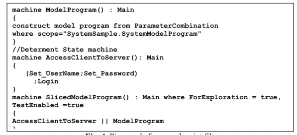
Other systems have user class for allow specify user register in system, user make two primary operation login and logout. Class user has attributes (userID, userName, password, and name) and methods (getUserID, setUserID, getUserName, setUserName, getPassword, setPassword, getName, setName, login, logout). We using spec explore for test operation login without care for implementation. The user must have correct username and password to even be able to enter the system [15]. Scenario login: the user enters username and password then login then the system verify login. We assume tow conditions for scenario login, first condition password length grate than 5 characters and second condition both username and password must be correct. A login scenario login is written in cord script is binding through rules which there are in another file (model program file) in .net language. “machine” is keyword in cord script, it use to define scenario to do test generation through exploration process. Cord script use process algebra to express the scenario such as
Union operator (|), sequence operator (;), Synchronized Parallel Composition operator (||)…etc [19]. Figure 4 see “machine AccessClintToServer” display scenarios. Machine “ModelPrograme” determent path model file which contain rules and actions for test. Machine “SliceModelPrograme”
invoke machine “AccessClintToServer” to work parallelwith machine ModelPrograme.
Fig. 4. Piece code from cord script file Figure 5 present the result for Figure 4 by
FSM model. The result has 19 transitions and 15 states where (S0) start state of gray color, state (S16, S18) wrong state of red color and states ( S27, S28) final state of green color.
Table 1 explains briefly the result. With simple scenario and simple rule the spec explorer display all possible paths as FSM model.
Fig. 5. An FSM model visualized by Spec Explorer
Table 1. Explain each transition between two states for result in Figure 5
Si Sj Is correct operation
S0 S4 yes user name register in system S4 S18 no password is null character
S4 S17 yes password is correct
S17 S27 yes Login is true
S4 S16 no password is wrong
S0 S5 no user name with null value
S5 S21 no password is null value
S21 S28 no Login is false
S5 S20 yes Password is correct
S20 S28 no Login is false
S5 S19 no Password is wrong
S19 S28 no Login is false
S0 S6 yes Set user name isn’t register in system machine ModelProgram() : Main
{
construct model program from ParameterCombination where scope="SystemSample.SystemModelProgram" }
//Determent State machine
machine AccessClientToServer(): Main {
(Set_UserName;Set_Password) ;Login
}
machine SlicedModelProgram() : Main where ForExploration = true, TestEnabled =true
{
AccessClientToServer || ModelProgram }
S6 S24 no Password is null value
S24 S28 no Login is false
S6 S23 yes Password is correct
S23 S28 no Login is false
S6 S22 no Password is wrong
S22 S28 no Login is false
A case study
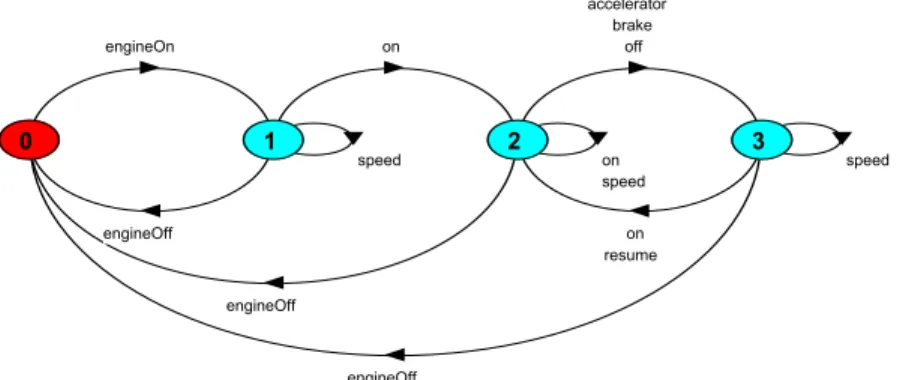
In this section, we investigate the benefits of using Spec explorer in software testing. Using Cruise Control System (CCS), we want to explore the behavior of the system to see if we can discover anomalous behavior in spec explorer tool. CCS system keeping an aromatic traveling at a certain speed, it recode the current speed and maintains automatically. CCS controller three buttons
(on, off, resume) if state engine is off then CCS is disable. When state engine is on CCS have new speed setting, engine is running and CCS on the system start record speed if press (accelerator, off or break) CCS is disable but it return to previous speed setting if press resume button, Figure 6 displays CCS in LTS (Labeled Transition System) [20]. engineOn engineOff on speed engineOff on off brake accelerator speed engineOff on resume speed 0 1 2 3
Fig. 6. Cruise Control system in LTS [20]
We will use spec explorer tool to test cruise control system specifications. To get results from spec explorer in FSM model we have created a project which contains the model.
The model consists of two files linked together, the first file
CruiseModelProgram.cs, C# file to define the model program, condition and configuration parameters which work with second file (see appendix B). The second file is Config.cord, cord script file to define machine and explorer it (see Figure 7 and appendix A).
Fig. 7. Defining a machine in cord script
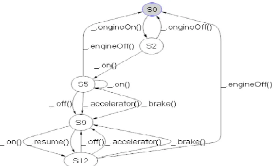
Figure 8 displays results in Spec explorer when explorer machine Cruise_Controller()
through apply appendix (A and B). Table 2 explains briefly the result in Figure 8. In each state we can detriment state control and state speed. State control is a passive entity, it reacts to events. It as a monitor may be (Inactive, Active, Cruising or Standby). State speed an active entity, when enabled, a new thread is created which periodically obtains car speed and sets the throttle may be
machin machin_name() : name_config
{
// write scenario methods by use process algebra between methods }
(Disable, Enable). Figure 9 display results through apply appendix (A and C) which
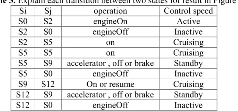
only take state control. Table 3 explains briefly the results in Figure 9.
Fig. 8. Cruise Control system in Spec explorer
Fig. 9. Cruise Control system in Spec explorer
Table 2. Explain each transition between two states for result in Figure 9
Si Sj operation Control state Speed state
S0 S2 engineOn Active Disable
S2 S4 on Cruising Enable
S4 S0 engineOff Inactive Disable
S4 S9 accelerator , off or brake Standby Disable
S9 S12 on or resume Cruising Enable
Table 3. Explain each transition between two states for result in Figure 9 Si Sj operation Control speed
S0 S2 engineOn Active
S2 S0 engineOff Inactive
S2 S5 on Cruising
S5 S5 on Cruising
S5 S9 accelerator , off or brake Standby
S5 S0 engineOff Inactive
S9 S12 On or resume Cruising S12 S9 accelerator , off or brake Standby
S12 S0 engineOff Inactive
4 Conclusion
Model-based testing (MBT) is usually used in testing for the automatic generation of test cases (i.e. based on the defined model). This research used Spec Explorer tool to formally define system requirements and show how test cases can be automatically generated from this model. As a sequential system with several states, and constraints, cruise control system case showed that once requirements are fully collected and correctly defined, a formal model can be very effective in automatically generating test cases to evaluate an application. Formal models can be also used to create the design and possibly find weakness in the design before reaching the implementation and testing stage where fixing such problems can be expensive in terms of time and resources.
References
[1] S.K. Swain, S.K. Pani, D.P. Mohapatra, “Model based object-oriented software testing,” ACM, 2010.
[2] S. Koirala, S. Sheikh, Software Testing Interview Questions, Infinity Science Press LLC, 2008.
[3] M. Mlynarski, B. Güldali, M. Späth, G. Engels, “From Design Models to Test Models by Means of Test Ideas,” ACM, 2009.
[4] K. Ross, Practical Guide to Software System Testing, K. J. Ross & Associates Pty. Ltd., 1998.
[5] H. Tahbildar, B. Kalita, “Automated Test Data Generation Based On Individual Constraints and Boundary Value,” IJCSI, 2010.
[6] A.M. Memon, M.L. Soffa, M.E. Pollack, “Coverage Criteria for GUI Testing,” ACM, 2001.
[7] A.C.D. Neto, G.H. Travassos, “Supporting the Selection of Model-based Testing Approaches for Software Projects,” ACM, 2008.
[8] I.K. El-Far, J.A. Whittaker, Model-based software testing, Florida Institute of Technology, 2001.
[9] J. Tretmans, F. Prester, P. Helle, W. Schamai, Model-Based Testing 2010: short Abstract, ScienceDirect, 2010. [10] A.M. Memon, An event-flow model of
GUI-based applications for testing,
Wiley InterScience, 2007.
[11] I. Wenzel, B. Rieder, R. Kirner, P. Puschner, “Automatic Timing Model Generation by CFG Partitioning and Model Checking,” IEEE, 2005.
[12] X. Yuan, M.B. Cohen, A.M. Memon, “GUI Interaction Testing: Incorporating Event Context,” IEEE, 2010.
[13] G. Friedman, Qagalit, “Projected State Machine Coverage for Software Testing,” IEEE, 2002.
[14] A. Bertolino, “Software Testing Research: Achievements, Challenges, Dreams,” IEEE, 2007.
[15] http://www.scribd.com/doc/22746893 /Online-Examination-Project-Report-Documentation-Only
[16] M. Sarma, P.V.R. Murthy, S. Jell, A. Ulrich, “Model-Based Testing in Industry – A Case Study with Two MBT Tools,” ACM, 2010.
[17] M. Veanes, C. Campbell, W. Grieskamp, W. Schulte, N. Tillmann,
L. Nachmanson, “Model-Based Testing of Object-Oriented Reactive Systems with Spec Explorer,” Microsoft Research, 2007.
[18] I. Alsmadi, S. Samarah, A. Soefan, M. AL Zamil, “Evaluate and Improve GUI Testing Coverage Automatically,”
IJSE, 2011.
[19] Microsoft website, Available:
http://msdn.microsoft.com/en-us/library/ee620411.aspx, 2011. [20] J. Magee, J. Kramer, Concurrency:
State Models and Java Programs.
Wiley, 1999.
Salam AL-EMARI, is a master student in the computer science department at Yarmouk
University in Irbid, Jordan. Her research interests focused on artificial intelligent, formal methods, and software engineering.
Izzat Mahmoud ALSMADI is an assistant professor in the department of
computer information systems at Yarmouk University in Jordan. He obtained his Ph.D degree in software engineering from NDSU (USA). His second master in software engineering from NDSU (USA) and his first master in CIS from University of Phoenix (USA). He had B.sc degree in telecommunication engineering from Mutah University in Jordan. Before joining Yarmouk University he worked for several years in several companies and institutions in Jordan, USA and UAE. His research interests include: software engineering, software testing, e-learning, software metrics and formal methods.