Review
Routing protocols based on protocol operations for underwater wireless
sensor network: A survey
Mukhtiar Ahmed
a, Mazleena Salleh
a, M.Ibrahim Channa
b,⇑ aDepartement of Computer Science, Faculty of Computing, UTM, Malaysiab
Departement of Information Technology, Faculty of Science, QUEST, Nawabshah, Sindh, Pakistan
a r t i c l e i n f o
Article history:Received 31 March 2016 Revised 9 September 2016 Accepted 9 July 2017 Available online 23 July 2017
Keywords: Protocol operation Table driven Source initiated Data aggregation Deployment
a b s t r a c t
Underwater Wireless Sensor Network (UWSN) is the well interesting area for research community due to its versatile applications like: ocean monitoring, underwater mineral extraction, tactical surveillance, marine internal wild life, offshore explorations and ocean monitoring. Majority of the researchers have used deployment and topological structure of the terrestrial Wireless Sensor Network (WSN) for UWSN but almost these kinds of structures are failure due to the environmental conditions of underwater environment. This research article covers the dynamic structure, route discovery, route maintenance and data forwarding mechanisms of routing protocols based on protocol operations. This research further covers the analytical analysis and numerical simulations results of the routing protocols based on proto-col operations and will guide to the researcher to further research in the area of routing protoproto-cols. Ó2018 Production and hosting by Elsevier B.V. on behalf of Faculty of Computers and Information, Cairo
University. This is an open access article under the CC BY-NC-ND license (http://creativecommons.org/ licenses/by-nc-nd/4.0/).
Contents
1. Introduction . . . 58
2. Background and literature review . . . 58
2.1. Information carrying routing protocol (ICRP) . . . 58
2.2. Location-aware routing (LASR) . . . 58
2.3. Packet cloning routing protocol (Pack Cloning). . . 59
2.4. Temporary clustered based routing (TCBR) . . . 59
2.5. Hop-by-Hop dynamic address based (H2-DAB) . . . 59
2.6. Multi-path virtual sink (Multipath VS) . . . 60
2.7. Distributed underwater clustering scheme (DUCS). . . 60
2.8. Multi sink. . . 60
3. Analysis through analytical method . . . 60
4. Analysis through numerical simulation method . . . 60
5. Open research issues . . . 61
6. Conclusion and future work . . . 62
References . . . 62
http://dx.doi.org/10.1016/j.eij.2017.07.002
1110-8665/Ó2018 Production and hosting by Elsevier B.V. on behalf of Faculty of Computers and Information, Cairo University. This is an open access article under the CC BY-NC-ND license (http://creativecommons.org/licenses/by-nc-nd/4.0/).
⇑ Corresponding author.
E-mail address:[email protected](M. Channa).
Peer review under responsibility of Faculty of Computers and Information, Cairo University.
Production and hosting by Elsevier
Contents lists available atScienceDirect
Egyptian Informatics Journal
j o u r n a l h o m e p a g e : w w w . s c i e n c e d i r e c t . c o m1. Introduction
Recently the Underwater Wireless Sensor Network (UWSN) area is the major focus of research community due to its versatile applications like: ocean monitoring, marine internal wild life, underwater mineral extraction, and offshore exploration [1–4]. The sensor device collects the information from the bottom of the sea water and transfer that information to the sink nodes deployed on the water surface and sink nodes further transfer that data to the onshore data center for further rectification[5–8]. The underwater sensor network resembles with the terrestrial net-works, when we differentiate between UWSN and terrestrial wire-less sensor network; the UWSN exhibits some unique individualities like: acoustic communication, high bit error rate, limited storage power of sensor devices, low bandwidth and high latency[9–12]. Radio Frequency (RF) signaling is not feasible for underwater wireless sensor network due to attenuation[13]. The acoustic signaling is a better solution for underwater environment because acoustic signaling speed is 1500 m/s[14]. However under-water sensor network faces the many more challenges like: acous-tic signaling has the limited bandwidth due to the water current, dynamic network topology due to the node movement on water pressure, effect on acoustic channel due to path loss, noise and Doppler spread and link between sensor nodes remain highly prone[15].
The above discussed challenges also creating the complexity to design the routing protocol in underwater environment. Majority of the researchers have designed the routing protocols like: loca-tion based, localizaloca-tion free, multipath, geographic, clustered based, routing protocols based on mobility and routing protocols based on protocol operations. This research article covers the rout-ing protocols which are based on protocol operations; the category further classified into table driven, source initiated and data aggre-gation. This research article will help the researchers to find proper gap to promote further such kind of category. This survey article further consists on: Section2covers the background and literature review, Section3covers the analysis through analytical method, Section 4 covers the analysis through numerical simulation method, Section4covers the open research issues, and Section5 is the conclusion and future work.
2. Background and literature review
The design of routing protocol in underwater environment is the complicated task because in underwater environment the sta-tic topology is not valid due to continuous movement of water. The design of dynamic topology is the best solution in underwater environment; however the dynamic topology also faces the serious issues due to the water current and limited bandwidth of acoustic channel[16–20]. Majority of the researchers have designed the routing protocols based on dynamic topology but still the research is needed to resolve the many more problems. This article focuses the issues of routing protocols based on protocol operations; which is further classified into source initiated, table driven and data aggregations. The classification is listed below:
i. ICRP ii. LASR iii. Pack Cloning iv. TCBR
v. H2-DAB vi. Multi-path VS vii. DUCS viii. Multi Sink
2.1. Information carrying routing protocol (ICRP)
ICRP is source initiated and table driven routing protocol[21]. The authors claimed that the ICRP is energy efficient, scalable and real time routing protocol which carries the control packets for information sharing through data packets. This routing protocol is localization free and only small numbers of sensor nodes are involved in the routing. In ICRP the source node is responsible for route discovery mechanism through data packets, if the route is not established the source node will carry the data packets with route discovery message. When all the nodes will receive this mes-sage than these nodes will also establish the reverse route for the acknowledgement, when source node will receive the acknowl-edgement through reverse route than the successful packets deliv-ery will be considered. The use of routes depends on time priority and if the route is not used for transmission is called the route life time. If the route life time remains larger means it is valid or even remain unused. The route life time validity is depend upon TIME-OUT; if the threshold exceeds the TIMEOUT the route will become invalid.
The ICRP faces some serious issues: (i) in underwater environ-ment the architecture given by authors’ is not valid due to contin-uous movement of water. (ii) If the intermediate nodes have not the route information than these nodes will transfer the data pack-ets to the destination and in resultant the destination will not accept the data packets and in resultant the drop of the packets will occur and also the energy level of these nodes will also be wasted. (iii) In underwater environment due the water pressure the route may be broken within 2 to 3 sec.
2.2. Location-aware routing (LASR)
LASR is the location based routing protocol and the revised form of the DSR (Dynamic Source Routing) protocol[22]. The LASR is the source initiated routing protocol and based on protocol operation. The LASR protocol has used the two extra methods; one is the loca-tion awareness and second is the link quality metric. In localoca-tion awareness method; the authors have designed the local network topology which uses the implicit information for transmission. The local network topology consists on tracking system and time-of-flight for range and transmission process. The authors have also used the TDMA technique for medium access control. The link quality metric uses the DSR for hop count and powerful computational methods are adapted for the improvement of link quality. LASR has used the robust link quality for hop count, the link quality is consists of two end points, link quality metric and time stamp. The link quality has also used the Expected Transmis-sion Count (ETX). The ETX can be calculated as given in Eq.(1).
ETX, 1
ð1FERÞ2: ð1Þ
In Eq.(1)FER denotes the Frame Error Rate. The link quality proto-col header is consists on octal 12-bit. The time stamp factor is used for new data link. LASR also guarantees for state less link type data can correctly be discarded through some mechanism. LASR has used the five protocol options for node forwarding; the functionality of protocol options is described below.
a. Explicit acknowledge:When LASR sent a message or proto-col option that must be acknowledged; this acknowledge-ment process is calledexplicit acknowledgement.
b. Route request:On arrival of packets theroute requestoption will carries a route along with link quality and time stamp from originator to the last hop.
c.Route reply: It carries the route qualities and time stamp analogous to DSR.
d. Route advice:It removes the route errors and carries the updated information about individual links. Theroute advice can us thehello messagewith time stamp.
e. Source route:Analogous to DSR. Its route carries link quality and time stamp.
In LASR every route is re-calculated on every hop count, the route principally serves to spread the network topology, the link cache mechanism is updated with the new data and then the route; but not the option; is discarded. The route can be replaced when the implicit information appears to build the link cache. LASR has used the Dijkstra’s algorithm for updating the network graph. Route handling mechanism will use the protocol options to develop the route link, these options areacknowledgement,route selection and route reply. The link could be cast-off before the departure of option.
LASR has used the three features when transmits the number of packets on route, these features are acknowledgement delay guar-antee, hello message and option packing. The LASR features will increase the packets delivery ratio, will reduce the end to end delay and will provide the updated information. The brief description for LASR features is given below.
a. Acknowledgement delay guarantee:It is the guarantee of LASR that within time span the acknowledgement of all the messages will be received to the sender nodes. b. Hello message:If sender node wants to transmit the data but
it has no option likeready to send, it can send aroute advise option as a ‘‘hello message”; when this message enters in the route link it will update the route for data sending from sen-der node to neighbor/destination node.
c. Option packing:The option packing is consists onpiggybacks outgoing as a sub option. Thepiggybackoption will separate the route and user data message from source route. This option also takes the responsibility for the acknowledge-ment from multiple neighbors on a single route transmission.
The LASR Tracking System is recursive state-estimation filter that uses the range estimates to predict network topology. Its per-formance is modeled.
2.3. Packet cloning routing protocol (Pack Cloning)
Efficient data delivery through Pack Cloning is the source initi-ated and table driven routing protocol and has been introduced by [23]. The authors have used the multipath and node proximity methods to increase the packets delivery ratio. The packet cloning routing protocol utilizes the selective packet cloning mechanism for forwarding the packets to the destination. The packet cloning scheme utilizes the node proximity idea to selectively clone data packets during the forwarding process to the destination. The pro-posed scheme minimizes the contention and energy expenditure through link quality and channel conditions to control the number of packet clones.
The authors have used the three types of nodes in the architec-ture; these are source nodes, intermediate relay nodes and sink nodes. The authors have made the intermediate relay nodes as an intelligent node which has a capability to decide whether a packets clone has been new, missed, duplicate or late. When a packet clone arrives at an intermediate relay node, the node can derive some information on the status of the forwarding process. The technique is simply useful for detecting duplicates and packets loss. The intermediate intelligent relay node will discard the dupli-cate packets, relaying the new packets and regenerate the missing packets. The authors claimed that this kind of mechanism will
reduce the network traffic and burden and will enhance the data delivery ratio.
The pack cloning scheme is robust and good to enhance the data delivery however the acoustic channel in underwater environment cannot support the packets cloning scheme due to low bandwidth. This kind of technique is suitable for terrestrial network.
2.4. Temporary clustered based routing (TCBR)
TCBR is table driven underwater routing protocol. TCBR is works on multi-hop and specially designed for equal energy consumption for entire network[24]. The authors have used the two types of the nodes for designing of TCBR network; one is ordinary node and other is courier node as described. The courier node can move ver-tically with its power towards its embedded mechanical module; ordinary sensor node will collect the data in shape of packets and forward them to the courier node; the courier node will trans-fer that with the power of mechanical module to the surface sinks. The TCBR is depends on multi-sink architecture. The communi-cation range for node has been settled around 300 to 500 meters for better power usage. The powerful courier node will transmit thehello packetmessage with specified time to the ordinary nodes and ordinary nodes will observe the presence of the courier node and will transfer the data to the courier nodes; courier nodes fur-ther utilizes the power of mechanical module to push the data towards surface sinks by using the acoustic channel. Surface sink are connected with radio link signaling (RF) and will transfer the data with RF signaling to the onshore data center.
The hello packet will identify the presence of the courier node; this format is consists on the four fields: (i)NodeIDis for node iden-tification, (ii) Expiry Timeshows the availability time for courier node, (iii)HopIDwill count the number of hops towards ordinary node and (iv)Max Hop Countis used to sense the data from 3 ordi-nary nodes; means 3 is the fixed value of this field.
The Data packet format has the five fields: (i)Source Node IDwill identify that which node will generate the data packet; (ii)Next Node IDhas a unique ID for node and almost nearer the courier will considerable more for next hop, (iii)Packet Sequence Numberwill be set with the unique number of data packets, (iv) DestID this holds the address for surface sinks and (v)Datais for pure data.
The authors have just set the concept of the temporary cluster around the courier node. The TCBR has some issues: (i) Courier node with designing of mechanical module is costly sensor node and functionality is not reliable as described by authors, (ii) TCBR is not suitable for critical time based scenario.
2.5. Hop-by-Hop dynamic address based (H2-DAB)
H2-DAB is based on multi-sink architecture; the authors claimed that this protocol is scalable, robust and energy efficient [25]. H2-DAB is based on dynamic address mechanism. In architec-ture of H2-DAB; the dynamic addressing mechanism has been used till the depth of water to solve the easy movement of nodes in water current. The authors have set the depth levels from water surface to the bottom level of water. The surface level buoys are collecting the information and will transfer to the bottom level. The addressing mechanism of H2-DAB is based from smaller depth level to the large depth level of water dynamically. The dynamic addresses are generated by the surface sinks with the addition of Hello packet. The H2-DAB uses the two packets format one is the hello packet format and second is data packet format; these both packets are generated by sink surface nodes. Any node which receives the data packets will transfer the data packets to the upper level with greedy method algorithm. When data packets are received by surface sinks the delivery is considered as success-ful delivery and the entire surface sinks are linked between each
other with the radio communication link and surface sinks will transfer that data to the onshore center.
The H2-DAB faces some issues like: (1) No Hop count mecha-nism is properly defined and no greedy method is defined. (2) Due to improper hop count mechanism the definition of energy efficiency is baseless.
2.6. Multi-path virtual sink (Multipath VS)
The Multi-path VS is table driven and data aggregation routing protocol. The authors of this research paper have focused the net-work architecture parameters like reliability, robustness, energy consumption, capacity and redundancy of network [26]. The authors divided the network architecture into the number of clus-ters and clusclus-ters are further divided into one or more aggregation points. These aggregation points are actually the small mesh like structures which are connects with the local sinks through high speed RF links.
When data gathers on the local sinks then the local sinks will create the virtual sink. The authors have designed the multiple paths to increase probability of successful data delivery. On aggre-gation points the authors have developed the multiple paths to link with local sinks. There is the responsibility of the local sink that transfers the hop count message to the sensor nodes; every sensor node will receive the hop count message, the sensor node will add one step to that message and will transfer that message to the local sinks. In this way the path will be developed and data packets will be transferred from sensor nodes to linked local sinks. The mecha-nism will focus the transmission through the multiple local sinks by multiple sensor nodes.
The authors have suggested the good strategy for multiple paths but this kind of architecture will face the one serious issue like: if the termination of data transmission will occur then it is hard to resolve this issue due to underwater environment. 2.7. Distributed underwater clustering scheme (DUCS)
DUCS is the data aggregation routing protocol and introduced by [27]. The authors claimed that the DUCS is the energy-efficient and scalable routing protocol. This routing protocol is based on node mobility for long term but non-time critical applica-tions [28]. Authors claimed that DUCS is self-organizing routing protocol and based on distributed algorithm to divide the network into multiple clusters. The nodes are divided into cluster heads and non-cluster head nodes. One cluster head node will make the clus-ter of the non-clusclus-ter head nodes. The non-clusclus-ter head nodes or cluster member nodes will transfer the data packets to the respec-tive cluster head nodes. From non-cluster head nodes to cluster head node the transmission is single hop. When the data packets have been received by the cluster head nodes than the cluster head nodes will use the aggregation function and transmit these data packets to the other cluster head nodes through multi-hop fashion and finally the cluster head nodes will transfer the data packets towards the sink. DUCS is based on two phases one is setup phase and other is operation phase. In setup phase the DUCS makes the clusters and in operation phase DUCS transfers the data packets towards sink. Cluster member nodes will coordinate the cluster head nodes called the intra-cluster coordinates and cluster head nodes will communicate with other cluster head nodes is called the inter-cluster coordination. In operation phase the several frames are transmitted to the cluster head nodes from cluster member nodes and every frame is composed of the series of data messages with a schedule.
DUCS faces some serious problems: (i) continuous node move-ment will affect the structure of the cluster and in resultant the life of the clusters will be reduced. (ii) In the operation phase the data
delivery ratio may be reduced if the cluster head node moves away from the routing due to water current.
2.8. Multi sink
The authors of this protocol have adapted the mesh network structure with 2D quasi-stationary for shallow water [29]. The authors have used the five types of the components. The underwa-ter sensor nodes are deployed like a tired architecture and the sur-face buoys are directly connected through wires with the UW-sink nodes. The mesh nodes are deployed and are the neighbors to the sensor nodes; mesh nodes have a high memory power with longer transmission range and sophisticated with high processing power. Authors have used the acoustic mesh network between underwa-ter sensor nodes and Monitoring cenunderwa-ter. Surface buoys are placed on the surface of water and are directly connected through RF sig-nals with the Monitoring center. Mesh nodes can be recharged with help of underwater controlled vehicles.
The mesh nodes are used for the data aggregation purpose; when sensor nodes transfers the data to the mesh nodes the mesh node first aggregate the data then by using of the acoustic multi hope channel will transfer to the UW-sink nodes; the UW-sink nodes which are directly connected with the surface buoys will transfer the data to surface buoys and surface buoys will transfer the same data to the Monitoring center. This is well designed pro-tocol which can transfer the data in smooth way towards destina-tion. The proposed scheme will enhanced the packets delivery ratio due to simultaneous transmission of sensor nodes.
The designing of Multi-sink protocol will face some serious issues like: (i) Mesh nodes stores the information like node ID and geographic area of all nodes of entire network, (ii) quasi tionary architecture doesn’t mean the mobile nodes; it means sta-tic node according to architecture structure; so in underwater environment this structure cannot response well and (iii) packets duplication will increase the number of hops.
3. Analysis through analytical method
In this method we evaluated the routing protocols with its dif-ferent parameters from its designing and architecture structure. In Table 1we have observed the protocol behavior through analytical approach with its different parameters; for example if we consider the LASR protocol inTable 1and evaluated that LASR architecture is based on single sink through data forwarding approach which uses the end-to-end delay mechanism. LASR architecture refers the link quality metric with source indexed operation. LASR is based onhello messageconnectivity for communication between sensor nodes with location aware indicator.
Table 2focuses the analysis through performance metrics for proposed routing protocols and is based on the parameters like: performance, cost efficiency, reliability, bandwidth efficiency, energy efficiency, delay efficiency, and packets delivery ratio. In Table 2if we consider the TCBR protocol; its reliability, bandwidth efficiency, energy efficiency, and packets delivery ratio is fair and its performance, cost efficiency, and delay efficiency is low. In same way inTable 2we can observe the rest of the routing protocols with same parameters.
4. Analysis through numerical simulation method
Numerical simulation method is focuses the simulation of pack-ets delivery ratio for proposed routing protocols. In this method we have used the NS2.30 simulator with AquaSim features with differ-ent simulation parameters as mdiffer-entioned inTable 3. We observed the packets delivery ratio with 350 numbers of nodes (deployment
size is 500 m x 500 m x 500 m) with communication range of 100 meters as almost used by all the proposed routing protocols. We set the node speed from 1 to 3 m/s and packets sending rate is 1 packet/s; whereas the packet size is 512 bytes. The MAC standard is IEEE 802.11and rest of the parameters separately considered as used in proposed routing protocols.
Fig. 1focuses the packets delivery ratio for proposed routing protocols based on protocol operation; we observed that the pack-ets delivery ratio of H2-DAB is greater than other proposed routing protocols because H2-DAB is based on real time parameters. The comparison of different proposed routing protocols for packets delivery ratio with number of nodes isTable 4.
5. Open research issues
Based on the above discussed work and issues; it is clear that the design of a routing protocols need further improve and inves-tigation. The following open research issues are:
- The design of scalable, robust and reliable routing protocol is needed which must be localization free.
- 3-D deployment of sensor nodes in underwater environment is needed which can consider the node mobility with respect to time.
- Removal of void regions is also a major issue which must be considered during the deployment of the sensor nodes.
Table 1
Analysis through architecture parameters.
Protocol Single or multi-sink Hop-by-hop/end-to-end Architecture composition method Operation nature Hello message Localization needed ICRP Single-sink End-to-end Clustered SI & TD
LASR Single-sink End-to-end Link Quality SI p
Pack Cloning Multi-sink Hop-by-hop Node Proximity SI & TD p
TCBR Multi-Sink Hop-by-hop Clustered TD p
H2-DAB Multi-sink Hop-by-hop Depth Addressing TD p
Multipath-VS Multi-sink Hop-by-hop Clustered TD & DA p
DUCS Single-Sink Hop-by-hop Clustered DA p
Multi-sink Multi-sink Hop-by-hop Mesh with 2D DA
SI: Source Initiated, TD: Table Driven, DA: Data Aggregation.
Table 2
Analysis through performance metrics.
Protocol Performance Cost efficiency Reliability Bandwidth efficiency Energy efficiency Delay efficiency Packets delivery ratio
ICRP p ± ± LASR ± p ± ± ± ± Pack cloning ± p ± ± p TCBR ± ± ± ± H2-DAB ± p ± ± ± ± p Multipath-VS ± p ± ± ± DUCS p ± ± ± Multi-sink ± p ± ± ±
High:p, Fair: ±, Low:.
Table 3 NS2.30 simulation parameters. Parameter Rating No. of nodes 350 Deployment size (3D) 500500500 m Node speed 1–3 m/s Communication range 100 m Packet size 512 bytes Data sending rate 1 packet/s MAC standard IEEE 802.11
10 20 30 40 50 60 70 80 90 100 50 100 150 200 250 300 350 Packets Delivery Ra o (%) No. of Nodes ICRP LASR Pack Cloning TCBR H2-DAB Mulpath-VS DUCS Mul-Sink
Fig. 1.No of nodes versus Packets delivery ratio for proposed RPs.
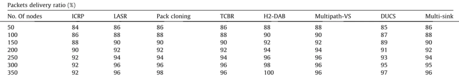
Table 4
Comparison of Packets delivery ratio of proposed routing protocols. Packets delivery ratio (%)
No. Of nodes ICRP LASR Pack cloning TCBR H2-DAB Multipath-VS DUCS Multi-sink
50 84 86 86 86 88 88 85 86 100 86 88 88 88 90 90 87 88 150 88 90 90 90 92 92 89 90 200 90 92 92 92 94 94 91 92 250 92 94 94 94 96 96 93 94 300 92 96 96 96 98 96 95 95 350 92 96 98 96 100 96 97 96
- The design of routing protocol in real world condition taking into consideration with respect to underwater challenges like: high bit error rate, impaired channel due to fading, limited bandwidth, high propagation delay and continuous water pres-sure and salinity.
- To minimize the energy consumption of the sensor node during the deployment in dense and harsh underwater environment. - For battery recharge there should be the investigation is needed
in consideration of water current. 6. Conclusion and future work
The design of routing protocol in underwater environment is also one kind of the challenging issue. This research article focuses the issues in designing of routing protocols based on protocol oper-ations. We have also explained the issues of source initiated, table driven and data aggregation routing protocols based on protocol operations. The article also covers the deployment of sensor nodes, dynamic topology structure, route discovery mechanism, and data forwarding mechanisms of routing protocols based on protocol operation. This research article further focuses the performance analysis through analytical and numerical simulation method. In analytical method we have defined the analysis of architectural parameters and performance metric parameters for proposed rout-ing protocols. The numerical simulation method focuses the per-formance of proposed routing protocols through packets delivery ratio. We observed that the packets delivery ratio of H2-DAB is bet-ter than other proposed routing protocols because the H2-DAB is based on real time parameters.
Future research is based on network performance through qual-ity of service (QoS) for real time applications and securqual-ity is also the major issue for military based applications. In deep underwater environment the node movement is uncontrollable and its’ contin-uous movement can reduce the energy level of the sensor node; so future directions focuses the network scalability and increasing of energy level for sensor nodes are major issues.
References
[1]Kiran JS, Sunitha L, Rao DK, Sooram A. Review on underwater sensor networks: applications, research challenges and time synchronization. Internat J Eng Res Tech 2015.
[2]Darehshoorzadeh A, Boukerche A. Underwater sensor networks: a new challenge for opportunistic routing protocols. Communicat Magazine, IEEE 2015;53:98–107.
[3]Han G, Jiang J, Bao N, Wan L, Guizani M. Routing protocols for underwater wireless sensor networks. Communicat Magazine, IEEE 2015;53:72–8. [4]Javaid N, Jafri M, Ahmed S, Jamil M, Khan Z, Qasim U, et al. Delay-sensitive
routing schemes for underwater acoustic sensor networks. Int J Distrib Sens Netw 2015;2015.
[5]Diao B, Xu Y, An Z, Wang F, Li C. Improving both energy and time efficiency of depth-based routing for underwater sensor networks. Int J Distrib Sens Netw 2015;501:781932.
[6]Jadhao PR, Ghonge MM. Energy efficient routing protocols for underwater sensor networks-a survey. Energy 2015;1.
[7]Jain S, Pilli ES, Govil M, Rao DV. Performance evaluation of congestion-aware routing protocols for underwater sensor networks with multimedia data. Underwater Tech (UT) IEEE 2015;2015:1–6.
[8]Shen J, Tan H, Wang J, Wang J, Lee S. A novel routing protocol providing good transmission reliability in underwater sensor networks. J Internet Tech 2015;16:171–8.
[9]Wahid A, Lee S, Kim D, Lim KS. MRP: a localization-free multi-layered routing protocol for underwater wireless sensor networks. Wireless Pers Commun Aug 2014;77:2997–3012.
[10]Javaid N, Jafri MR, Khan ZA, Qasim U, Alghamdi TA, Ali M. IAMCTD: improved adaptive mobility of courier nodes in threshold-optimized dbr protocol for underwater wireless sensor networks. Int J Distrib Sens Netw 2014. [11]Coutinho RW, Boukerche A, Vieira LF, Loureiro AA. ‘‘GEDAR: geographic and
opportunistic routing protocol with depth adjustment for mobile underwater sensor networks. Communicat (ICC) IEEE Internat Conf 2014;2014:251–6. [12]Climent S, Sanchez A, Capella JV, Meratnia N, Serrano JJ. Underwater acoustic
wireless sensor networks: advances and future trends in physical, MAC and routing layers. Sensors 2014;14:795–833.
[13]Wahid A, Lee S, Kim D. A reliable and energy-efficient routing protocol for underwater wireless sensor networks. Int J Commun Syst 2014;27:2048–62. [14] Umar A, Akbar M, Iqbal Z, Khan Z, Qasim U, Javaid N. Cooperative partner
nodes selection criteria for cooperative routing in underwater WSNs. in Information Technology: Towards New Smart World (NSITNSW), 2015 5th National Symposium on 2015;pp. 1–7.
[15]Akyildiz IF, Pompili D, Melodia T. Underwater acoustic sensor networks: research challenges. Ad Hoc Netw. 2005;3:257–79.
[16]Xu M, Liu GZ, Wu HF, Sun W. Towards robust routing in three-dimensional underwater wireless sensor networks. Int J Distrib Sens Netw 2013. [17]Zhang S, Li D, Chen J. A link-state based adaptive feedback routing for
underwater acoustic sensor networks. Sens J, IEEE 2013;13:4402–12. [18]Llor J, Malumbres MP. Underwater wireless sensor networks: how do acoustic
propagation models impact the performance of higher-level protocols? Sensors Feb 2012;12:1312–35.
[19]Chen Y-S, Lin Y-W. Mobicast routing protocol for underwater sensor networks. Sens J, IEEE 2013;13:737–49.
[20]Casari P, Zorzi M. Protocol design issues in underwater acoustic networks. Comput Commun 2011;34:2013–25.
[21]Liang W, Yu H, Liu L, Li B, Che C. Information-carrying based routing protocol for underwater acoustic sensor network. Mechatron Automat, 2007. ICMA 2007. Internat Conf 2007 2007;2007:729–34.
[22]Carlson EA, Beaujean P-P, An E. Location-aware routing protocol for underwater acoustic networks. OCEANS 2006;2006:1–6.
[23] Sun P, Seah WK, Lee PW. Efficient data delivery with packet cloning for underwater sensor networks. in Underwater Technology and Workshop on Scientific Use of Submarine Cables and Related Technologies, 2007. Symposium on 2007;pp. 34–41.
[24]Ayaz M, Abdullah A, Jung LT. ‘‘Temporary cluster based routing for underwater wireless sensor networks. Informat Tech (ITSim) Internat Sympos in 2010;2010:1009–14.
[25] Ayaz M, Abdullah A. Hop-by-Hop Dynamic Addressing Based (H(2)-DAB) Routing Protocol for Underwater Wireless Sensor Networks. 2009 International Conference on Information and Multimedia Technology, Proceedings 2009;pp. 436–441.
[26] Seah WK, Tan HX. Multipath virtual sink architecture for underwater sensor networks. in OCEANS 2006-Asia Pacific 2007;pp. 1–6.
[27] Domingo MC, Prior R. A distributed clustering scheme for underwater wireless sensor networks. in Personal, Indoor and Mobile Radio Communications, 2007. PIMRC 2007. IEEE 18th International Symposium on 2007;pp. 1–5. [28]Ayaz M, Baig I, Abdullah A, Faye I. A survey on routing techniques in
underwater wireless sensor networks. J Net Comput Appl 2011;34:1908–27. [29] Li T. Multi-sink opportunistic routing protocol for underwater mesh network.
in Communications, Circuits and Systems, 2008. ICCCAS 2008. International Conference on 2008;pp. 405-409.