ETSI TS 102 613
V10.0.0
(2012-09)
Smart Cards;
UICC - Contactless Front-end (CLF) Interface;
Part 1: Physical and data link layer characteristics
(Release 10)
Reference
RTS/SCP-T070138va00
Keywords
smart card
ETSI
650 Route des Lucioles
F-06921 Sophia Antipolis Cedex - FRANCE
Tel.: +33 4 92 94 42 00 Fax: +33 4 93 65 47 16
Siret N° 348 623 562 00017 - NAF 742 C Association à but non lucratif enregistrée à la
Sous-Préfecture de Grasse (06) N° 7803/88
Important notice
Individual copies of the present document can be downloaded from:
http://www.etsi.org
The present document may be made available in more than one electronic version or in print. In any case of existing or perceived difference in contents between such versions, the reference version is the Portable Document Format (PDF). In case of dispute, the reference shall be the printing on ETSI printers of the PDF version kept on a specific network drive
within ETSI Secretariat.
Users of the present document should be aware that the document may be subject to revision or change of status. Information on the current status of this and other ETSI documents is available at
http://portal.etsi.org/tb/status/status.asp
If you find errors in the present document, please send your comment to one of the following services:
http://portal.etsi.org/chaircor/ETSI_support.asp
Copyright Notification
No part may be reproduced except as authorized by written permission. The copyright and the foregoing restriction extend to reproduction in all media.
© European Telecommunications Standards Institute 2012. All rights reserved.
DECTTM, PLUGTESTSTM, UMTSTM and the ETSI logo are Trade Marks of ETSI registered for the benefit of its Members.
3GPPTM and LTE™ are Trade Marks of ETSI registered for the benefit of its Members and of the 3GPP Organizational Partners.
Contents
Intellectual Property Rights ... 6
Foreword ... 6
Introduction ... 6
1 Scope
... 7
2 References
... 7
2.1 Normative references ... 7 2.2 Informative references ... 83
Definitions, symbols, abbreviations and coding conventions ... 8
3.1 Definitions ... 8
3.2 Symbols ... 9
3.3 Abbreviations ... 9
3.4 Void ... 10
3A Coding
conventions
... 10
4
Principle of the Single Wire Protocol ... 10
5 System
architecture ... 11
5.1 General overview ... 11
5.2 TS 102 221 support ... 11
5.3 Configurations ... 11
5.4 Interaction with other interfaces ... 12
6 Physical
characteristics... 12
6.1 Temperature range for card operation ... 12
6.2 Contacts ... 12
6.2.1 Provision of contacts ... 12
6.2.2 Contact activation and deactivation ... 12
6.2.2.1 SWIO contact activation ... 13
6.2.2.2 SWIO contact deactivation... 13
6.2.2.3 Deactivation of the UICC ... 13
6.2.3 Interface activation ... 13
6.2.3.1 Initial interface activation ... 13
6.2.3.2 Subsequent interface activation ... 14
6.2.3.3 Timing parameters ... 15
6.2.3.4 Impact on other interfaces ... 17
6.2.4 Behaviour of a UICC in a terminal not supporting SWP ... 17
6.2.5 Behaviour of terminal connected to a UICC not supporting SWP... 17
6.2.6 Inactive contacts ... 17
7 Electrical
characteristics ... 18
7.1 Operating conditions ... 18
7.1.1 Supply voltage classes ... 18
7.1.2 Vcc (C1) low power mode definition ... 19
7.1.3 Signal S1 ... 19
7.1.4 Signal S2 ... 20
7.1.4.1 Operating current for S2 ... 20
8 Physical
transmission layer ... 20
8.1 S1 Bit coding and sampling time (Self-synchronizing code) ... 20
8.2 S2 switching management ... 21
8.3 SWP interface states management ... 22
8.4 Power mode states/transitions and Power saving mode ... 24
9.2.1 Bit order ... 25
9.2.2 Structure ... 26
9.2.3 Bit Stuffing ... 26
9.2.4 Error detection ... 27
9.3 Supported LLC layers ... 27
9.3.1 Interworking of the LLC layers ... 28
9.4 ACT LLC definition ... 29
9.4.1 SYNC_ID verification process ... 30
10
SHDLC LLC definition ... 31
10.1 SHDLC overview ... 31 10.2 Endpoints ... 31 10.3 SHDLC frame types ... 31 10.4 Control Field ... 32 10.4.1 I-Frames coding ... 32 10.4.2 S-Frames coding ... 32 10.4.3 U-Frames coding ... 3310.5 Changing sliding window size and endpoint capabilities ... 33
10.5.1 RSET frame payload ... 33
10.5.2 UA frame payload ... 34
10.6 SHDLC context ... 34
10.6.1 Constants ... 34
10.6.2 Variables ... 35
10.6.3 Initial Reset State ... 35
10.7 SHDLC sequence of frames ... 35
10.7.1 Nomenclature ... 35
10.7.2 Link establishment with default sliding window size ... 36
10.7.3 Link establishment with custom sliding window size ... 36
10.7.4 Data flow ... 37
10.7.5 Reject (go N back) ... 38
10.7.6 Last Frame loss ... 38
10.7.7 Receive and not ready ... 39
10.7.8 Selective reject ... 39
10.8 Implementation model ... 40
10.8.1 Information Frame emission ... 40
10.8.2 Information Frame reception ... 41
10.8.3 Reception Ready Frame reception ... 42
10.8.4 Reject Frame reception ... 42
10.8.5 Selective Reject Frame reception ... 43
10.8.6 Acknowledge timeout ... 43
10.8.7 Guarding/transmit timeout ... 44
11
CLT LLC definition ... 44
11.1 System Assumptions ... 44
11.2 Overview ... 44
11.2a Supported RF protocols ... 44
11.3 CLT Frame Format ... 45
11.4 CLT Command Set ... 46
11.5 CLT Frame Interpretation ... 46
11.5.1 CLT frames with Type A aligned DATA_FIELD ... 46
11.5.2 Handling of DATA_FIELD by the CLF ... 48
11.5.3 Handling of ADMIN_FIELD ... 48
11.5.3.1 CL_PROTO_INF(A)... 48
11.5.3.2 CL_PROTO_INF(F) ... 49
11.5.3.3 CL_GOTO_INIT and CL_GOTO_HALT ... 50
11.6 CLT Protocol Rules ... 50
11.6.1 Rules for the CLF ... 50
11.6.2 Rules for the UICC ... 51
12.2 CLT data transmission mode for ISO/IEC 14443 Type A ... 52
12.2.1 CLF processing delay when receiving data from the PCD ... 52
12.2.2 CLF processing delay when sending data to the PCD ... 52
12.2.3 Timing values for the CLF processing delay ... 53
12.2.4 Timing value for the CLF processing delay (Request Guard Time) ... 54
12.3 CLT data transmission mode for ISO/IEC18092 212kbps/424kbps passive mode ... 54
Annex A (informative):
Change history ... 55
Intellectual Property Rights
IPRs essential or potentially essential to the present document may have been declared to ETSI. The information pertaining to these essential IPRs, if any, is publicly available for ETSI members and non-members, and can be found in ETSI SR 000 314: "Intellectual Property Rights (IPRs); Essential, or potentially Essential, IPRs notified to ETSI in
respect of ETSI standards", which is available from the ETSI Secretariat. Latest updates are available on the ETSI Web
server (http://ipr.etsi.org).
Pursuant to the ETSI IPR Policy, no investigation, including IPR searches, has been carried out by ETSI. No guarantee can be given as to the existence of other IPRs not referenced in ETSI SR 000 314 (or the updates on the ETSI Web server) which are, or may be, or may become, essential to the present document.
Foreword
This Technical Specification (TS) has been produced by ETSI Technical Committee Smart Card Platform (SCP). The contents of the present document are subject to continuing work within TC SCP and may change following formal TC SCP approval. If TC SCP modifies the contents of the present document, it will then be republished by ETSI with an identifying change of release date and an increase in version number as follows:
Version x.y.z where:
x the first digit:
0 early working draft;
1 presented to TC SCP for information; 2 presented to TC SCP for approval;
3 or greater indicates TC SCP approved document under change control.
y the second digit is incremented for all changes of substance, i.e. technical enhancements, corrections, updates, etc.
z the third digit is incremented when editorial only changes have been incorporated in the document.
Introduction
The present document defines a communication interface between the UICC and a contactless frontend (CLF) in the terminal. This interface allows the card emulation mode independent of the power state of the terminal as well as the reader mode when the terminal is battery powered.
The aim of the present document is to ensure interoperability between a UICC and the CLF in the terminal
independently of the respective manufacturer, card issuer or operator. Any internal technical realization of either the UICC or the CLF is only specified where these are reflected over the interface.
1 Scope
The present document specifies the Single Wire Protocol (SWP). SWP is the interface between the UICC and the CLF. The present document defines:
• Layer1: The physical layer which is responsible for activating, maintaining and deactivating the physical link between the UICC and the CLF. It defines electrical (voltage and current levels, timing and coding of voltage and current levels), mechanical (physical contacts) and functional (data rates) specifications. It also defines the initial communication establishment and the end of the connection.
• Layer 2: The data link layer which is responsible for the physical addressing of the data through frames and Link Protocol Data Units (LPDU). The data link layer is also responsible for error notification, ordered delivery of frames and flow control. This layer can be split into two sub-layers:
- The Medium Access Control (MAC) layer which manages frames.
- The Logical Link Control layer which manages LPDUs and is responsible for the error-free exchange of data between nodes. Three different Logical Link Control layers are defined in the present document.
2 References
References are either specific (identified by date of publication and/or edition number or version number) or
non-specific. For specific references, only the cited version applies. For non-specific references, the latest version of the reference document (including any amendments) applies.
• In the case of a reference to a TC SCP document, a non specific reference implicitly refers to the latest version of that document in the same Release as the present document.
Referenced documents which are not found to be publicly available in the expected location might be found at http://docbox.etsi.org/Reference.
NOTE: While any hyperlinks included in this clause were valid at the time of publication ETSI cannot guarantee their long term validity.
2.1 Normative
references
The following referenced documents are necessary for the application of the present document.
[1] ETSI TS 102 221: "Smart Cards; UICC-Terminal interface; Physical and logical characteristics". [2] ISO/IEC 14443-2: "Identification cards - Contactless integrated circuit(s) cards - Proximity cards -
Part 2: Radio frequency power and signal interface".
[3] ISO/IEC 14443-3: "Identification cards - Contactless integrated circuit(s) cards - Proximity cards - Part 3: Initialization and anticollision".
[4] ISO/IEC 14443-4: "Identification cards - Contactless integrated circuit(s) cards - Proximity cards - Part 4: Transmission protocol".
[5] ISO/IEC 13239: "Information technology - Telecommunications and information exchange between systems - High-level data link control (HDLC) procedures".
[6] ETSI TS 102 600: "Smart Cards; UICC-Terminal interface; Characteristics of the USB interface". [7] ETSI TS 102 223: "Smart Cards; Card Application Toolkit (CAT)".
2.2 Informative
references
The following referenced documents are not necessary for the application of the present document but they assist the user with regard to a particular subject area.
Not applicable.
3
Definitions, symbols, abbreviations and coding
conventions
3.1 Definitions
For the purposes of the present document, the following terms and definitions apply:
card emulation mode: a mode where the UICC emulates a contactless card through the CLF class A operating conditions: terminal or a smart card operating at 5 V ± 10 %
class B operating conditions: terminal or a smart card operating at 3 V ± 10 % class C operating conditions: terminal or a smart card operating at 1,8 V ± 10 % contactless frontend: circuitry in the terminal which:
• handles the analogue part of the contactless communication;
• handles communication protocol layers of the contactless transmission link; • exchanges data with the UICC.
full duplex: Simultaneous bidirectional data flow half duplex: Sequential bidirectional data flow idle bit: bit with logical value 0 sent outside a frame master: entity which provides the S1 signal
reader mode: mode where the UICC act as a contactless reader through the CLF state H: high electrical level of a signal (voltage or current)
state L: low electrical level of a signal (voltage or current) S1: signal from the master to a slave
S2: signal from the slave to the master
slave: entity which is connected to the master and provides the S2 signal
transition sequence: signal sent by the master during RESUME, consisting of the falling edge, the state L period and the rising edge of an idle bit
TS 102 221 [1] interface: asynchronous serial UICC-Terminal interface defined in TS 102 221 [1], using RSET on contact C2, CLK on contact C3 and I/O on contact C7
UICC powering modes:
3.2 Symbols
For the purposes of the present document, the following symbols apply: Gnd Ground
IH Current signalling state H of S2 IL Current signalling state L of S2
T Bit duration
TH1 Duration of the state H for coding a logical 1 of S1 TH0 Duration of the state H for coding a logical 0 of S1 TCLF Processing time of the CLF for a packet of data
TRFn Transfer time of contactless command or response over the RF interface TSWP Transfer time a single SWP packet of date
TUICC Processing time of the UICC for a contactless command
tF Fall time
tR Rise time
Vcc Supply Voltage
VIH Input Voltage (high) VIL Input Voltage (low) VOH Output Voltage (high) VOL Output Voltage (low)
3.3 Abbreviations
For the purposes of the present document, the following abbreviations apply:
ACT ACTivation protocol
CLF ContactLess Frontend
CLK CLocK
CLT ContactLess Tunnelling CMD CoMmanD
CRC Cyclic Redundancy check EOF End Of Frame
FR Frame Repeat
HDLC High level Data Link Control I/O Input/Output
ISO International Organization for Standardization LLC Logical Link Control
LPDU Link Protocol Data Unit
LSB Least Significant Bit MAC Medium Access Control
MSB Most Significant Bit
NFCIP-1 Near Field Communication - Interface and Protocol PCD Proximity Coupling Device
PICC Proximity Integrated Circuit Card REJ Reject
RF Radio Frequency
RFU Reserved for Future Use RNR Receive Not Ready RR Receive Ready RSET ReSeT
SHDLC Simplified High Level Data Link Control SOF Start Of Frame
SREJ Selective Reject
SWIO Single Wire protocol Input/Output SWP Single Wire Protocol
3.4 Void
The content of this clause has been moved to clause 3A.
3A Coding
conventions
For the purposes of the present document, the following coding conventions apply: • All lengths are presented in bytes, unless otherwise stated.
• Each byte is represented by bits b8 to b1, where b8 is the Most Significant Bit (MSB) and b1 is the Least Significant Bit (LSB). In each representation, the leftmost bit is the MSB.
• Hexadecimal values are enclosed in single quotes ('xx').
In the UICC, all bytes specified as RFU shall be set to '00' and all bits specified as RFU shall be set to 0.
4
Principle of the Single Wire Protocol
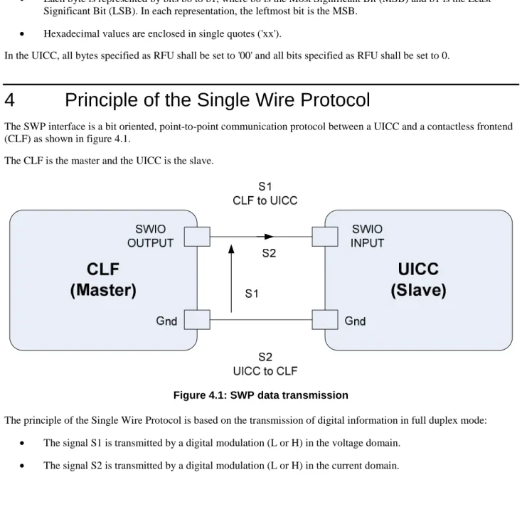
The SWP interface is a bit oriented, point-to-point communication protocol between a UICC and a contactless frontend (CLF) as shown in figure 4.1.
The CLF is the master and the UICC is the slave.
Figure 4.1: SWP data transmission
The principle of the Single Wire Protocol is based on the transmission of digital information in full duplex mode: • The signal S1 is transmitted by a digital modulation (L or H) in the voltage domain.
When the master sends S1 as state H then the slave may either draw a current (state H) or not (state L) and thus transmit S2. With pulse width modulation bit coding of S1, it is possible to transmit a transmission clock, as well as data in full duplex mode. This bit coding of S1 is described in clause 8.1 of the present document. S2 is meaningful only when S1 is in state H.
5 System
architecture
5.1 General
overview
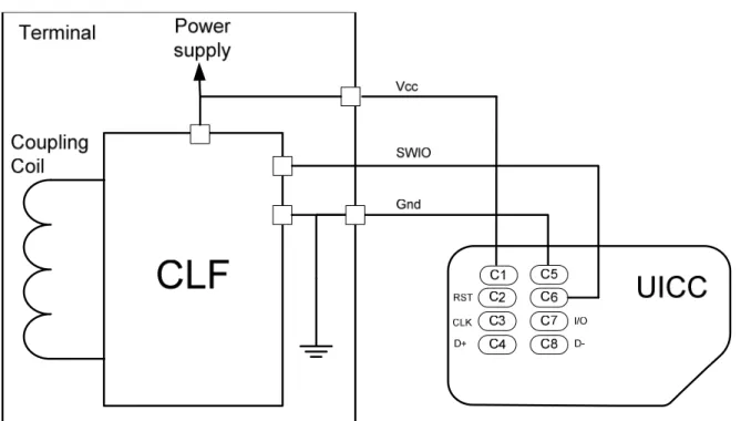
Figure 5.1: CLF-UICC physical link
Figure 5.1 represents the physical link between the CLF and the UICC. The contact C6 of the UICC is connected to the CLF for the transmission of S1 and S2.
5.2
TS 102 221 support
A UICC supporting the SWP interface and a terminal supporting SWP shall remain compliant with TS 102 221 [1]. A terminal supporting the SWP interface utilises contact C6; therefore class A operation cannot be supported. For the low power mode, the electrical characteristics of contact C1 (Vcc) are extended by the present document. Contacts C2, C3 and C7 shall behave as specified in TS 102 221 [1].
5.3 Configurations
The terminal indicates the support of SWP interface in the terminal capability as defined in TS 102 221 [1]. The UICC indicates support of SWP interface in the Global Interface bytes of the ATR as defined in TS 102 221 [1].
When both the terminal and the UICC are supporting the SWP interface, several operation modes become possible in addition to the operation modes already supported by terminal not supporting the SWP interface and the UICC:
• The SWP interface is activated while a session on another terminal-UICC interface is in progress (e.g. the TS 102 221 [1] or TS 102 600 [6] interface). In this case, the different interfaces shall be active concurrently, and therefore actions on the SWP interface shall not disturb the terminal-UICC exchange on the other interfaces and vice-versa.
5.4
Interaction with other interfaces
Communication between a terminal supporting the SWP interface and a UICC supporting the SWP interface take place either over the SWP interface on contact C6 as specified in the present document, or over the interfaces using contacts C2, C3, C4, C7 and C8 as defined in TS 102 221 [1] and TS 102 600 [6]. Signalling on a contact assigned to one interface shall not affect the state of other contacts assigned to another interface. This also applies to the activation sequence of the UICC. The power provided on contacts C1 (Vcc) and C5 (Gnd) shall cover the power consumption of all active interfaces of the UICC.
Operation of the SWP interface after activation shall be independent from operation of other interfaces (e.g. the TS 102 221 [1] or TS 102 600 [6] interface) that may be implemented on the UICC.
Any reset signalling (RSET signal on contact C2 as specific to the TS 102 221 [1] interface or logical reset on TS 102 600 [6] interface) shall only affect the UICC protocol stack related to these interfaces. SWP-related processes shall not be affected by another interface reset signal.
A logical reset signalling on the data link layer (SHDLC RSET) over the SWP interface as well as activation and deactivation of SWP interface shall not affect any of the other interfaces.
6 Physical
characteristics
6.1
Temperature range for card operation
In the present document, all parameter values for the SWP interface shall apply for the standard temperature range for storage and full operation as defined in TS 102 221 [1].
6.2 Contacts
6.2.1 Provision
of
contacts
Vcc (contact C1) and Gnd (contact C5) provided in the UICC shall be reused by the terminal to provide power supply. SWIO (contact C6) of the UICC shall be used for data exchange between the UICC and the CLF.
6.2.2
Contact activation and deactivation
The terminal shall connect, activate and deactivate contacts C2, C3 and C7 of the UICC in accordance with the operating procedures specified in TS 102 221 [1] and the contacts C4 and C8 in accordance with the operating
procedures specified in TS 102 600 [6] when these interfaces are used. The terminal shall activate the contact C1 (Vcc) according to the TS 102 221 [1].
A terminal may decide not to perform the contact and interface activation of SWP if it detected in either this or a previous card session that the UICC does not support the SWP.
6.2.2.1 SWIO
contact
activation
As long as Vcc (contact C1) is not activated, the terminal shall keep SWIO (contact C6) deactivated (S1 state L). The terminal activates Vcc (contact C1) in order to either activate the SWP interface or Vcc (contact C1) is activated due to the activation of another interface on the UICC.
The activation of the SWIO (contact C6) takes place when the terminal sets the SWIO signal from state L to state H. This indicates to the UICC to activate its SWP interface.
6.2.2.2 SWIO
contact
deactivation
In order to deactivate SWIO (contact C6), the terminal shall set SWP to the DEACTIVATED state as defined in clause 8.3.
6.2.2.3
Deactivation of the UICC
In addition to the deactivation as given in TS 102 221 [1] and TS 102 600 [6] the terminal shall deactivate SWIO (contact C6) before deactivating Vcc (contact C1).
6.2.3 Interface
activation
6.2.3.1 Initial
interface
activation
The following process shall take place after the contact activation of SWIO (contact C6).
This process makes use of SWP interface states management described in clause 8.3 and of the ACT LLC layer as described in clause 9.4.
The sequence is as follows:
• The UICC shall indicate that it is ready to exchange data via SWP by resuming SWP.
- In case the CLF does not detect an SWP resume by the UICC, the CLF shall assume that the UICC does not support the SWP interface and the CLF shall deactivate SWIO (contact C6).
• The CLF shall put SWP into ACTIVATED state.
- In case the UICC does not detect the SWP ACTIVATED state, the UICC shall set S2 to state L not later than TS2_INHIBIT after the UICC has put S2 in state H. The UICC shall not respond to further attempts from the CLF to communicate via SWP and shall wait for UICC deactivation or shall retrieve
information about SWP capability of the terminal via any other UICC interface (see clause 6.2.4). • The UICC shall send the first ACT_SYNC frame and wait for the first frame from the CLF.
• When the CLF has received the first ACT_SYNC frame from the UICC, the CLF shall take the following actions:
- If the CLF has received a correct ACT_SYNC frame and the terminal provides full power mode, the CLF shall respond with an ACT_POWER_MODE frame with FR bit set to 0 indicating full power mode. - If the CLF has received a correct ACT_SYNC frame and the terminal provides low power mode the CLF
shall consider the initial interface activation as being successful and shall not send further ACT frames. • When the CLF has received a corrupted frame or no frame the CLF shall request the UICC to repeat the last
ACT_SYNC frame by sending an ACT_POWER_MODE frame with FR bit set to 1 indicating the current terminal power mode.
• When the UICC has received an ACT_POWER_MODE frame from the CLF, the UICC shall take the following actions:
- If the UICC has received a correct ACT_POWER_MODE and the FR bit of this frame is 1, then the UICC shall repeat the last ACT frame it had sent. If the FR bit is 0 then the UICC shall respond with an ACT_READY frame.
- If the UICC has received a corrupted frame, the UICC shall not respond.
• When the CLF has received an ACT frame in response to an ACT_POWER_MODE frame, the CLF shall take the following action:
- the CLF shall consider the initial interface activation as being successful and shall not send further ACT frames if it has received:
an ACT_SYNC frame in response to an ACT_POWER_MODE frame with FR bit set to 1; or an ACT_READY frame in the case that the CLF has previously correctly received the first ACT_SYNC frame for the UICC.
• When the CLF has received a corrupted frame, the CLF shall request the UICC to repeat the last ACT frame by sending an ACT_POWER_MODE frame with FR bit set to 1 indicating the current terminal power mode. • When the CLF has not received an ACT frame in response to an ACT_POWER_MODE frame, the CLF shall
take the following actions:
- In this case, the CLF shall request the UICC to repeat the last ACT frame by sending an ACT_POWER_MODE frame with FR bit set to 1 indicating the current terminal power mode. - The CLF shall not send more than three ACT_POWER_MODE frames with the FR bit set to 1. The CLF shall treat a received ACT frame like a corrupted frame when it does not occur in the order defined in the sequence above.
If the interface activation was not successful the CLF shall assume that the UICC does not support SWP interface. In this case the CLF shall deactivate SWIO (contact C6).
All ACT-SYNC frames sent by UICC during initial interface activation shall contain the ACT_INFORMATION field.
6.2.3.2 Subsequent
interface
activation
The initial interface activation sequence shall also be applied after the transition of S1 to state H from the state DEACTIVATED, with the following modifications:
• The UICC shall not send an ACT_INFORMATION field in any of the ACT frames.
• When the CLF has received the first ACT_SYNC frame from the UICC, the CLF shall take the following action:
- If the CLF has received a correct ACT_SYNC frame, the CLF shall immediately consider the subsequent interface activation as being successful and shall not send further ACT frames.
6.2.3.3 Timing
parameters
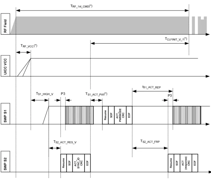
Figure 6.1 shows the timing conditions for the initial interface activation after Vcc (contact C1) activation, for the case when an ACT_POWER_MODE frame is sent. Table 6.1 gives the timing values.
R F Fi el d U IC C V C C S W P S 1 S W P S 2 Re su me SO F AC T_ PW RM OD E CR C EO F Re su me SO F AC T (re sp on se ) CR C EO F Re su me SO F EO F AC T_ SY NC _ID CR C
NOTE 1: The relationship to RF-field appearance is shown for information only.
NOTE 2: Timing marked (*) are informative. The compliancy to the startup time of the RF application TRF_1st_CMD (for ISO/IEC 14443-3 [3]: 5 msec from RF-field 1.5A/m to be able to receive REQA, REQB) is achieved by the CLF by balancing TRF_VCC, TS1_ACT_PW, TCLFINIT and the SWP bit rate properly. The system is designed in a way, that the CLF may keep the timing constraints when relying on the 1st SYNC_ID
transmission. In case this fails it is up to the CLF to request resending SYNC_ID and go for the next REQA, REQB.
NOTE 3: The value of TS1_ACT_REP implemented by the CLF should be greater than TS1_ACT_FRP + the SWP resume time. This is to ensure that an ACT frame from the CLF is not sent when an ACT(response) frame from the UICC is sent.
Table 6.1: Timing parameters for initial interface activation on RF-field appearance
Symbol Parameter Minimum Maximum Unit
TS1_HIGH_V SWIO (contact C6) activation time after Vcc
(contact C1) activation. 1 000 - µs TS2_ACT_RES_V UICC resumes SWP for sending 1st
ACT_SYNC frame. 0 700 µs
TS2_ACT_FRP
UICC responds to ACT_POWER_MODE frames (calculated from last bit of EOF to SWP resume or wakeup sequence).
0 2 000 µs
TS2_INHIBIT UICC detection timeout (see clause 6.2.3.1) - 100 ms
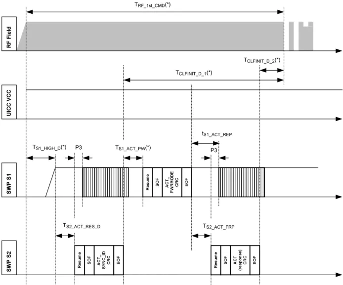
The interface activation from the SWP DEACTIVATED state is given in figure 6.2 for the case when an ACT_POWER_MODE frame is sent. Additional timing values are given in table 6.2.
R F Fi el d U IC C V C C S W P S 1 S W P S 2 TRF_1st_CMD(*) TCLFINIT_D_1(*) Re su me SO F EO F AC T_ SY NC _ID CR C TS2_ACT_RES_D TS1_HIGH_D(*) Re su me SO F AC T_ PW RM OD E CR C EO F TS1_ACT_PW(*) Re su me SO F AC T (re sp on se ) CR C EO F TS2_ACT_FRP tS1_ACT_REP TCLFINIT_D_2(*) P3 P3
NOTE 1: The relationship to RF-field appearance is shown for information only.
NOTE 2: Timing marked (*) are informative. The compliancy to the startup time of the RF application TRF_1st_CMD (for ISO/IEC 14443-3 [3]: 5 ms from RF-field 1,5 A/m to be able to receive REQA, REQB) is achieved by the CLF by balancing TS1_HIGH_D, TS1_ACT_PW, TCLFINIT_D and the SWP bit rate properly. The system is designed in a way, that the CLF may keep the timing constraints when relying on the 2nd SYNC_ID
transmission in case the 1st transmission fails.
Table 6.2: Additional timing parameters for the interface activation from the deactivated state on RF-field appearance
Symbol Parameter Minimum Maximum Unit
TS2_ACT_RES_D UICC resumes SWP for sending 1st
ACT_SYNC frame 0 500 µs
6.2.3.4
Impact on other interfaces
Depending on the power state of the UICC the following conditions for the interfaces shall apply:
• If the UICC is in "low power mode" the terminal shall not activate the TS 102 221 [1] interface and if the UICC supports the USB interface according to TS 102 600 [6], it shall not perform an attachment on the USB interface.
• If the UICC is in "full power mode", the terminal may independently activate any other UICC interfaces. • If the UICC was activated according to TS 102 221 [1], an additional activation of the SWP interface shall be
considered as selected application on the UICC.
6.2.4
Behaviour of a UICC in a terminal not supporting SWP
The UICC shall take care of terminals having C6 contact connected with low impedance to Vcc or electrically isolated. When the UICC detects that the contact C6 is not connected to Vcc it shall connect the C6 contact with a low
impedance to Gnd within 2 s after detecting that the terminal does not indicate the support of SWP interface. NOTE: Implementation has to take care to minimize SWP related power consumption.
6.2.5
Behaviour of terminal connected to a UICC not supporting SWP
When the terminal detects that the UICC does not support SWP, it shall keep SWIO in the deactivated state (state L).
6.2.6 Inactive
contacts
7 Electrical
characteristics
7.1 Operating
conditions
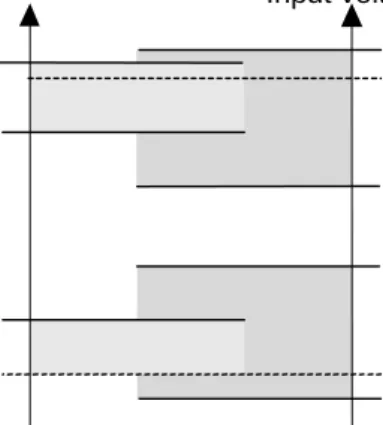
The voltage levels for the CLF (Master) and the UICC (Slave) signal S1 are illustrated in figure 7.1.
1,8 V
Gnd
CLF (Master)
Valid range for S1 high
Valid range for S1 low Input voltage VIH max VIH min VIL max VIL min VOH max VOH min VOL max UICC (Slave)
Figure 7.1: Voltage definitions for the signal S1
VIH and VIL refers to the receiving device signal level (Slave). VOH and VOL refers to the sending device signal level (Master). All voltages are referenced to Gnd.
The SWP interface uses a second signal S2 which is the current from the master to the slave and allows data to be sent back from the slave to the master. S2 values are defined when S1 is state H. The current levels for S2 are defined in clause 7.1.4.1, as shown in figure 7.2.
0 S2 (Current) stateH stateL IH max IH min IL max IL min
Figure 7.2: Definitions of the current level for S2 on SWIO
7.1.1 Supply
voltage
classes
7.1.2 V
cc(C1) low power mode definition
When the system operates in low power mode table 7.1 applies.
Table 7.1: Electrical characteristics of VCC in low power mode
Symbol Conditions Minimum Maximum Unit
VCC Class C 1,62 1,98 V
ICC Class C 5 mA
NOTE: The current value is averaged over 1 ms.
The maximum current in the table 7.1 is defined for the UICC. The terminal may deliver more. The voltage value shall be maintained within the specified range despite transient power consumption as defined in table 7.2.
Table 7.2: Spikes on ICC
Class Maximum charge
(see note 1)
Maximum duration Maximum variation of ICC (see note 2)
C 6 nA.s 400 ns 30 mA
NOTE 1: The maximum charge is half the product of the maximum duration and the maximum variation. NOTE 2: The maximum variation is the difference in supply current with respect to the average value.
7.1.3 Signal
S1
S1 is a signal in the voltage domain to transmit data from the CLF to the UICC on SWIO (contact C6). S1 shares the same electrical contact as S2 as defined in clause 7.1.4. Electrical characteristics of S1 are given in tables 7.3 and 7.4. Currents are considered positive, if they are flowing into the UICC or out of the CLF.
Table 7.3: Electrical characteristics of SWIO for S1 under normal operating conditions in voltage class B
Symbol Parameter Conditions Minimum Maximum Unit
VOH Output High Voltage (high) IL min≤ I ≤ IH max
(see note 2) 1,40 1,98 (see note 1) V VOL Output Low Voltage (low) -20 µA ≤ I ≤ 0 µA 0 (see note 1) 0,3 V VIH Input High Voltage (high) 1,13 2,28 V VIL Input Low Voltage (low) -0,3 0,48 V NOTE 1: To allow for overshoot the voltage on SWIO shall remain between -0,3 V and VOH max + 0,3 V during
dynamic operation.
NOTE 2: The values of IL min and IH max are given in clause 7.1.4.1.
Table 7.4: Electrical characteristics of SWIO for S1 under normal operating conditions in voltage class C
Symbol Parameter Conditions Minimum Maximum Unit
VOH Output High Voltage (high) IL min≤ I ≤ IH max
(see note 2) 0,85 x VCC VCC (see note 1) V VOL Output Low Voltage (low) -20 µA ≤ I ≤ 0 µA 0 (see note 1) 0,15 x VCC V VIH Input High Voltage (high) 0,7 x VCC VCC+0,3 V VIL Input Low Voltage (low) -0,3 0,25 x VCC V NOTE 1: To allow for overshoot the voltage on SWIO shall remain between -0,3 V and VCC+ 0,3 V during
dynamic operation.
7.1.4 Signal
S2
S2 is a signal in the current domain to transmit data from the UICC to the master. S2 shares the same electrical contact as S1 (contact C6). In this clause the electrical characteristics of S2 are described.
7.1.4.1
Operating current for S2
S2 is considered as in state H when the current drawn on SWIO is between IH min and IH max and is considered in state L when the current drawn on SWIO is between IL min and IL max.
Table 7.5: Electrical characteristics of SWIO for S2 under normal operating conditions
Symbol Parameter Conditions Minimum Maximum Unit
IH High Current VIHmin≤ S1 ≤ VIHmax 600 1 000 µA IL Low Current VIHmin≤S1 ≤ VIHmax 0 20 µA
8
Physical transmission layer
8.1
S1 Bit coding and sampling time (Self-synchronizing code)
The bit coding of S1 is illustrated in figure 8.1.
V
Logical 1
Logical 0
t tS1
V T 3/4 T 1/4 T Figure 8.1: Bit-coding of S1The nominal duration of the state H for a logical 1 is 0,75 x T, the nominal duration of the state H for a logical 0 is 0,25 x T.
All bits shall be transmitted consecutively. A bit is defined as having two rising edges. These rising edges constitute the beginning and end of the bit period. The bit-duration may be different for each transmitted bit.
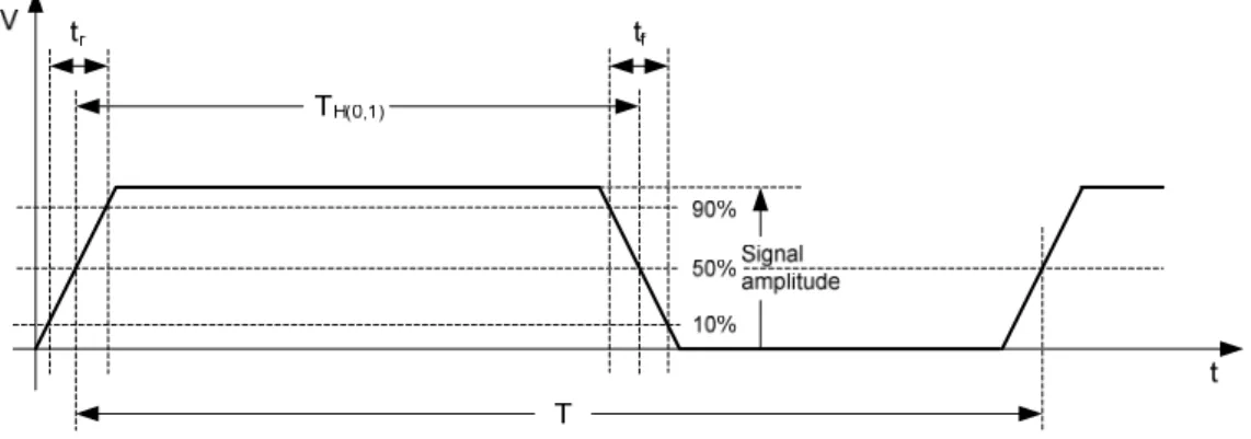
Figure 8.2: S1 waveform
The input capacitance of the UICC (CLOAD ) on the C6 contact shall not exceed 10 pF. Table 8.1 gives S1 waveform timing.
Table 8.1: S1 waveform timings
Symbol Parameter Conditions Minimum Nominal Maximum Unit
tf Fall time CLOAD≤ 10 pF T < 5 000 ns 5 ns - 0,05 x T CLOAD≤ 10 pF T > 5 000 ns 5 ns (see note 3) - 250 ns (see note 3) tr Rise time CLOAD≤ 10 pF T < 5 000 ns 5 ns - 0,05 x T (see note 1) CLOAD≤ 10 pF T > 5 000 ns 5 ns (see note 3) - 250 ns (see notes 1 and 3) TH1 Duration of the state H for
coding a logical 1 of S1 0,70 x T 0,75 x T 0,80 x T TH0 Duration of the state H for
coding a logical 0 of S1 0,20 x T 0,25 x T 0,30 x T T
(see note 2)
Default bit duration 1 - 5 µs
Extended bit duration 0,590 - 10 µs NOTE 1: Valid for the leading edge and the trailing edge of each bit.
NOTE 2: Extended bit durations are indicated as per table 9.3.
NOTE 3: These timing values shall also apply for SWIO contact activation and transitions to and from DEACTIVATED state.
8.2
S2 switching management
S2 is valid only when S1 is in state H. The UICC (Slave) shall only perform switching of S2 when S1 is in state L, or when resuming SWP (the only occasion when S2 is allowed to be switched while S1 is in state H due also to the SUSPENDED state of SWIO). Figure 8.3 illustrates the timing of S2 related to S1.
S1
S2
V
OHminLogical 0
Logical 1
V
A
S2 is valid
I
HminI
LmaxS2 is not valid
Figure 8.3: S2 timing8.3
SWP interface states management
The SWP has three states: ACTIVATED:
In this state master and slave are sending bits.
SWP remains in this state until a SUSPEND transition occurs. SUSPENDED:
In this state S1 is in state H and S2 is in state L. This state is the initial state of SWP at activation of the SWP interface. SWP remains in this state until a RESUME or DEACTIVATE transition occurs.
DEACTIVATED:
In this state the signal S1 is in state L and the signal S2 is in state L. SWP remains in this state until an ACTIVATE transition occurs.
NOTE: When the UICC is operating in full power mode, the master should not put SWP in that state if the terminal does not provide means for re-activation of this interface.
The transitions between these states are defined as follows:
RESUME:
Transition from SUSPENDED state to ACTIVATED state. Both the master and the slave may execute a RESUME to bring SWP into ACTIVATED state.
If the master resumes, the slave may start sending frames already during the P2 idle bits.
If the last information sent by the master was the SHDLC acknowledgement to an indication via an upper layer that the UICC requires no more activity on this interface then the master resumes switching SWP to the DEACTIVATED state as described in DEACTIVATE followed by switching SWP to the ACTIVATED state as described in ACTIVATE. The slave resumes by drawing a current (S2 in state H).
If all of the following conditions are met, the master shall respond by sending a transition sequence in less than P6max time:
• The UICC has indicated support of extended resume (see clause 9.4).
• The last information the master has received is an indication via an upper layer that the UICC requires no more activity on this interface.
• SWP is in SUSPENDED state for at least a time of P7.
Else the master shall respond by sending a transition sequence in less than P3max time.
At the end of the transition sequence, SWP enters the ACTIVATED state. The delay after the transition sequence until the SOF sent by the slave shall not exceed 4 bits.
Figure 8.4: Void
SUSPEND:
If there is no activity on SWP, other than idle bits during P1 time, the master may switch SWP to the SUSPENDED state by maintaining S1 in state H.
DEACTIVATE:
The master may switch SWP to the DEACTIVATED state by maintaining SWIO in state L for longer than P4 time if one of the following conditions is met:
• The last information sent by the master on SWP was the SHDLC acknowledgment to an indication via an upper layer that the UICC requires no more activity on this interface and SWP has entered SUSPENDED state.
• SWP is in SUSPENDED state for a time of P5 and the CLF:
- does not detect an RF field compliant with ISO/IEC 14443-2 [2] or ISO/IEC 18092 [8]; and - does not generate an RF field on request from the UICC.
ACTIVATE:
If SWP is in DEACTIVATED state, the interface activation procedure as described in clause 6.2.3 shall be applied. The slave may request activation of the interface by using the ACTIVATE command as defined in TS 102 223 [7].
Figure 8.5 illustrates an example of SWP activities. ACTIVATED SUSPENDED P1 ACTIVATED P3 SUSPENDED P4 DEACTIVATED S W P in te rfa ce ac tiv at io n by slave S1 S2 ACTIVATED SUSPENDED P1 ACTIVATED SUSPENDED P4 DEACTIVATED S W P in te rfa ce ac tiv at io n by master P2 S1 S2 P1 P1 Transition sequence Transition sequence
Figure 8.5: SWP states and transitions
Table 8.2 gives SWP management timings.
Table 8.2: SWP Management Timing
Symbol Parameter Minimum Maximum Unit
P1 Suspend sequence 7 - Bit
P2 Resume by master sequence 8 8 Bit
P3 Resume by slave time - 5 µs
P4 Deactivation time 100 - µs
P5 SWP inactivity timeout 15 - ms
P6 Extended resume by slave time - 20 ms
P7 SWP Suspended state 20 ms
8.4
Power mode states/transitions and Power saving mode
When the terminal activates Vcc (contact C1) the UICC shall enter the initial power state with the current consumption of the UICC complying with the value in TS 102 221 [1] for "power consumption of the UICC during ATR at 4 MHz external clock frequency".
The UICC shall enter low power mode
• when this mode is indicated in a power mode frame during initial SWP interface activation, or
• when the UICC receives the first non-ACT frame without having received a power mode frame during initial SWP interface activation.
The UICC shall enter full power mode
• when this mode is indicated in a power mode frame during initial SWP interface activation, or • if the conditions for full power mode on another interface are fulfilled.
The CLF shall indicate full power mode if sufficient power from the terminal's power supply (e.g. battery) is available. During the initial power state, the UICC may already increase its current consumption to the value defined for low
The UICC shall be in power saving mode when all of the following conditions for activated interfaces are given: • clock stop mode according to TS 102 221 [1] if this interface is activated (if UICC is in full power mode); • suspend mode according to TS 102 600 [6] if this interface is activated (if UICC is in full power mode); • one of the following conditions is met:
- The SWP is in DEACTIVATED state for 10 ms.
- The last information received on SWP was the SHDLC acknowledgment to the indication via the upper layer that the UICC requires no more activity on this interface and the SWP is in SUSPENDED state for 10 ms.
When the UICC is in power saving mode it shall not exceed the current defined for clock stop mode in TS 102 221 [1] or the limit given for suspend mode in TS 102 600 [6] whatever the interface is activated.
The UICC shall exit the power saving mode when at least one of the UICC interfaces is resumed from these conditions. NOTE: In full power mode, all the resources in the terminal (e.g. display, keyboard, etc.) may not be available for
the UICC applications.
9
Data link layer
9.1 Overview
The Data Link layer manages LPDUs (Link Protocol Data Units) as illustrated in figure 9.1. This layer can be divided into two sub-layers:
• MAC layer is in charge of framing.
• LLC layer is in charge of error management and flow control.
Packet
LPDU
LLC layer
MAC layer
Frame
Figure 9.1: Data link layer overview
9.2
Medium Access Control (MAC) layer
9.2.1 Bit
order
9.2.2 Structure
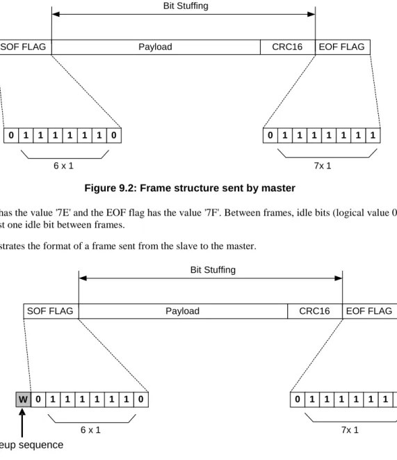
Figure 9.2 illustrates the format of a frame sent from the master to the slave.
Payload
SOF FLAG CRC16 EOF FLAG
0 1 1 1 1 1 1 0
6 x 1
0 1 1 1 1 1 1 1
7x 1 Bit Stuffing
Figure 9.2: Frame structure sent by master
The SOF flag has the value '7E' and the EOF flag has the value '7F'. Between frames, idle bits (logical value 0) are sent. There is at least one idle bit between frames.
Figure 9.3 illustrates the format of a frame sent from the slave to the master.
Wakeup sequence
Payload
SOF FLAG
CRC16
EOF FLAG
0
1
1
1
1
1
1
0
6 x 1
0
1
1
1
1
1
1
1
7x 1
Bit Stuffing
W
Figure 9.3: Frame structure sent by slave
A wakeup sequence, consisting of a bit with logical value 1 shall be inserted before each frame sent from the slave to the master.
In the case that the master starts suspending the interface at the same point in time when the slave starts sending the wakeup sequence, the bit with logical value 1 is transformed into a resume by slave sequence which brings SWP back to ACTIVATED state.
The payload size is limited to 30 bytes. The CRC field is 16 bits long.
9.2.3 Bit
Stuffing
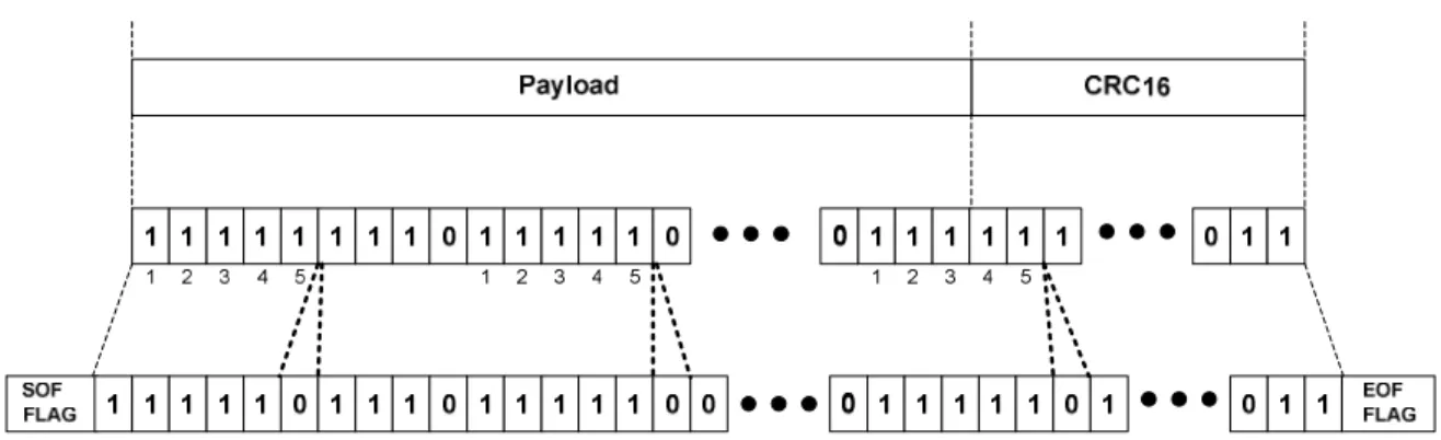
In order to unambiguously detect the SOF and EOF flags, zero bit stuffing shall be employed by the transmitting entity when sending the payload and the CRC on SWP. After five consecutive bits with the logical value 1, a bit with the
An example of a zero bit stuffed sequence is given in figure 9.4.
Figure 9.4: Bit stuffing
9.2.4 Error
detection
The detection of errors in a frame shall be based on the 16-bit frame checking sequence as given in ISO/IEC 13239 [5]. The CRC polynomial is:
X16+X12+ X5+1.
Its initial value is 0xFFFF.
The CRC is computed on the bits between SOF and EOF both excluded.
9.3 Supported
LLC
layers
Three Logical Link Control (LLC) layers using the previously defined MAC layer are defined in the present document: • SHDLC: This is the generic LLC used during most of the contactless transactions. SHDLC is defined in
clause 10. Support of this LLC in mandatory in the CLF and the UICC.
• CLT: This LLC is used for some proprietary protocol handling. CLT mode is defined in clause 11 CLT LLC definition. Support of this LLC is optional in the CLF and optional (application dependant) in the UICC. • ACT: This LLC consist of frames used during interface activation. Support of this LLC is mandatory in the
CLF and the UICC.
Table 9.1: LLC Control field coding
Frame Types Bit Field
8 7 6 5 4 3 2 1
RFU 0 0 All settings
ACT 0 1 1 ACT type
CLT 0 1 0 CLT CMD
SHDLC 1 All settings
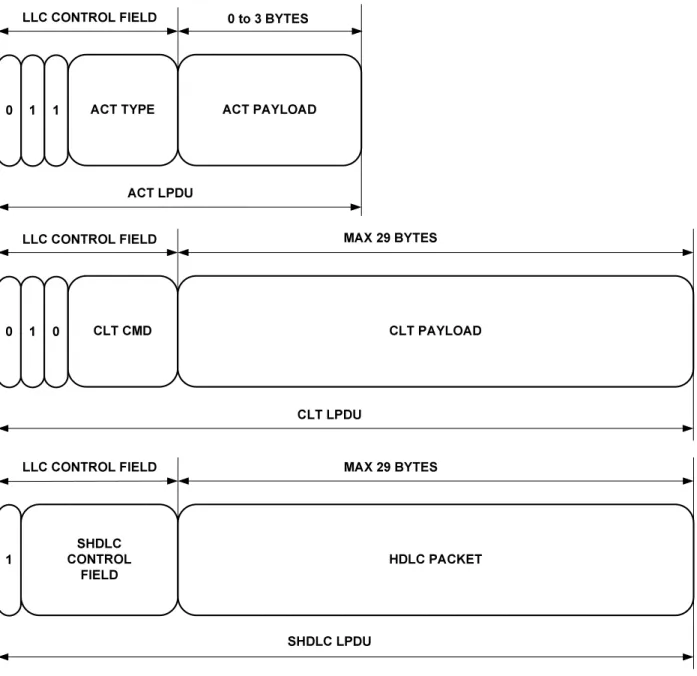
The control field is the first byte of the SWP frame payload. Definition for the different LLC layers can be found in table 9.1.
SHDLC CONTROL FIELD 1 HDLC PACKET MAX 29 BYTES SHDLC LPDU CLT CMD 0 CLT PAYLOAD MAX 29 BYTES CLT LPDU 1 0 ACT TYPE 0 ACT PAYLOAD
LLC CONTROL FIELD 0 to 3 BYTES
ACT LPDU 1 1
LLC CONTROL FIELD
LLC CONTROL FIELD
Figure 9.5: LPDU structure of the 3 defined LLC layers
9.3.1
Interworking of the LLC layers
After SWIO (contact C6) activation or after the transition of S1 to state H from DEACTIVATED state, the SHDLC link shall be not established and no CLT session shall be open. The ACT LLC shall be used by the UICC and by the CLF.
The CLF shall take the following action after successful activation of the SWP:
• If the CLF has data to be sent to the UICC (e.g. due to a contactless transaction) that requires the use of the CLT LLC, it shall initiate a CLT LLC session.
• Otherwise it shall start the establishment of an SHDLC link as soon as possible. NOTE: The CLF will always send the first non-ACT frame after activation of the SWP.
After the UICC and the CLF have established the SHDLC link or opened the CLT session, the UICC and the CLF shall not send ACT LLC frames; received ACT LLC frames shall be ignored.
Once the SHDLC link is established, a CLT session shall not invalidate the SHDLC context and the endpoint capabilities negotiated during the SHDLC link establishment.
To enter the CLT LLC from ACT LLC or SHDLC LLC, the CLT session shall be opened as described in clause 11.6. The CLF shall open a CLT session only when all SHDLC I-Frames are acknowledged. SHDLC LLC frames received by the UICC or by the CLF during a CLT session close the CLT session.
In case the UICC or the CLF receives a corrupted SWP frame, then the receiving entity shall use the error recovery procedure defined for the LLC of the last correctly received SWP frame. Immediately after SWIO (contact C6) activation or after the transition of S1 to state H from DEACTIVATED state, the error handling of the ACT LLC shall apply.
9.4
ACT LLC definition
The ACT LPDU shall be structured according to figure 9.6.
Figure 9.6: ACT LPDU structure
Coding of ACT TYPE:
• The meaning of FR in a frame when received by the UICC is described in clause 6.2.3.1. • Meaning of FR in a frame when received by the CLF:
- The CLF shall ignore the FR bit.
A frame sent from the UICC to the CLF shall have the FR bit set to 0. • Meaning of INF in a frame when received by the CLF:
- INF = 1: Last byte of ACT payload contains the ACT_INFORMATION field. - INF = 0: ACT_INFORMATION field not available.
• Meaning of INF in a frame when received by the UICC: - The UICC shall ignore the INF bit.
The meaning of ACT_CTRL and ACT_DATA is given in table 9.2.
Table 9.2: Meaning of ACT_CTRL and ACT_DATA
ACT_CTRL Meaning ACT_DATA FIELD
000 ACT_READY Sent from UICC to CLF
0 Byte
010 ACT_POWER_MODE Sent from CLF to UICC to indicate the power
mode for the UICC.
1 Byte '00': Low power mode
'01': Full power mode (see Note) 001 ACT_SYNC
Sent from UICC to CLF to control the SYNC_ID verification process.
2 Byte SYNC_ID
All other values (see note)
NOTE: All other values are reserved for future use. These values shall not be set by the transmitting entity and shall be ignored by the receiving entity.
ACT_INFORMATION: By sending this field appended to an ACT_SYNC frame, the UICC indicates extended capabilities as defined in table 9.3.
Table 9.3: Extended capability indication in ACT_INFORMATION field
Bit field Value Meaning
8 .. 4 00000 RFU (see note) 3 1
0
The UICC supports extended resume. The UICC does not support extended resume. 2 1
0
Extended SWP bit durations down to 0,590 µs are supported No lower extended SWP bit durations beyond the default range are
supported 1 1
0
Extended SWP bit durations up to 10 µs are supported No higher extended SWP bit durations beyond the default range are
supported
NOTE: These bits shall not be set by the UICC and shall be ignored by the CLF.
The CLF may use extended SWP bit durations as indicated in the ACT_INFORMATION field after it has received an ACT_SYNC frame with an ACT_INFORMATION field during the initial interface activation.
9.4.1 SYNC_ID
verification process
The purpose of the SYNC_ID verification is to check the identity of the UICC. The SYNC_ID verification process consists of the following steps:
• The UICC presents the SYNC_ID to the CLF in an ACT_SYNC frame. The presented SYNC_ID is named
verification data.
• The CLF compares verification data with identity reference data. The provisioning of the identity reference
data is out of scope of the present document.
For the SYNC_ID verification, the following conditions shall apply: • The CLF and the UICC shall support SYNC_ID verification.
• The SYNC_ID verification shall always be executed when the SWP interface is activated (see clause 6.2.3). The CLF shall perform the SYNC_ID verification process based on ACT frames received from the UICC as outlined
If the CLF evaluates that verification data and identity reference data values are equal, the identity check is successful. If the values are not equal, the identity check failed and the CLF shall not open a CLT session.
NOTE: Within the scope of the present document, only the mechanism that the CLF checks the identity of the UICC is described. The consequences of a failed identity check and mechanisms to recover from this state are specified in a higher layer.
10 SHDLC
LLC
definition
10.1 SHDLC
overview
The SWP SHDLC layer as defined in the present document is a simplified version of ISO's High-level Data Link Control (HDLC ISO/IEC 13239 [5]) specification. It is responsible for the error-free transmission of data between network nodes.
The SHDLC layer shall ensure that data passed up to the next layer has been received exactly as transmitted (i.e. error free, without loss and in the correct order). Also, the SHDLC layer manages the flow control, which ensures that data is transmitted only as fast as the receiver may receive it.
SHDLC ensures a minimum of overhead in order to manage flow control, error detection and recovery. If data is flowing in both directions (full duplex), the data frames themselves carry all the information required to ensure data integrity.
The concept of a sliding window is used to send multiple frames before receiving confirmation that the first frame has been received correctly. This means that data may continue to flow in situations where there may be long "turnaround" time lags without stopping to wait for an acknowledgement.
10.2 Endpoints
SHDLC communication occurs between two endpoints. Those endpoints are identified as the CLF and the UICC. There is no priority of traffic.
SHDLC
CLF UICC
Figure 10.1: Endpoints
10.3
SHDLC frame types
SHDLC uses several types in order to transfer data and to manage or supervise the communication channel between the two endpoints (ends of the communication channel):
• I-Frames (Information frames): Carry upper-layer information and some control information. I-frame functions include sequencing, flow control, and error detection and recovery. I-frames carry send and receive sequence numbers.
• S-Frames (Supervisory Frames): Carry control information. S-frame functions include requesting and suspending transmissions, reporting on status, and acknowledging the receipt of I-frames. S-frames carry only receive sequence numbers.
• U-Frames (Unnumbered Frames): Carry control information. U-frame functions include link setup and disconnection, as well as error reporting. U-frames carry no sequence numbers.
10.4 Control
Field
The SHDLC control field has the structure described in table 10.1, including the first bits of the payload.
Table 10.1: SHDLC Control field coding
Frame Types Bit Field
8 7 6 5 4 3 2 1
I 1 0 N(S) N(R)
S 1 1 0 TYPE N(R)
U 1 1 1 M
where:
• N(S): Number of the information frame.
• N(R): Number of next information frame to receive. • TYPE: Type of S-Frame.
• M: Modifier bits for U-Frame.
The size of the sliding window is four frames by default. Frames types may be interleaved. For example, a U-Frame may be inserted between I-Frames.
10.4.1 I-Frames
coding
The functions of the information command and response is to transfer sequentially numbered frames, each containing an information field, which might be empty, across the data link.
10.4.2 S-Frames
coding
Supervisory(S) commands and responses are used to perform numbered supervisory functions such as acknowledgment, temporary suspension of information transfer, or error recovery. Frames with the S format control field do not contain an information field.
Supervisory Format commands and responses are as follows:
• RR: Receive Ready is used by an endpoint to indicate that it is ready to receive an information frame and/or acknowledge previously received frames.
• RNR: Receive Not Ready is used to indicate that an endpoint is not ready to receive any information frames.
• REJ: Reject is used to request the retransmission of frames.
• SREJ: Selective Reject is used by an endpoint to request retransmission of specific frames. An SREJ shall be transmitted for each erroneous frame; each frame is treated as a separate error. Only one SREJ shall remain outstanding on each link direction at any one time.
The type coding is given by the table 10.2.
Table 10.2: Type coding of the S-frames
Frames Type Status
RR 00 Mandatory
REJ 01 Mandatory
RNR 10 Mandatory
10.4.3 U-Frames
coding
The unnumbered format commands and responses are used to extend the number of data link control functions. The unnumbered format frames (see clause 10.4) have 5 modifier bits which allow for up to 32 additional commands and responses. Only a subset of the HDLC commands and responses are used for SHDLC:
• RSET: Reset of the data link layer is used to reset the sequence number variables in the both endpoints.
• UA: Unnumbered Acknowledgment is used to acknowledge the receipt and acceptance of a RSET command.
Table 10.3: Modifier coding of the U-frames
Frames Modifier Status
RSET 11001 Mandatory UA 00110 Mandatory
10.5
Changing sliding window size and endpoint capabilities
The sliding window size is negotiated during SHDLC session establishment. The validity of the negotiated window size starts with completing a successful session establishment and ends with the interface deactivation or with a new SHDLC session re-establishment. The sliding window size may be lower than the default value due to limited resources. In consequence, an endpoint may want to ask the other endpoint to lower the sliding window size.
The RSET frame may carry a configuration field in order to change the sliding window size (down to 2). If the default size (in case of an RSET command without configuration field) or the size provided is too large at a RSET frame reception, the receiver shall not acknowledge it. Instead, the receiver shall send a RSET frame with an appropriate sliding window size (which is lower than the window size offered by the other endpoint).
An endpoint shall obey to window size reconfiguration if the requested window size is lower than its default configuration. It acknowledges the new size with a UA frame.
SREJ support is negotiated in the same way. The RSET frame may carry a configuration field in order to indicate the capability of the endpoint to support this frame. If one or more of the indicated endpoint capabilities are not supported by the receiving endpoint, it shall answer with a RSET frame indicating only the supported endpoint capabilities. In this case the RSET response may contain the same window size.
10.5.1
RSET frame payload
The RSET frame has 2 optional bytes in order to provide the endpoint window size and capabilities. The number provided for the endpoint window size shall be between 2 to 4 inclusive. In case this RSET frame is sent in response to a received RSET frame, the endpoint window size value shall be equal to or lower than the previously provided value. A RSET frame response shall not indicate the same window size and the same endpoint capabilities as the received RSET frame; in such a case a UA frame shall be sent. The second optional byte may be sent after the window size by the endpoint in order to indicate support of optional endpoint capabilities. If it is absent, the default values apply.
1111 1001 nnnn nnnn 8 bits 8 bits RSET Window size 2 nnnn nnnn 4 b8...b1 Endpoint capabilities 8 bits
Figure 10.2: RSET frame payload
Table 10.4: Bit coding of optional endpoint capabilities
Bit Default
value
Description
1 0 Support of Selective Reject S-frame (SREJ) 0: Not supported (default)
1: Supported 2 to 8 000000 RFU
10.5.2
UA frame payload
The UA frame carries no payload.
10.6 SHDLC
context
The SHDLC context is defined by constant values such as the timeouts and the sliding window size as well as a number of variables as defined below.
10.6.1 Constants
• w: Sliding window size. w = 4 by default
This value is not actually constant because it may be reduced at link establishment. However, up to the next reset of the SHDLC session, it never changes.
• T1: Acknowledge time.
I-frames shall be acknowledged within T1 to avoid that the traffic stops. The T1 value is bound to the w value.
T1 ≤ 5ms x w / 4.
The acknowledge time is defined from the last bit of the EOF of the I-frame to be acknowledged to the first bit of the SOF of the frame providing the acknowledgement.
• T2: Guarding/transmit time. T2 ≥ 10 ms
If the I-frames are not acknowledged, an endpoint shall retransmit these frames. This value defines the time to wait. T2 is unaffected by modifications of w.
The guarding/transmit time is defined from the last bit of the EOF of the not acknowledged I-frame to the first bit of the SOF of the retransmitted frame.
• T3: Connection time. T3 ≤ 5 ms
Used at link establishment, retry to setup link if the targeted endpoint did not answer with an UA frame or a RSET frame within T3. T3 is unaffected by modifications of w.
The connection time is calculated from the last bit of the EOF of the RSET frame to the first bit of the SOF of the response frame.
10.6.2 Variables
These three variables are modulo 8 and hold sequence numbers.
• N(S): Sequence number for emission. Used in I Frames. Incremented after emission of the frame.
• N(R): Next sequence number for reception. Used in I and S type frames.
During full duplex data transmission or by emission of a S type frame, all received frames with a sequence number lower than N(R) are acknowledged.
• DN(R): Lowest unacknowledged sequence number.
Acknowledgements are outstanding for frames with sequence number greater or equal to DN(R) and lower than N(S).
To know if a frame is in the window, sequence numbers are compared using modulo 8. The definition used for
X ≤ Y < Z modulo 8 is as follows:
• If X ≤ Z then the equation to calculate is: X ≤ Y < Z • Otherwise the equation to calculate is: Y ≥ X or Y < Z
10.6.3
Initial Reset State
The following initial states shall apply in every endpoint after successful link establishment: • N(S) = N(R) = DN(R) = 0.
10.7
SHDLC sequence of frames
10.7.1 Nomenclature
Frame Boundaries Frame with Information Frame without Information Transmission errorI N(S), N(R) RR N(R) REJ N(R) Information frame: Receive Ready: Reject: RNR N(R) SREJ N(R)
Receive and Not Ready:
Selective Reject:
RSET
Reset (no payload):
RSET WS4
Reset (with payload):
Figure 10.4: Frames type description
10.7.2 Link
establishment
with default sliding window size
An endpoint establishing an SHDLC link shall initiate link establishment by sending a RSET frame.
If the SHDLC frame exchange on the link enters into an error condition which cannot be recovered by other SHDLC means, an endpoint may also reset and re-establish the link by sending a RSET frame. All buffered frames (received out of order or stored in the retransmission queue) shall be discarded. The upper layer shall be informed of the link reset. If the target is ready, it shall answer with a UA frame. The link is established after receiving this acknowledgment. Before link establishment, all frames except RSET from other endpoint shall be discarded. The connection timeout is required in order to detect failure and restart the operation. In this example, both endpoints work with the default window size and the UICC does not send a RSET frame because it received a RSET frame first and agreed on the default window size.
I0,0 RSET UA RSET UA Connection timeout Unlimited time CLF: UICC:
Figure 10.5: Link establishment restart after UA loss
Simultaneous resets are handled gracefully. After both endpoints send UA frames, link is established using the default window size. I0,0 RSET RSET Unlimited time CLF: UICC: UA UA
Figure 10.6: Link establishment with crossover RSET frames
10.7.3 Link
establishment
with custom sliding window size
If the UICC has a smaller window size than the CLF, it ignores the received RSET frame. The CLF sees the customized RSET frame, changes its window configuration to 2 and sends an UA frame to establish the link.
I0,0 RSET RSET Unlimited time CLF: UICC: UA
Ignore the received RSET. Request a smaller sliding window size.
WS4
WS2
Figure 10.7: Link establishment with sliding window size of 2
In case of RSET frames crossover, the mechanism still works.
I0,0 RSET RSET Unlimited time CLF: UICC: UA
Ignore the received RSET. WS4
WS2
Change to a lower sliding window size.
Figure 10.8: Link establishment with sliding window size of 2 and RSET frames crossover
In case of frame loss, the link establishment restarts and link configuration is finally completed.
RSET RSET CLF: UICC: UA Connection timeout RSET RSET WS4 WS2 WS4 WS2
Figure 10.9: The RSET frame from the UICC is lost
RSET RSET CLF: UICC: UA Connection timeout RSET UA WS4 WS2 WS2
Figure 10.10: The UA from the CLF is lost and the connection timeout allows restarting the link configuration
10.7.4 Data
flow
Once the link is established, both endpoints may exchange data.
The CLF sends a stream of data. The UICC has no data to send. So, the piggyback mechanism is not used (Frames are acknowledged using information frames going in the opposite way). The UICC shall acknowledge frame reception regularly in order to avoid traffic stop. An acknowledge timeout is used in order to send RR frames to the CLF. The timeout starts at the first received packet after the previous acknowledgement (other RR frame or piggybacking). If the UICC sends information frames (not shows here), the acknowledge timeout shall be stopped as piggybacking will acknowledge received frames.