International Journal of Innovations in Bio-Sciences ISSN 2277-2367 Vol. 2 (4), 2012, pp. 181-185 http://www.parees.co.in/ijibs.htm
DESIGN OF VACUUM SECTION OF A LEAF COLLECTOR
MACHINE
Alireza Shirneshan
Department of Mechanical Engineering, Najafabad Branch, Islamic Azad University, Isfahan,
Iran
Abstract
According to the massive loss of tree leaves in parks and gardens in big cities such as Isfahan and non internal production of leaf vacuum shredder, design and production of this machine is needed. In this paper design of vacuum section of the machine that is one of the main sections in the machine, is explained According to working condition and principal relations of fluid mechanic and vacuum fans and doing the experiment to determinate air flow for vacuum leaves. The vacuum section of the machine is included input opening, channels and centrifugal fan.
Keywords: Leaf, Air flow, Chanel, Vacuum, fan INTRODUCTION
Today, one of the options for recycling of various types of material is using of natural derbies. Because in autumn, leaves of some trees are shed on surface of parks and garden, it can be used some methods for recycling these natural derbies that one of the methods is using leaves as mulch [12, 13, 17]. Also production of Compost fertilizer is another method for using natural derbies and main strategy in developed countries [1, 3, 13, 16]. In Iran, especially in south and central areas, because of Lack of organic matter in soil, production of compost fertilizer is too much necessary.
Researchers, In many developed country, because of management of recycling natural derbies for decreasing pollution purpose and also using the strategy for decreasing the costs
of Compost fertilizer production, for example collection the leaves from park and garden surfaces, attempt to design and production of the machines for collection and compaction of leaves and natural derbies. In Iran, According to the massive loss of tree leaves on park and garden surfaces and because of requirement of park organization for machines that collect the leaves and natural derbies and non internal production of these machines, Accordance with the conditions of each area, design of some leaf vacuum collectors and shredders, is necessary [8, 9, 15].
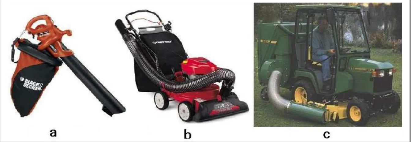
Leaf vacuum collectors that are in horticultural category machines are three types: Hand held leaf collector, Walk behind leaf collector and Tractor mounted leaf collector [2, 4, 10]. Figure.1 shows all types of the machine.
Fig. 1: All types of the Leaf vacuum collectors, a) Hand held type b) Walk behind type c) Tractor mounted
In this research, according to plant and tree kind in Isfahan gardens and most of autumn trees that are Platanus orientalis, Ulmus carpinifolia, Fraxinus excelsior, Salix alba and Morus alba,
design of vacuum section of the machine was based on properties of these leaves.
MATERIAL AND METHODS
In this research, because the main plan of machine was updated to the local area that is Isfahan, these parameters were considered: overall dimensions of the machine, vacuum mechanism of leaves and parts of vacuum section.
According to usage conditions of machine and considering the dimensions of foreign sample, overall dimensions of the machine were determined: 1500 mm length, 1000 mm height and 750 mm width [4, 5, 6].
As respects expectation of the machine operation, collection leaves from surface to a bag was selected vacuum mechanism.
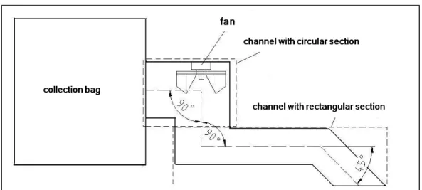
Also, according to the tasks of machine, input opening, channels and centrifugal fan were selected as components of vacuum section. Figure 2 shows schematic of leaf collection and vacuum mechanism and transferring leaves from surface to the bag of a Walk behind leaf collector.
Fig. 2: Schematic of leaf collection and vacuum mechanism of the machine Determination of dimensions of input
opening, vacuum channels
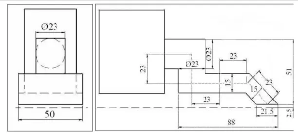
According to design of the machine, input opening, channels was considered as a completely continuous part, also as respects to design the centrifugal fan, plan of channels was considered as three bend parts, one part (45º) in
input opening and two parts (90º) in outlet. Also input opening and vacuum channels were designed with rectangular section and input opening to the fan and outlet to the bag were designed with circular section. Figure 3 shows the plan.
Selection and design of vacuum fan
Vacuum fan is the main part of the collector, so according to the foreign plan for vacuum leaves and all types of fan impellers and their applications; a centrifugal fan with radial impeller was selected for the machine [7, 18].
To obtain the dimensions of head of the fan was needed, so because of low velocity and non-compressible vacuum air, Bernoulli's equation was used between input opening and outlet points. m F
h
g
v
v
p
p
z
z
H
=
−
+
−
+
−
+
2
2 1 2 2 1 2 1 2γ
(1) HF : fan head (m)z1 and z2 : heads of input opening and outlet points (m)
p1and p2: pressure of input opening and outlet points (Pa)
v1andv2: fluid flow speed of input opening and outlet points (ms
-1
)
γ: density of the fluid (Nm-3) g: acceleration due to gravity (ms-2) hm: head of friction in junctions (m)
For determination of hm , Reynolds number
should be obtained and also flow of vacuum air. So in this research and experimental test was applied to obtain flow of vacuum air. In the test a vacuum cleaner with four adjustable gates, a pipe (with diameter equal to diameter of collector channels) connected to vacuum cleaner and digital air flow meter was used. Because wet leave on park surface have more weight that dry leaves, the testing was conducted by leaves with
35% to 45% moisture content of dry weight for five species of leaves. In the testing, the gate of air flow so was changed until the leaves were sucked to up and finally vacuum air flow obtained by digital air flow meter. Every test was repeated three times.
After determination of air flow that is needed for vacuum leaves, dimensions and Number of blades were obtained by equations (2) to (6) [7, 8] × × × = n g H d f π η 60 2 (2) 1 1 2 2d bd b = (3) 4 . 0 2 1 = d b (4) 6 . 0 2 1 = d d (5) 2 1 1 5 . 8 d d Z − = (6) d2: outside diameter of impeller (m)
HF: fan head (m)
g: acceleration due to gravity (ms-2)
η: fan efficiency
n: number of impeller rotation b1 and b2: width of impeller blade (m)
d1: inlet diameter of fan blade (m)
d2: outlet diameter of fan blade (m)
Fig. 4: Dimensions of the radial fan RESULTS AND DISCUSSION
According to the relations between in fluid mechanics, the dimensions of sections was considered as 15 and 50 cm for length and width cross section for of rectangular sections and 23
cm for the diameter of circle of circular sections [11]. Also length of channels for vacuum air was obtained according to the standard [11]. Figure 5 shows the dimensions completely.
Fig. 5: Dimensions of channels
Also, Table 1 shows the flow of air suction that estimated in each experiment, the maximum flow of air suction (1035 cubic feet per minute) for Morus alba leaves, considered in design. According to the tests and calculation and considering a safety factor with amount two for centrifugal fan with radial impeller, the fan
height was calculated as 42.2 m [7, 14]. Also according to the fan height and the relations for centrifugal fan and considering rpm as 3000 for fan impeller and efficiency as 40% for the fan, dimensions and quantity of fan impeller was Specified. Cm m d 0.2048 20.5 3000 60 4 . 0 81 . 9 2 . 42 2 = ≈ × × × =
π
Cm d1 = 0.6 × 20 .5 = 12 .3 Cm b1 = 0.4× 20 .5 = 8.2 Cm b2 =8.2×0.6 = 4.92 ≈5 22 25 . 21 6 . 0 1 5 . 8 ≈ = − = ZTable 1: The Air flow for suction leaves in three times repetition Species Air flow(ft
3/min) test No.1
Air flow(ft3/min) test No.2
Air flow(ft3/min) test No.3 Morus alba 960 1035 850 Platanus orientalis 690 820 875 Ulmus carpinifolia 550 535 640 Salix alba 320 385 340 Fraxinus excelsior 355 345 290
Also according to quality, strength, ease of access and use of conventional St37 and St44 steels in the domestic industry, these steels were selected for channels and other vacuum component.
CONCLUSION
Given the simplicity of the components considered in the design of the vacuum mechanism device for collection the leaves used in this study and convenient access to materials needed for construction and manufacturing in Iran, if the device is made, many problems REFERENCES
[1] Anonymous, 2006. A green guide to yard care, Small Business and Environmental Assistance Division, Texas Commission on Environmental Quality, Austin, and PP. 2-5.
[2] Anonymous, 2008. Lawn and tractor collection system catalogue, John Deere Company, USA, http://www.johndeere.com.
[3] Anonymous, 2002. Leaf and yard Waste composting Guidance Document, Department of Environmental Protection, Bureau of Waste Prevention, PP. 1-29.
[4] Anonymous, 2008. Self-propelled chipper shredder vacuum catalogue, USA, Troy-Bilt Company, http://www.troybilt.com.
[5] Anonymous, 2007. Self-propelled vacuum chipper shredder owner's manual, USA, Billy Goat Company, http://www.billygoat.com.
[6] Anonymous, 2005. Shredder-blower-vac catalogue, USA, Patriot Company, http://www.patriot.com.
[7] Bleier, F.P., 1998. Fan handbook, New York, McGraw-Hill Publishing Company, 1998.
[8] Bold, A. J., S. E. Kodesch and W. F. Sheehan. 1995. Combination chipper/shredder and vacuum apparatus for lawns and gardens, US Patent Office, Patent No. 5, 381, 970.
[9] Ford, S. N., 1994. Combination chipper and shredder apparatus and lawn vacuum machine. US Patent Office, Patent No.5, 340,035.
[10] Hammett, J. D. and R. W. Trevino. 1998. Portable lawn and garden mulching vacuum. US Patent Office, Patent No.5, 794,864.
[11] Irving. H. Shames, 1962. Mechanics of Fluids. McGraw-Hill.
[12] Leholm, A., 1998. Mulching tree leaves into lawns, Department of Horticulture, Michigan State University, E. Lansing, MI 48824, PP. 1-2.
[13] McLaurin, W. J. and G. L.Wade. 2000. Composting and mulching, College of Agricultural and Environmental Sciences, University of Georgia, Circular 816, PP. 1-8.
[14] Mills, D. 1989. Pneumatic conveying design guide, London, Butterworths Publishing Company.
[15] Ruhl, W. F., A.W. Nelson and J.J. Lucy. 1976. System for handling debris. US Patent Office, Patent No.3, 968,938.
[16] Somerlot, K. 2005. Composting autumn leaves, Cornell Cooperative Extension of Onondaga County.
[17] Williams, D. J. 2005. Leaf disposal, Cooperative Extension Service, Department of Natural Resources and Environmental Sciences, College of Agricultural, University of Illinois at Urbana-Champaign, NRES-18, PP. 1-3.
[18] Yaha, S. M. 2003. Turbines compressors and fans, Second Edition, New Delhi, McGraw-Hill Publishing.