APEX Task IV Summary Report for 2001
Team: C. Wong, H. Shatoff, General Atomics, S. Malang, FZK, Germany, M. Sawan, M.H. Anderson, M.L. Corradini, H. Khater, E.A. Mogahed, J.G. Murphy, I.N. Sviatoslavsky, University of Wisconsin-Madison, B. Merrill, INEEL, S. Majumdar, ANL.
APEX Task IV-Part I: EVOLVE MHD boiling experiments Authors:
M.H. Anderson, M.L. Corradini, J.G. Murphy, M. Sawan University of Wisconsin-Madison
The EVOLVE concept uses vaporized lithium to cool the first wall and blanket of a tokamak reactor. A critical issue for the EVOLVE concept is the MHD effects, with a magnetic field strength of 6-7T, on the boiling heat transfer of lithium [1]. An experimental campaign has begun to investigate the MHD effects and to characterize the vaporizing flow regime in liquid lithium.
An experimental test section of internal dimensions of 7.62cm long by 2.54cm deep and 5.08 cm tall was constructed with three 1.5mm gas injection ports equally spaced in the length of 7.62cm creating three vapor channel cells. Initial experiments were conducted with gas injection into water to calibrate and setup an X-ray absorption imaging system capable of visualizing the flow regime and determining the void fraction distribution in the pool. These initial experiments were conducted at superficial velocities an order of magnitude below that calculated for the EVOLVE situation resulted in substantial water “carry over” (water droplets were carried with the gas out of the test section). After calibration and tuning of the X-ray diagnostic imaging system a NaK handling facility was constructed to allow the transport of the NaK eutectic to the test section (this was done in a oxygen and water vapor free system). Initial experiments have been conducted with NaK and the vapor distribution with no magnetic field has been determined for a single injection nozzle of both He and N2 gas. During these experiments it was observed that the gas bubbles also entrained liquid, however since the surface tension was much higher in the liquid metal there was much less carry over. It was also observed that as the individual bubbles broke the surface of the liquid metal there was some ejection of the liquid metal into the gas space above the liquid metal pool. As the volumetric gas flow rates were increased to about a factor of 10 below that calculated for vapor production in the EVOLVE concept the pool became quite violent. Further analysis of these experiments is under way but it appears, as there may have been some slight oxidation at the surface of the NaK pool resulting in a crust formation. Improvements on the NaK handle facility have been implemented to control the level of O2and vapor down to ~5ppm while the transfer is occurring and during gas injection.
A liquid helium cryostat has been constructed that houses an AMI superconducting magnet capable of a central field of ~6T. The test section was designed to fit in a room temperature horizontal bore of this cryostat and magnet. Setup of the test section with the magnet is underway along with setup of the auxiliary monitoring and power supply systems necessary to run the magnet. We will continue this experiment to study the MHD effects on the movement of vapor bubbles in a liquid metal pool in CY2002.
[1] Anderson, M.H. et al., “EVOLVE Lithium Tray Thermal-Hydraulic Analysis,” Fusion Technology Vol. 39, March 2001, 810-814.
APEX Task IV-Part II Assessment of SiCf/SiC-LiPb FW/Blanket Concept
Authors:
The Task IV team. 1. Introduction
The mission of APEX is to explore the limits of first wall (FW) and blanket technology in order to identify concepts with a high potential for use in attractive commercial power plants. For the area of solid first wall design in FY2001 the APEX-team decided to evaluate the use of eutectic lead-lithium alloy (17Li-83Pb) as the tritium breeder and SiCf/SiC-composite as the structural material. Such a concept had been investigated by the ARIES-AT study and promises about the same thermal efficiency as EVOLVE but with reduced wall load capabilities. In FY2001 we started with the objective of determining the potential and the limitations for this class of blankets in regard to neutron wall load, surface heat flux, thermal efficiency, and reliability. We also wanted to address the impacts of the large uncertainties in the material properties: thermal conductivity under neutron irradiation, allowable stresses in the composite, and chemical compatibility between SiCf/SiC and 17Li-83Pb, while looking for the allowable neutron fluence limit. This should lead to "design windows", showing the relationship between thermal conductivity, coolant velocity and pressure drop, allowable temperatures and stresses on one side, and the resulting load capabilities and the achievable thermal efficiency on the other side. After getting into the evaluation, due to the lack of fusion neutron irradiated data, and the early development and therefore potential improvement of SiCf/SiC material, we ran into the difficulties of quantifying the credible range of thermal conductivity and other mechanical properties of SiCf/SiC composite, especially under high neutron fluence. We therefore decided to complete our evaluation in one year and reduce our objectives by assessing and reporting on the following tasks: 1. heat transfer evaluation with more detailed inputs on MHD flow and power density distribution, 2. perform further neutronics assessment with inclusion of radiation damage parameters in SiCf/SiC composite structure, 3. re-evaluate impacts related to activation and safety analysis, 4 consider the modeling of mechanical and thermal properties of the SiCf/SiC composite, and 5 report on the compatibility between 17Li-83Pb and SiCf/SiC composite. Whenever possible, we evaluated the performance impacts from the higher APEX maximum neutron wall loading goal of 10 MW/m2. Results of these tasks are summarized in the following.
2. Design Evaluation and Heat Transfer Authors:
J.G. Murphy, M.L. Corradini, and I.N. Sviatoslavsky University of Wisconsin-Madison
The ARIES-AT reference FW and blanket design was analyzed to determine the performance capability in the handling of neutron wall loading and heat loads. The design consists of two SiCf/SiC 0.5 cm walls with 17Li-83Pb flowing upward in the outside channels. There are 3 front, 8 side and 13 back sections in the upward flowing channel. The coolant (17Li-83Pb) then converges in a plenum and flows downward through the large central
channel. The design uses counter-flow configuration to remove heat from the outer channels at high fluid velocity and from the center channel at much lower fluid velocity.
The heat transfer design limit is that the walls should be maintained below≤1000˚ C. The first wall channel Hartmann flow velocity profiles in the presence of a toroidal magnetic field, were determined by UCLA and used in the finite element heat transfer model calculations. The exponentially decreasing heat generation rates were used for the central channel heat transfer calculations. By adding the Hartmann flow profiles to the analysis, the average down flowing exit temperature increased about 4 %, from 1297˚ C to 1345˚ C. By adding the spatial dependence to the down flowing heat generation rate, the average flow temperature was decreased by 1 % from 1297˚ C to 1284˚ C. Hot spots, in the coolant, were found at the inside wall. This also has an effect on the maximum wall temperature, and is essential to the heat transfer between the central and outer channels.
An iterative heat transfer analysis was performed to determine the matching heat flow rates and subsequent 17Li-83Pb temperatures between the inlet and outlet channels. For simplicity, the module walls were removed from the analysis, with all wall heat loads modeled as heat flows to the 17Li-83Pb. These heat loads show up as boundary conditions for the coolant flows in the finite element model. Because of different flow rates in the upward flowing walls and in the down flowing channel the transient heat transfer analyses had to be performed separately. These calculates were then iterated so that the local spatial heat flow entering the front wall would match the corresponding local heat flow leaving the central channel. The temperature distributions of 17Li-83Pb were then determined.
Poloidal average heat loads were taken from the ARIES-AT reference design and utilized with the UCLA velocity profiles and exponentially decreasing heat generation rate in the central channel. The first wall heat flux is a combination of the heat flow from the central channel and the volumetric heat generated in the SiCf/SiC dividing wall. It was determined that this volumetric heat generation rate was 0.08 MW/m3. Maximum SiCf/SiC wall temperatures were determined using the iterated thermal conditions for the 17Li-83Pb, with a wall (SiCf/SiC) thermal conductivity of 20 W/m-k. The final iteration yielded heat fluxes ranging from 0.483 MW/m2 at the bottom of the blanket to 0.353 MW/m2 in the middle and 0.163 MW/m2 at the top of the blanket. When the imposed heat fluxes were compared to the calculated heat fluxes (based on the thermal condition of the 17Li-83Pb) the integrated energy matched within 2 %. 17Li-83Pb that stays below a temperature of 1010˚ C surrounds the SiCf/SiC wall separating the channels. The down flowing channel reaches a maximum temperature of 1010˚ C. The up flowing channel temperature reaches 992˚ C against the central channel wall. The SiCf/SiC first wall hot spot is determined by back-calculating the temperature at the front surface of the wall, utilizing the charged particle flux as a boundary condition, the maximum temperature of the 17Li-83Pb flow upward is 1016˚ C, located at the inside of the first wall. This first wall analysis indicates that the peak temperature on top of the first wall may reach 1100˚ C facing the plasma.
This analysis assumes a poloidally uniform surface heat flux and nuclear heating. With neutron and heat flux peaking at mid-plane the maximum SiCf/SiC temperature will have to be re-calculated in the future. Maintaining the same FW/blanket geometry as ARIES-AT, we found at the neutron wall loading and surface heating removal capability will be lower than the reference values of 5 MW/m2 and 0.34 MW/m2, respectively. For design optimization, maximum temperatures could be reduced by design modifications, either by changing channel
dimensions or considering the replacement of poloidal outer flow channels with helically oriented outer flow channel configuration.
3. Neutronics and Radiation Damage Parameters in SiCf/SiC Composite Structure
Author: M. Sawan
University of Wisconsin-Madison
Neutronics calcluations were performed to determine the required blanket radial build, assess potential for achieving tritium self-sufficiency, evaluate nuclear heating profiles in the SiCf/SiC and LiPb FW/blanket design, and determine the damage parameters profiles for the SiCf/SiC composite structure. The ARIES-AT blanket design was assessed with the peak neutron wall loading doubled to 10 MW/m2. We used the ARIES-AT configuration with a 5.2 m major radius and inboard (IB) and outboard (OB) radii of 6.55 m and 3.85 m, respectively. The lithium in the LiPb breeder/coolant is enriched to 90%6Li. The ONEDANT module of the DANTSYS 3.0 discrete ordinates particle transport code system [1] was used to perform the calculations utilizing the FENDL-2 [2] data library.
The blanket is segmented to reduce radwaste stream and lower replacement cost. In ARIES-AT a replaceable blanket is used in both the IB (35 cm) and OB (30 cm) regions. A 45-cm-thick permanent blanket in the OB region and a shield in the IB region follow it. The front blanket channels are sized to ensure that the back blanket/shield zones are lifetime components. For the same lifetime criteria, the front blanket thickness should be ~7 cm thicker in APEX with twice the neutron wall loading. In APEX, the front blanket channels should be 37 and 42 cm thick in the OB and IB regions, respectively.
The local 1-D tritium breeding ratio (TBR) in ARIES-AT is 1.292 (0.353 IB, 0.939 OB). With the 7 cm thicker blanket in APEX, the local TBR is 1.344 (0.387 IB, 0.957 OB). The 3-D neutronics calculations performed for ARIES-AT (with stabilizing shells and no breeding in divertor region) showed that an overall tritium breeding ratio > 1.1 is achievable [3]. Based on ARIES-AT results, tritium self-sufficiency is not a concern for the SiCf/SiC LiPb blanket concept. Nuclear heating profiles were determined in both the LiPb and SiCf/SiC structure. Nuclear heating in LiPb is ~35% larger than in SiCf/SiC at the FW. The difference increases as one moves deeper in the blanket. Nuclear heating in SiCf/SiC drops by an order of magnitude in ~30 cm of the SiCf/SiC LiPb blanket.
The SiCf/SiC damage parameters were determined at the FW and as a function of depth in the blanket. The damage parameters calculated are the atomic displacement rate, the helium production rate, the hydrogen production rate and the total transmutation or burnup rate. The bonding for SiC is not a simple SiC molecule, but instead involves collective bond sharing among several adjacent atoms. In addition, the displacement energies are dependent on the bonding. Hence, the radiation damage parameters were calculated for both the carbon and silicon sublattices. The cross section library includes all partial reaction cross sections required to deterime gas production and transmutations. In addition, it includes the damage energy cross sections needed to determine atomic displacements. We determined the dpa cross sections using displacement energies for the Si and C sublattices of 40 and 20 eV, respectively [4]. Table 1 gives the peak radiation parameters in the Si and C sublattices. The leading interface material candidates are graphite for near-term applications, and multilayer or porous SiC for longer-range applications. Damage parameters for the SiC interface material are
identical to those for the SiC fiber and matrix. The damage parameters for the graphite interface material are the same as those for the C sublattice of SiC except for the dpa due to the higher (30 eV) displacement energy.
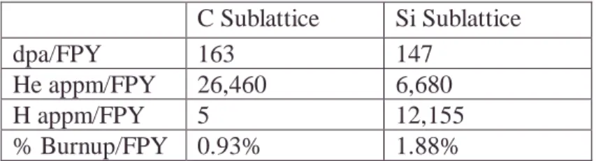
Table 1. Peak radiation parameters in the Si and C sublattices. C Sublattice Si Sublattice
dpa/FPY 163 147
He appm/FPY 26,460 6,680
H appm/FPY 5 12,155
% Burnup/FPY 0.93% 1.88%
The results indicate that the dpa rate in the C sublattice is larger than in the Si sublattice of the SiC fiber and matrix. The difference increases as one moves deeper in the blanket. The dpa rate in the graphite interface material is 33% lower than in the C sublattice of the SiC. He production rate in the C sublattice of the SiC fiber and matrix and graphite interface material is about a factor of 4 higher than in the Si sublattice of the SiC fiber and matrix. This is dominated by the (n, n´3α) reaction. The average He production rate in the graphite interface is 60% higher than the average He production rate in the SiC fiber and matrix. The He production rates drop by an order of magnitude in ~20 cm of the SiCf/SiC LiPb blanket. Significant H production occurs in Si with negligible amount in C.
The burnup rate of the Si sublattice is twice that for the C sublattice of the SiC fiber and matrix and graphite interface material. The burnup rates drop by an order of magnitude in ~20 cm of the SiCf/SiC LiPb blanket. The burnup is equivalent to introducing impurities in the sublattices of the SiC. Property degradation depends on the kind of impurities introduced. The transmutation products include Al, Mg, Li, and Be. The nonstoichiometric burnup of Si and C is expected to be worse than stoichiometric burnups and could be an important issue for the assessment of the lifetime of SiC. The results provide an essential input for SiCf/SiC composite lifetime assessment. The impact of damage parameters on SiCf/SiC composite properties and lifetime needs to be assessed by the materials community.
APEX Task IV Part II Section 3 References:
[1] R.E. Alcouffe et al., “DANTSYS 3.0, A Diffusion Accelerated Neutral Particle Transport Code System,” LA-12969-M, Los Alamos National Laboratory(June 1995). [2] M. Herman and H. Wienke, “FENDL/MG-2.0 and FENDL/MC-2.0, The Processed
Cross-Section Libraries For Neutron-Photon Transport Calculations,” Report IAEA-NDS-176, International Atomic Energy Agency (March 1997).
[3] L. El-Guebaly, “Nuclear Issues and Analysis for ARIES Spherical and Advanced Tokamaks,” Fusion Engineering and Design, 51 (2000) 325-330.
[4] S.J. Zinkle and C. Kinoshita, "Defect production in ceramics", J. Nucl. Mater. 251 (1997) 200-217.
4. Activation and Safety Analysis Authors:
B. Merrill INEEL
M. Sawan, H. Khater, E. Mogahed University of Wisconsin-Madison
We have preformed an activation and safety evaluation of the APEX solid wall ARIES-AT concept during this past fiscal year. These evaluations were performed in the context of meeting fusion specific regulatory constraints enumerated in the DOE Fusion Safety Standard [1], which are: that during a worst case accident the maximum allowable dose at the site boundary shall not exceed 10 mSv, that waste, especially high-level radioactive waste, should be minimized.
The first step in this evaluation is completing an activation analysis for this APEX design. This activation analysis was performed with the DKR-PULSAR code, using the FENDL-2 activation cross section data library, for one full-power year FPY of operation at 10 MW/m2 neutron wall loading. The input model was a one-dimensional radial build of the ARIES-AT design and the constituent material compositions used in the model are those used in Reference [2]. There are three crucial safety items obtained from these activation calculations: decay heat, radiological inventories, and radioactive waste disposal ratings. Based on these calculations and Fetter’s waste disposal ratings [3], all of the SiCf/SiC blanket structures of the solid wall concept will meet the low level waste disposal rating, with rates that are more than an order of magnitude below the allowable limit. The story is different for the LiPb coolant where the disposal rating is more that an order of magnitude above the limit due primarily to Ag-108m. This isotope will have to be removed from the LiPb before disposal.
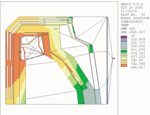
The total decay heat burden at shutdown for this concept is approximately 240 MW, due primarily to the short lived Al-28 and Si-31 isotopes. This heating quickly drops to 30 MW after six hours and to 5 MW after seven days. Two cooling accidents were analyzed to examine the impact this decay heat has on the safety of the APEX ARIES-AT design: a loss-of-coolant accident (LOCA) and a loss-of-flow accident (LOFA). Reactor temperatures were calculated with ANSYS 5.5.1 finite element code by a two-dimensional (R-Z), axi-symmetric heat conduction model of this APEX design. This model represents the upper half of the reactor, and includes axial and radial heat conduction, radiation, and convection pathways to the environment. Maximum temperatures for the inboard (IB) and outboard (OB) first wall (FW) SiCf/SiC structures are 1083 ºC and 1194 ºC respectively for the LOCA, and 1063 ºC and 1153 ºC respectively for the LOFA. All predicted temperatures were below structural limits, with the reactor cooling to below 950 ºC within one week. Figure 1 contains predicted temperatures at one week, with the maximum temperatures being produced by the tungsten divertor and stabilizer plate decay heat.
The radioactive inventories of concern are 180 g of tritium contained in the divertor and FW components (released as HTO), 10-100 kg of activated tungsten dust in the vacuum vessel (VV) from normal divertor erosion and plasma disruptions, and 5100 Ci/m3 of Hg-203 and 1380 Ci/m3 of Po-210 in the LiPb coolant. We have analyzed the response of this APEX design during two primary-confinement-barrier bypass accidents: a loss-of-vacuum accident (LOVA) and an ex-vessel LiPb coolant spill. We have chosen these accidents because based on a previous safety study [4] they produce significant environmental releases. These accidents result in a bypass of the primary radioactive confinement boundary, which is the VV. The LOVA occurs as a consequence of a failed window in a diagnostic port or plasma-heating duct. Air from a room adjoining the reactor enters the plasma chamber by way of the failed VV port, and natural convection airflow currents carry the tritium and tungsten dust within the VV to the environment by way of the ventilation ducts of the adjoining room. The ex-vessel
LOCA directly bypasses the VV by spilling LiPb coolant into the heat transfer equipment room, and mobilizing Hg-203 and Po-210 through surface evaporation. The MELCOR code was used to analyze the transport of these radioactive materials by the airflow currents to the environment as aerosol particles. The amount of tungsten dust released to the environment during the LOVA is a factor of six below the allowable limit.* To avoid releasing more than the allowable limit of HTO (15 g) isolation of the facility will have to occur within five hours, which is plenty of time even if the isolation is preformed manually. The case for the ex-vessel spill is more critical because of the location of the spill (a ventilated room), the volatility of the radioactive isotopes, and the low release limits for these isotopes. For Hg-203, the facility will have to be isolated within one hour to meet the no-evacuation dose limit, which is ample time even for manual isolation. In the case of Po-210 the facility would have to be isolated immediately (within 60 s). However, because the LiPb is a liquid coolant that is being circulated through the reactor, the opportunity exists for removing these isotopes during operation to levels that would not be a concern during this accident [5].
APEX Task IV Part II Section 4 References:
[1] DOE STD 6003-96, The Safety of Magnetic Fusion Facilities, May 1996.
[2] D. Henderson, et al., “Activation, decay heat, and waste disposal analysis for the ARIES-AT power plant,” Fusion Technology, 39, March 2001, p.444-448.
[3] S. Fetter, E. T. Cheng, F. M. Mann, “Long term radioactive waste from fusion reactors: Part II,” Fusion Engineering and Design, 13 (1990),p. 239.
[4] D. A. Petti, et al., ”Safety and environmental Assessment of ARIES-AT,” Fusion
Technology, 39, March 2001, p.449-457.
[5] S. Malang, T. Mattas, “Comparison of lithium and eutectic lead-lithium alloy, two candidate liquid metal breeder materials of self-cooled blankets,” Fusion Engineering and Design, 27 (1995), p. 399-406.
*
Figure 1. APEX ARIES-AT solid wall design temperatures during a LOCA after one week. 5. Modeling of Mechanical and Thermal Properties of the SiCf/SiC Composite
Authors:
H. Shatoff, C. Wong General Atomics S. Majumdar ANL
A SiC-burn-up of 3 % corresponding with a FW fluence of 18 MWa/m**2 has been stated in ARIES-AT design as lifetime limitation. There the blankets had been subdivided in radial direction into two zones. The inner zone has to be replaced in 4 years intervals; the outer one having a lifetime a factor 10 higher is a lifetime component. Therefore, when we consider the increase wall loading to 10 MW/m2, in order to project components lifetime it becomes important to understand further the basic neutron fluence limitation on the SiCf/SiC composite. Damage parameters can be projected by neutronics calculations as shown in section 3, but we still lack the information on the projection of irradiated SiCf/SiC thermal and mechanical properties from the calculated parameters. After reviewing the available literature, it becomes clear that fundamental modeling of SiCf/SiC properties after irradiation is necessary.
The purpose of this analysis is to study the basic fiber matrix interaction for SiCf/SiC composites under high neutron fluence. The strength, stiffness and other characteristics of the fiber/matrix material are quite complex, especially with radiation dosage effects. The ANSYS general purpose finite element code is used to model the simplest fiber/matrix situation which can be tested, e.g. the push/pull test. In the push/pull tests a block of matrix material with equally spaced and parallel fibers embedded is held while fibers are pushed or pulled out of the matrix. Displacement and force are then measured. The resultant force/displacement between fiber and matrix is dependent on material characteristics and loading. The composite is formed at temperatures above that of the ambient condition therefore there are initial thermal strain
effects between fiber and matrix before the testing. This may be enough to destroy the shear and tension strength bond between the fiber and matrix. Then all that is left is compression and the friction between fiber and matrix to produce the resistance force in the push/pull test. For the actual woven composite material the complex geometry also provides strength.
An ANSYS model of a 5˚ sector of a circular specimen push/pull test has been made (fig 1). The geometry was taken from the paper by S. Majumdar[1], An ANSYS APDL program was constructed to model and perform the analysis The ANSYS model contained both friction contact elements and bond contact elements. The bond contact elements were scanned for tension normal and shear stress levels and the calculation was terminated when the allowable stress was exceeded. The analysis is 2 dimensional though 3 dimensional finite elements were used in preparation for future 3 dimensional analyses. Results show that due to thermal strains induced by the manufacturing processes no bond strength between fiber and matrix is likely (cooled from 1350˚ C to ambient). The resistance to push/pull comes from shear friction due to thermal squeeze of the fibers. At this time linear elastic material properties were used. Bond strength data was not available and small values were assumed to reflect the full loss from thermal strain. The analytical results mimic the test data quite well within an acceptable range of assumed friction coefficients. Future work would include modeling of larger 3 dimensional composite structures with radiation and time dependent material properties.
APEX Task IV Part II Section 5 References:
[1] S. Majumdar , D. Singh and J P. Singh, “Analysis of Pushout tests on an SiCf /SiC-fiber-reinforced reaction-bonded Si3N4composite”, Composites Engineering Vol. 3 No 4, 1993.
6. Compatibility between 17Li-83Pb and SiCf/SiC-composite Author: S. Malang, FZK bond elements matrix fiber 5 deg wedge
Compatibility between 17Li-83Pb and SiCf/SiC-composite, which has impacts on the lifetime time of FW/blanket components, is a crucial issue for this class of blankets. Unfortunately, there are no experimental results available for this material combination under flowing conditions and a very limited number only investigating stagnant liquid metal in a crucible. One of these experiments were performed in 1989 in JRC-Ispra [1] and showed fairly good compatibility at 800˚ C. A second set of experiments is performed in the FZK, Karlsruhe. An isothermal test at 800˚ C with the 17Li-83Pb contained in a SiC-crucible confirmed the previous result at this temperature. A test at 1000˚C is completed but the analysis is still ongoing. Both tests were performed over a 4 weeks time period. A long term static test with a SiC/SiC-crucible has been performed at CEA (800˚C, 3000 h) which showed nearly no reaction. However, these tests with a stagnant liquid metal pool over a limited period of time are difficult to extrapolate to the conditions in a fusion blanket where the wall is exposed to flowing liquid metal over a much longer time period. Without having a suitable model describing the relevant mechanism, we do not know how we can make this extrapolation. If the concentration of Si and/or C in the liquid metal approaches saturation during the test, a linear extrapolation would under-predict material transfer. If, on the other hand, if diffusion in the wall limits the mass transfer, a linear extrapolation would over-predict mass transfer. This indicates that one should try to understand the relevant issues and the rate determining steps in order to make reasonable extrapolations. A separate point is the question, which kind of SiC should be investigated with such compatibility experiments. Here we have to keep in mind that we must in any case seal the fibers in the composite against the liquid metal for hermeticity reasons. The primary candidate material for such a layer is CVD-SiC. If this layer would fail or not be leak tight, liquid metal could enter the composite, leading to an increased electrical conductivity and finally maybe to a leak. For this reason it is probably not necessary to test the compatibility of the composite. The use of solid SiC with a similar purity as the CVD-SiC is sufficient for these compatibility tests. However, the behavior of such a leak tight seal under fusion environment will have to be assessed as stated in the above.
APEX Task IV Part II Section 6 References:
[1] V. Coen et al.,“High temperature compatibility of ceramics with the lithium lead eutectic 17Li-83Pb”, R.J. Fordham(ed.), High temperature corrosion of technical ceramics, p.69, Elsevier Applied Science, Barking, UK, 1990.
7. Conclusions and Critical Issues
In 2001, our APEX task IV team activity has two parts. The first part is the experimental study of boiling heat transfer of liquid metal in support of the EVOLVE concept. The status of this part was summarized and we should be getting the results of bubble movement of liquid metal in a magnetic field in 2002. The second part is to aim at extending the ARIES-AT SiCf/SiC composite 17Li-83Pb self-cooled FW/blanket concept to higher maximum neutron wall loading of 10 MW/m2. The ARIES-AT FW/blanket design was selected because it has the potential to be a low activation, passively safe and high thermal performance design. From neutronics calculation and safety evaluation results we found that at 10 MW/m2 neutron wall loading the tritium breeding, power loading performance; and low activation and passive safety characteristics of the design can be maintained with minor design changes. However, using the same geometry of the ARIES-AT design, with input of MHD flow distribution at the first wall channel and exponential distribution of power generation in the return flow channel, we found that the allowable maximum neutron wall loading would be lower than that specified by the ARIES-AT design at 5 MW/m2. Improvement may be possible by the optimization of the
module and channel geometries or changing the outer module poloidal channel flow to helical flow geometry. The critical issues of the design are the lack of thermal and mechanical properties of the SiCf/SiC composite at high neutron fluence and the compatibility between SiC and 17Li-83Pb at high temperature. The thermal and compatibility properties will impact the thermal performance of the design. The degradation in mechanical properties as a function of neutron fluence and compatibility will impact the lifetime of the FW/blanket components. Damage parameters for the SiC interface material, SiC fiber and matrix were calculated, but we are uncertain how these results can be translated to the irradiated design properties of the composite material. Further understanding can be obtained by the testing of these materials in fusion neutron spectrum along with close coupling with materials modeling. We have found that one of the approaches in the modeling of composite material properties could be the use of a general purpose code like ANSYS.
In order to achieve or verify the performance capability of the SiCf/SiC composite 17Li-83Pb self-cooled FW/blanket concept, we would recommend that in addition to the optimization of the design and the development of the composite material for higher irradiation resistance, leak tightness, thermal and structural performance it is important that the modeling of the fundamental properties under high neutron fluence, and compatibility experiments between SiC and 17Li-83Pb be performed in parallel.