Systematic probabilistic design methodology for simultaneously optimizing
the ship hull
e
propeller system
Ehsan Esmailian, Hassan Ghassemi
*
, Hassan Zakerdoost
Department of Maritime Engineering, Amirkabir University of Technology (AUT), Tehran, Iran
Available online▪ ▪ ▪
Abstract
The proposed design methodology represents a new approach to optimize the propellerehull system simultaneously. In this paper, two objective functions are considered, the first objective function is Lifetime Fuel Consumption (LFC) and the other one is cost function including thrust, torque, open water and skew efficiencies. The variables of the propeller geometries (Z, EAR, P/D and D) and ship hull parameters (L/B, B/T, T and CB) are considered to be optimized with cavitation, blades stress of propeller. The well-known evolutionary algorithm based on NSGA-II is employed to optimize a multi-objective problem, where the main propeller and hull dimensions are considered as design variables. The results are presented for a series 60 ship with B-series propeller. The results showed that the proposed method is an appropriate and effective approach for simultaneously propellerehull system design and is able to minimize both of the objective functions significantly.
Copyright©2016 Society of Naval Architects of Korea. Production and hosting by Elsevier B.V. This is an open access article under the CC BY-NC-ND license (http://creativecommons.org/licenses/by-nc-nd/4.0/).
Keywords:Multi-objective optimization (MOP); Hullepropeller system; Minimizing LFC
1. Introduction
Optimization of ship hullepropeller system is one of the most important aspects of ship design and leads to ship cost reduction, improving performance and increasing propulsion system lifetime. For a comprehensive and detailed ship hydro-dynamic optimization all objective functions influencing prob-lem solving need to be considered, because it is clear that consideration of an objective function without the other ones gives unrealistic and impractical results. In addition to the pa-rameters that usually are considered in the propeller design and optimization, the skew can be used as other important parame-ters in the propeller design. This parameter affects cavitation and propeller efficiency. Most of the work that has been done in the design and optimization of hull and propeller problem has been optimized only propeller or hull form with respect to
design objectives separately and less work has been carried out in the field of hullepropeller optimization simultaneously.
A method based on linear thin-ship theory to calculate the wave wake generated by a ship presented byDay and Doctors (1997). They used the elemental tent functions as building blocks to represent the hull.Dejhalla et al. (2002)proposed a genetic algorithm-based optimization method for an optimi-zation of a ship hull from a hydrodynamic point of view. In the optimization procedure, the wave resistance has been selected as an objective function. The genetic algorithm is coupled with the well-known Dawson panel method for solving the potential flow around a ship hull. A hull form optimization procedure for comparing the build cost and LFC developed by Temple and Collette (2012). Grigoropoulos and Chalkias (2010)
selected a MOP scheme for the hull form optimization with respect to its performance in calm and rough water. The nu-merical method proposed by Zakerdoost et al. (2013) for optimizing hull form in calm water with respect to the total resistance. The corrected linearized thin-ship theory is employed to estimate the wave resistance and the Evolution Strategy (ES) which is a member of the Evolutionary
*Corresponding author.
E-mail address:[email protected](H. Ghassemi).
Peer review under responsibility of Society of Naval Architects of Korea.
ScienceDirect
Publishing Services by ElsevierInternational Journal of Naval Architecture and Ocean Engineering xx (2016) 1e10
http://www.journals.elsevier.com/international-journal-of-naval-architecture-and-ocean-engineering/
http://dx.doi.org/10.1016/j.ijnaoe.2016.06.007
2092-6782/Copyright©2016 Society of Naval Architects of Korea. Production and hosting by Elsevier B.V. This is an open access article under the CC BY-NC-ND license (http://creativecommons.org/licenses/by-nc-nd/4.0/).
Algorithms (EAs) family to minimize the total resistance of Series 60 hull form by considering some design constraints. In addition, Choi (2015) developed a bell-shaped modification function in order to efficiently modify the hull-form of the ship along with the minimum wave-making resistance.Park et al. (2015) developed optimization techniques in order to opti-mize the hull form of KSUEZMAX to achieve the minimum values of wave-making and viscous pressure resistance co-efficients for the bow and stern at the full-load draft and design speed conditions.
The ship hull hydrostatics coefficients can be considered as constraints in optimization process.Yang et al. (2007)described a preliminary ship design method using deterministic and probabilistic approach in the process of hull form design with considering hull hydrostatics coefficients such as block, midship coefficients as constraints in optimization algorithm.
In the field of ship propeller optimization, Benini (2003), Lee and Lin (2004) performed a ship propeller optimization to maximize the B-series propeller efficiency by utilizing the genetic algorithm. A numerical optimization technique was developed byCho and Lee (1998)to determine the optimum propeller blade shape for efficiency improvement. A self-twisting propeller was optimized by Plucinski et al. (2007), using a genetic algorithm. They considered the orientation angles of the fibers in each layer as the design variables of efficiency improvement for an optimum design. Chen and Shih (2007) designed an optimum propeller by considering the vibration and efficiency as objective functions and cavi-tation, strength and power as constraints in B-series propeller using Genetic Algorithm. A design method for increasing performance of the marine propellers including the Wide Chord Tip (WCT) propeller is suggested byLee et al. (2010).
Gaafary et al. (2011)developed a design optimization method for B-series marine propellers with a similar objective as previous work at a single speed. A multi-objective propeller optimization program was implemented by Xie (2011) to simultaneously maximize propeller efficiency and thrust co-efficient at a single design speed. The well-known NSGA-II was used to approximate Pareto solutions of B-series pro-peller optimization.Kamarlouei et al. (2014)proposed a nu-merical method to evaluate the hydrodynamic performances including minimum cavitation, highest efficiency and acceptable blade strength. The ES technique was used as an optimization algorithm and main structural parameters as design variables to optimize the well-known B-series and DTRC propellers at design speed of typical ships. Mirjalili et al. (2015)employed Multi-objective Particle Swarm Opti-mization (MOPSO) to maximize efficiency and to minimize cavitation of marine propellers simultaneously. They utilized shape and number of blades and operating conditions (RPM) as design variables.
In the recent years, some research was done on reducing LFC. Motley et al. (2012) considered the propeller, prime mover, and vessel as one integrated system and employed the probabilistic operational profile of the vessel to minimize LFC. They evaluated the tradeoffs between different design objectives and constraints by considering the system
performance characteristics along with probability of occur-rence, and hence allows for global optimization of the pro-peller geometry. Nelson et al. (2013) presents a method to optimize the propellerehull system simultaneously in order to design a vessel to have minimal fuel consumption he optimi-zation uses a probabilistic mission profile, propellerehull interaction, and engine information to determine the coupled container ship and B-series propeller system with minimum fuel cost over its operational life.
This paper concentrates on multi-objective evolutionary optimization of the coupled propeller and hull system of a vessel using the well-known NSGA-II. Two main objectives were considered: total LFC of a vessel and linear combination of propeller open water and skew efficiencies, thrust and torque as cost objective function. The ultimate objective is to design a hullepropeller system with minimum LFC and cost that con-siders cavitation and blades stress of propeller as constraints. The main dimensions and ratios of the hull and propeller are considered as the design variables in order to achieve a globally optimum solution. The coupled series 60 hull form and B-series marine propeller employed as an initial system model. Section2
discusses the problem theory and governing mathematical formulation for calculating resistance, propeller characteristics, and fuel consumption. In Section 3, an explanation of MOP problem especially the NSGA-II is presented. The results and discussion are then provided in Section4. Finally, Section5is given as the conclusions.
2. Methodology and general formulation
2.1. Resistance calculations
When the ship is moving in the calm water, the shear force and pressure force may be applied against it. The total resis-tance is made up of two components: the viscous resisresis-tance, due to moving the ship through a viscous fluid and the wave resistance, due to moving the ship on the surface of the water. The wave resistance resulted from energy dissipation in the formation of waves on the water surface. The total resistance coefficient is:
CT¼CFð1þkÞ þCw ð1Þ
whereCFandCware the is the frictional resistance and
wave-making resistance coefficients, respectively. k is the form factor which is determined by
k¼0:6pDffiffiffiffiffiffiffiffiffiffiffiffiffi=rL3þ9D=rL3; ð2Þ
whereDis displacement,Lis the length of the ship andris the density of water.
The frictional resistance coefficient is calculated by ITTC’57 as follows
CF¼
0:075
½LogRn2
2; ð3Þ
When the ship moves in surface of water, waves are generated at the fore and stern due to the high pressure. These waves are caused to make resistance, i.e. so called wave-making resistance. There are some theories to determine the wave-making resistance like Michell's theory. Based on this theory, the equation for the wave resistance is expressed as
8 > > > > > < > > > > > : Rw¼ p 2rU 2 Zp=2 p=2 jAðqÞj2cos3ðqÞdq Cw¼ Rw 0:5rU2S w ð4Þ
ris the density of water,qis the angle between the direction of the moving ship with speed U and that of a propagating wave and A(q) is the amplitude function specific to hull shape, sometimes also called the free wave spectrum and describes the far field ship waves. More detail of this method can be found inTuck et al. (2002).
2.2. Propeller calculations
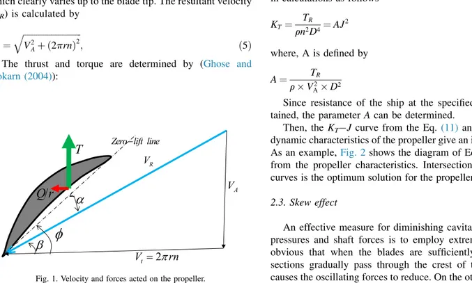
Propeller is a lifting body and lift is dominant relative to the drag. There are circulation theory and Blade Element Theory (BET) for the propeller performance calculations. BET is more efficient and the better results can be found. The blade is divided into many sections in the radial and each section is assumed as hydrofoil. If the lift and drag co-efficients at the each section is obtained, then thrust and torque can be determined.Fig. 1is demonstrated the velocity and forces diagram based on the BET. At radius r, the resultant velocity was considered to include an advance ve-locity (VA) together with a rotational (tangential) velocity (Vt)
which clearly varies up to the blade tip. The resultant velocity (VR) is calculated by VR¼ ffiffiffiffiffiffiffiffiffiffiffiffiffiffiffiffiffiffiffiffiffiffiffiffiffiffiffi V2Aþ ð2prnÞ2 q ; ð5Þ
The thrust and torque are determined by (Ghose and Gokarn (2004)): 8 > < > : T¼Z 0:5rzcV2 RðclcosðaÞ cdsinðaÞÞ dr Q¼Z 0:5rzcV2 RðclsinðaÞ cdcosðaÞÞr dr ð6Þ
where the incidence angle (a) is different angles between geometrical pitch angle (∅) and hydrodynamic pitch angle (b). The parameters ofclandcdare the lift and drag coefficients at
the blade section, respectively. r andcare the water density and the blade chord, respectively. The hydrodynamic charac-teristics of the propeller are obtained as follows:
KT¼ T rn2D4; Kq¼ Q rn2D5; ho¼ KT Kq J 2p; J¼ VA nD ð7Þ
wheren,DandJare the rotational speed of the propeller, the diameter of the propeller and the advance velocity coefficient, respectively. The advance velocity is defined as follows
VA¼Uð1wÞ ð8Þ
where w is wake fraction and is related to block coefficient (CB). It is defined by (Manen et al. (1988)):
w¼1:7643C2B1:4745CBþ0:2574 ð9Þ
The calculated thrust (TC) should be equaled or greater
than total ship resistance. The propeller thrust and therequired thrust(TR) can be calculated as follows:
TC¼KTrn2D4; TR¼
RT
ð1tÞ ð10Þ where, RT is the total ship resistance, np is the number of
propeller andtis the thrust deduction factor. Then,KTis used
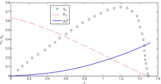
in calculations as follows KT¼ TR rn2D4¼AJ 2 ð11Þ where, A is defined by A¼ TR rV2 AD2 ð12Þ Since resistance of the ship at the specified speed is ob-tained, the parameterA can be determined.
Then, the KTJcurve from the Eq. (11)and from hydro-dynamic characteristics of the propeller give an intersect point. As an example,Fig. 2 shows the diagram of Eq.(11)andKT
from the propeller characteristics. Intersection of those two curves is the optimum solution for the propellerehull system.
2.3. Skew effect
An effective measure for diminishing cavitation, vibratory pressures and shaft forces is to employ extreme skew. It is obvious that when the blades are sufficiently skewed, the sections gradually pass through the crest of the wake thus causes the oscillating forces to reduce. On the other hand, high
2
tV
=
π
rn
AV
R VT
φ
α
/
Q r
β
Zero lift line−
skew angle could also reduce efficiency. The effect of the skew on the propeller efficiency indicates that an approximate for-mula may be obtained for efficiency in terms of the skew angle (Ghassemi, 2009):
hSkew
ho
¼0:06687e0:1148qsþ0:989e0:001029qs ð13Þ
whereqsis the skew angle in degrees andhois the open water
efficiency. According to this equation there is an inverse relationship between the skewed propeller efficiency and the skew angle.
2.4. Cavitation constraint
One of the cavitation criteria which may be used to deter-mine the expanded blade area required to avoid cavitation is based on Keller's criteria (Ghose and Gokarn (2004)). It is generally known that cavitation could affect a propeller's performance and need to be considered during the design process. A simple way to mitigate cavitation is to increase the blade area ratio. Based on the Keller criterion, expanded area ration (AE/A0) is defined as follows:
AE Ao min ¼ð1:3þ0:3zÞT ðP0PVÞD2 þK ð14Þ where AE Ao min
is the minimum blade area ratio, the coefficient
Kequals to 0.1 for twin propeller, and 0.2 for single propeller.
2.5. Propeller strength constraint
There are generally five forces acted on the blade, such as; centrifugal force (FC), thrust (T), drag force (means Q/r),
forces due to skew and rake (MRand MS),Ghose and Gokarn (2004). Due to the complex shape of the propeller blades, the accurate calculation of the stress resulting from these forces is
extremely difficult. If blade center of mass locates in radius
r¼ Z R r0 a rdr= Z R r0
rdr, the centrifugal force is calculated by:
FC¼mbrð2pnÞ
2 ð
15Þ wherembis the blade mass from radiusr0to the blade tip. So
the moments due to centrifugal force are:
MR¼Fc$zc
Ms¼Fc$yc
ð16Þ whereycandzcare the space between the centroid of the blade
and centroid of the section.MRandMsare the moments due to
rake and skew angels, respectively. So, the stress in blade section is determined by the following equation, Ghose and Gokarn (2004): S¼ Mx0 Ix0=y0 My0 Iy0 x0 þFC a0 ð17Þ where Mx0¼ ðMTþMRÞcos∅ ðMQMSÞsin∅ Mx0¼ ðMTþMRÞcos∅ ðMQMSÞsin∅ ð18Þ whereIx0andIy0are the section modulus's about thexoandyo
(axes of the centroid of the section) anda0is the area of the
section. It is obvious that the cantilever beam theory is a simple method to estimate the maximum tensile or comparison stress in any blade section. For doing the above-mentioned procedure, we first of all create a propeller geometry and then divide the blade sections into 26 stations in chord di-rection and 11 sections in radial, thereafter we do integrating by Simpson methods for calculation of the volume, mo-mentum of inertia and area for the procedure, then calculate the moments of thrust and torque and at the last step estimate the stress in blade sections (root, 0.25R and 0.3R). The amount
0 0.2 0.4 0.6 0.8 1 1.2 1.4 1.6 0 0.1 0.2 0.3 0.4 0.5 0.6 0.7 0.8 J KT , η o ηo KT AJ2
of stress achieved by this method should be less than maximum allowable stress of the propeller material.
2.6. Block coefficient constraint
The block coefficient, CB, is defined as the ratio of the
volume of displacement at a particular draft to the volume of a rectangular block with the same overall length, breadth and depth and expressed as
CB¼ V
LBT ð19Þ
whereVis displacement volume of the ship in a given draft. In the present study, the CBbetween 0.6 and 0.8 is considered as
constraint in optimization algorithm. This implies that the ship displacement is also bonded. However, one can choose appropriate hydrostatic coefficients for certain application conditions and implement it to the proposed optimization.
2.7. Lifetime fuel consumption (LFC)
The specific fuel oil consumption (SFOC) of the engine is provided by engine manufacturers as a function of engine load. In order to determine the fraction of engine load, the power requirements must be known. The effective power of the vesselPE, relates the vessel resistance and speed by
PE¼RTV ð20Þ
The resulting delivered power, PD, required of the
pro-pellers can be calculated using Eq.(21)
PD¼
PE
QPC ð21Þ
where QPC is the quasi-propulsive-coefficient given by the product of three efficiencies affecting the hull and the propeller:
QPC¼hHhRRho ð22Þ wherehHis the hull efficiency as shown in Eq.(23),hRR¼1.0
is the assumed relative rotative efficiency, andhois the open
water efficiency as calculated in Eq.(7).
hH¼
1t
1w ð23Þ
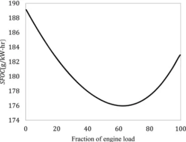
In this work, the losses due to shaft and bearing efficiencies are assumed to be negligible. Once the power is calculated the SFOC at any speed can be found based on the percentage of load. The SFOC for the L51/60DF engine as a function of engine load taken from marine engine product catalog (2009) and shown inFig. 3, is used in the current work.
2.8. Probabilistic ship speed profile
By considering the probabilistic ship speed profile along with the ship resistance and SFOC of the prime movers, per-formance comparisons can be made between different
propeller designs that consider the system performance over its design life. In order to avoid minimizing the fuel con-sumption at only a single design speed, a probabilistic approach was taken in the LFC calculation. This mission profile is highly dependent on the type of vessel being analyzed; for example, a naval combatant may have a highly bimodal distribution while one for a merchant vessel may tend to be unimodal. Using a PDF representing the operational profile of the vessel helps to avoid designing a ship that is significantly sub-optimal at off-design speeds. A probability distribution for a typical ship has been theorized in and is shown in Fig. 4.
Once the resulting PD, SFOC, and mission probabilistic
density function (PDF) are known the consumption can be found by integrating across the entire operational range.LFC
is estimated by the lifetime hours (Lh) as follows (Nelson et al. (2013)):
LFC¼
Z
PðVÞSFOCðVÞPDðVÞdV Lh ð24Þ Fig. 3. SFOC as a function of percentage of load for the L51/60DF engine.
3. Multi-objective optimization
The general mathematical form of a numerical constrained optimization problem has been represented here. Design var-iables and constraint conditions are used to characterize the problem. The role of design variables in hydrodynamic opti-mization problems is controlling the geometry of the hull during optimization procedure. Constraints are the values by which the design variables are restricted and may be separated in two types, equality and inequality constraints. A function being maximized or minimized by users is known as the objective function and the value of this function is a criterion to determine the efficiency of design optimization methodol-ogy. If in an optimization problem only one objective function is used the optimization is known as single objective and if two or more objective functions are used the optimization is known as multi objective. The standard formulation of a MOP problem mathematically is as follows:
Optimize FðXÞ ¼ ½f1ðXÞ;f2ðXÞ;…;fmðXÞ
T
X2<n
FðxÞ ¼ ½f1ðxÞ;f2ðxÞ;…;fmðxÞx2Rn
FðxÞ ¼ ½f1ðxÞ;f2ðxÞ; :::;fmðxÞx2Rn Subject to some equality and inequality constraints
hiðXÞ ¼0 i¼1;2;…;p ð25Þ
gjðXÞ 0 j¼1;2;…;q ð26Þ wherefiðXÞfiðxÞis the objective function, m is the number of objective function,qis the number of equality constraints,pis the number of inequality constraints and
X¼ ðx1;…;xnÞ2J4ℂ x¼ ðx1; :::;xnÞ2F4S is a solution or individual. The set ℂ4ℝnS4Rn defines the search space and the setJ4ℂF4S defines a feasible search space.
When we have solved the MOP, we will have found a multitude of solutions. Only a small subset of these solutions will be of interest. For a solution to be interesting there subsist a domination relation between the solution considered and other solutions in the following sense:
We say that a vectorUdominates a vectorVifUis a least as good asVfor all the objectives, andUis strictly better than
Vfor at least one objective.
ci2f1;2;…;ng;uivi∧dj2f1;2;…;ng; ujvj
Solutions which dominate the others but do not dominate themselves are called Pareto set (or non-dominated solutions) and their corresponding objective functions are called Pareto front.
3.1. Non-dominated sorting genetic algorithm-II (NSGA-II)
NSGA-II is a well-known fast and elitist multi-objective genetic algorithm that is used in this paper. The non-dominated sorting method is an important characteristic of NSGA-II. The following are the steps of the NSGA-II (Deb, 2002);
1. Initialize the population
2. While the termination criterion is not met repeat the following:
a. Evaluate each solution in the population by computing objective function values.
b. Rank the solutions in the population using non-dominated sorting.
c. Perform selection using the crowded binary tourna-ment selection operator.
d. Perform cross over and mutation (as in conventional genetic algorithm) to generate the offspring population.
e. Combine the parent and child populations.
f. Replace the parent population by the best members (selected using non-dominated sorting and the crowded comparison operator) of the combined population.
3. Output the first non-dominated front of the population
3.2. Program implementation
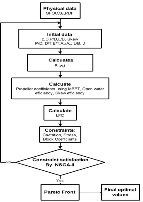
Fig. 5demonstrates how the aforementioned methods and techniques are utilized to optimize the hullepropeller system. First, by using initial values and employing the Michell's theory and ITTC-57 correction line formula the total resis-tance is calculated. The operating advance coefficient (and hence the required propeller rpm), the propeller performances and skew efficiency at this design advance coefficient are then obtained based on the known values ofRTfrom previous step
and the design variables and using BET.
If the physical constraints, the cavitation, propeller stress and block coefficient, are not satisfied, two penalty functions will be considered and added to the objective functions values. After that to consider the lifetime of the vessel in the optimization process theLFC and Cost functions, two life-time objective functions used in this work, are computed by taking into account the probabilistic mission profile of the vessel. The Cost function is a linear combination of propeller open water and skew efficiencies, thrust and torque loads as already mentioned. Finally the algorithm is repeated and once the algorithm reaches its maximum generation, the Pareto front is drawn and the final optimal solution is selected from it based on owner's or designer's conditions. Before applying the NSGA-II Algorithm we need to choice appropriate parameter settings. In this study the parameters is presented inTable 1.
The design variables and the objective functions vectors used in the optimization process are as follows as shown in
Fig. 5. The lower and upper limits of the vector are depicted in
Table 2.
X¼ ½L=B;B=T;T;EAR;Z;D;P=D;J;Skew;S FðXÞ ¼ ½LFCðXÞ;CostðXÞ
Weight amounts of thrust, torque, open water and skew efficiencies are given inTable 3. It is assumed that the skew
efficiency do not play a significant role and has lower weight in comparison with the other parameters in cost function.
4. Results and discussion
The results and analysis of the optimization run using the previously defined objective and constraint functions are pre-sented in this section. Calculations were made on a windows-based personal computer having 2.4-GHz CPUs. The required time for running this program code is about 5 h.
As a result of the evolutionary process, the NSGA-II promotes spreading of the individuals along the Pareto front, as shown in Fig. 6. The end part of generations is
utilized by the algorithm to distribute the solutions as uni-formly as possible on the front. This is a consequence of maintaining of a diverse set of solutions in the non-dominated front by using the NSGA-II. This uniform distribution is more
Fig. 5. Flowchart of the hullepropeller optimization process.
Table 1
Parameter settings of NSGA-II Algorithm.
Value Type of parameter
550 Max generation
8 Population size
30% Rate of mutation
Random Mutation type
due to the selection mechanism of the best solution in the optimization algorithm. Choosing the preferred solution among the optimal solutions (Pareto front) depends on the owner's or designer's conditions and a decision making skill is
applied to find it. We select the solution that is as close as possible to utopia point and is called compromise solution as shown inFig. 6. First the objective functions are normalized and the distance between each solution on the Pareto front and the utopia point is measured. Eventually the solution having minimum distance is chosen as the compromise solution.
The results confirm that there is an apparent conflict be-tween the LFC and cost objective function, that is, increasing in LFC will lead to decreasing in Cost and vice versa.
The initial and optimal (Pareto front) solutions are reported inTable 4. The compromise point inFig. 6 is equivalent to optimal value 5 inTable 4. As can be seen in this table the design variables of the ship hull i.e. L/B, B/T and T are the same for all optimal solutions and this indicates that difference of the optimal points is more influenced by the propeller characteristics.
It should be noted in order to assurance the optimization constraints will be satisfied, the large penalty function has been considered and therefore the large initial cost value is shown inTable 4.
Increasing the pitch ratio leads to increasing the propeller thrust and torque and thus the probability of the occurrence of the cavitation phenomenon increases. Therefore, this amount should be optimized so that produces enough thrust while pre-venting the cavitation phenomenon. Considering that all optimal solutions satisfy the cavitation constraint, the pitch ratio value 0.94 can be an appropriate value for the selected propeller. It is known that skew causes to eliminate dynamic load on the blade, reduce the fatigue and improve the propeller time endurance (lifetime). So, the selection of optimum value for the skew angle is an important issue. The optimal values of the skew angle for the Pareto front change in the small interval, 6.76e28.33, which are reasonable values for the B-series propeller.
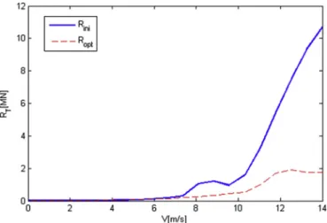
Fig. 7 shows comparison of the total resistance for the optimal hull and the initial hull within in terms of the ship speed. It can be seen that the total resistance for the optimal hull is decreased at all speed range significantly. Therefore, the optimized hull can conduct effectively in its lifetime.Table 4
confirms that however the optimal values of the parameters vary slightly relative to each other; they have considerable change relative to the corresponding initial values.
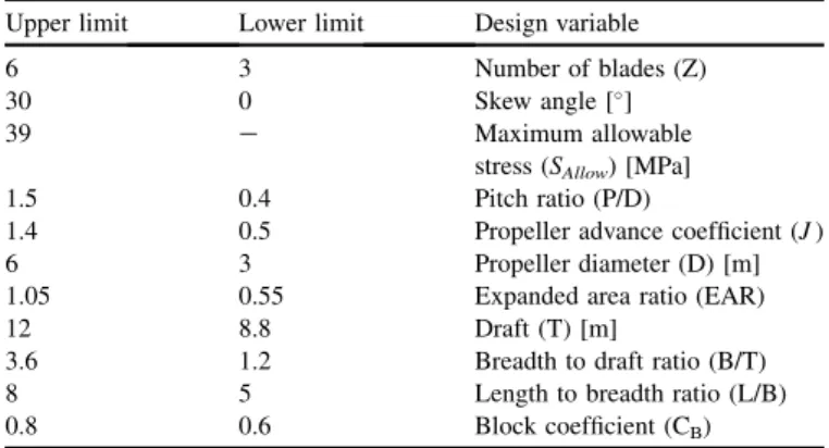
Table 2
Limits of the design variables vector.
Upper limit Lower limit Design variable
6 3 Number of blades (Z)
30 0 Skew angle []
39 e Maximum allowable
stress (SAllow) [MPa]
1.5 0.4 Pitch ratio (P/D)
1.4 0.5 Propeller advance coefficient (J)
6 3 Propeller diameter (D) [m]
1.05 0.55 Expanded area ratio (EAR)
12 8.8 Draft (T) [m]
3.6 1.2 Breadth to draft ratio (B/T)
8 5 Length to breadth ratio (L/B)
0.8 0.6 Block coefficient (CB)
Table 3
The performance weights in cost function.
Skew efficiency Efficiency Torque Thrust Performance
0.1 0.3 0.3 0.3 Weight
Fig. 6. The Pareto front, utopia and compromise solutions.
Table 4
The initial and optimal solutions (Pareto front).
Parameter Initial value Opt. value 1 Opt. value 2 Opt. value 3 Opt. value 4 Opt. value 5 Opt. value 6 Opt. value 7
L/B 5.2 7.81 7.70 6.42 5.26 7.18 5.19 5.37 B/T 1.57 2.28 1.45 3.18 3.30 2.84 3.10 1.62 T 10.59 9.29 10.95 11.99 8.87 9.83 10.23 10.92 EAR 0.97 0.69 0.85 0.71 0.63 0.96 0.66 0.60 Z 6.00 3.00 5.00 4.00 6.00 6.00 5.00 5.00 D 5.78 4.97 4.68 5.05 5.07 4.30 5.17 4.37 p D 1.28 0.50 0.65 0.76 0.94 0.55 0.62 0.96 J 0.74 1.15 0.50 1.07 1.28 0.92 1.29 0.65 Skew 21.68 10.83 15.81 17.76 8.38 28.33 12.63 6.76
LFC 7.42E11 7.25Eþ10 7.25Eþ10 7.2Eþ10 7.23Eþ10 7.23Eþ10 7.2Eþ10 7.23Eþ10
The open water performance of the initial and optimal (compromise) solutions is depicted inFig. 8. The propeller ef-ficiency in the majority of the advance coefficients while the torque and thrust coefficients are reduced. Fig. 9 shows the required thrust in terms of the ship speed. The required thrust according to Eq.(26)the required thrust is linear function of the total resistance. This is clear by comparing the total resistance and the required thrust inFigs. 7 and 9respectively.
We get closer to the best solution when the propeller torque decreases while maintaining the thrust constant. The torque variation at different speeds is shown inFig. 10. It can be seen from this figure that the propeller torque is significantly reduced compared to the initial one with increasing the ship speed.
Considering the probabilistic speed profile of the vessel (Fig. 4), V¼12.35 m/s is assumed as the ship design speed for comparing the main characteristics of the hullepropeller system. The percent of the characteristics variations at the design speed is reported inTable 5.
As can be observed the total resistance and torque of the optimal solution is improved remarkably compared to initial
solution. The open water and skew efficiencies are also improved slightly whereas the thrust is decreased as this is confirmed in Figs. 8 and 9. It is worth noting here that the amount of the torque reduction is more than that of thrust and the open water and skew efficiencies are also increased, therefore the amount of both the objective functions are improved. This is approved by comparing the initial and op-timum solutions inTable 5.
5. Conclusions
This paper has outlined a systematic probabilistic design methodology for simultaneously optimizing the ship
hull-epropeller system. The objectives of the optimization process were to minimize a two objective function, LFC and cost.
Fig. 7. The total resistance of the initial and optimal vessels.
Fig. 8. The open water performance of the initial and optimal propellers.
Fig. 9. The required thrust of the initial and optimal vessels.
Fig. 10. The propeller torque of the initial and optimal vessels.
Table 5
Variation percent of the main characteristics of the hullepropeller system.
hSkew ho Q T RT Characteristic
0.402978 0.414295 9343.955 8324.129 7053.523 Initial solution 0.620716 0.624611 2894.541 2445.149 2035.474 Optimal solution 54.0321 50.7648 69.02231 70.62576 71.14245 Variation percent
NSGA-II is first employed to estimate the Pareto front, and then a decision making skill is applied to find the best solution among them. It is apparent from this study that the technique proposed here has high capability and is appropriate for pre-liminary design of ship hull and propeller. Based on the nu-merical results, following conclusions can be drawn:
From the results, it is concluded that the main character-istics of the integrated hull- The results have demonstrated that NSGA-II, which can find Pareto front solutions with good diversity and convergence, is an efficient approach to solve the multi-objective optimization problems such as the design problem of the ship-propeller propeller system have been improved except the required thrust and in general the LFC and cost functions have been minimized significantly.
The effect of skew angle is important on the hydrody-namic characteristics and is a new operating parameter to estimate propeller efficiency in this investigation.
One of the key factors for approximating total ship cost is the LFC, thus improving the propeller and a hull perfor-mance which minimizes the LFC function could have a significant impact on reducing the lifetime cost of the vessel.
References
Benini, E., 2003. Multiobjective design optimization of B-screw series pro-pellers using evolutionary algorithms. Mar. Technol. 40 (4), 229e238. Chen, J.-H., Shih, Y.-S., 2007. Basic design of a series propeller with vibration
consideration by genetic algorithm. J. Mar. Sci. Technol. 12 (3), 119e129. Cho, J., Lee, S.-C., 1998. Propeller blade shape optimization for efficiency
improvement. Comput. Fluids 27 (3), 407e419.
Choi, H.J., 2015. Hull-form optimization of a container ship based on bell-shaped modification function. Int. J. Nav. Archit. Ocean. Eng. 7 (3), 478e489.
Day, A.H., Doctors, L.J., 1997. Resistance optimization of displacement vessels on the basis of principal parameters. J. Ship Res. 41 (4), 249e259.
Deb, K., 2002. A fast and elitist multiobjective genetic algorithm: NSGA-II. IEEE Trans. Evol. Comput. 6 (2), 182e197.
Dejhalla, R., Mrsa, Z., Vukovic, S., 2002. A genetic algorithm approach to the problem of minimum ship wave resistance. Mar. Technol. 39 (3), 187e195.
Gaafary, M., El-Kilani, H., Moustafa, M., 2011. Optimum design of B-series marine propellers. Alex. Eng. J. 50 (1), 13e18.
Ghassemi, H., 2009. The effect of wake flow and skew angle on the ship propeller performance. Sci. Iran. 16 (2), 149e158.
Ghose, J.P., Gokarn, R.P., 2004. Basic Ship Propulsion. Allied Publishers. Grigoropoulos, G.J., Chalkias, D.S., 2010. Hull-form optimization in calm and
rough water. Comput.Aided Des. 42 (11), 977e984.
Kamarlouei, M., Ghassemi, H., Aslansefat, Nematy, D., 2014. Multi-objective evolutionary optimization technique applied to propeller design. Acta Polytech. Hung. 11 (9).
Lee, C.-S., Choi, Y.-D., Ahn, B.-K., Shin, M.-S., Jang, H.-G., 2010. Perfor-mance optimization of marine propellers. Int. J. Nav. Archit. Ocean. Eng. 2 (4), 211e216.
Lee, Y.-J., Lin, C.-C., 2004. Optimized design of composite propeller. Mech. Adv. Mater. Struct. 11 (1), 17e30.
Mirjalili, S., Lewis, A., Mirjalili, S.A.M., 2015. Multi-objective optimisation of marine propellers. Procedia Comput. Sci. 51, 2247e2256.
Motley, M.R., Nelson, M., Young, Y.L., 2012. Integrated probabilistic design of marine propulsors to minimize lifetime fuel consumption. Ocean. Eng. 45, 1e8.
Nelson, M., Temple, D.W., Hwang, J.T., Young, Y.L., Martines, J.R.R.A., Collette, M., 2013. Simultaneous optimization of propellerehull systems to minimize lifetime fuel consumption. Appl. Ocean Res. 43, 46e52. Park, H., Choi, J.E., Chun, H.H., 2015. Hull-form optimization of
KSUEZ-MAX to enhance resistance performance. Int. J. Nav. Archit. Ocean. Eng. 7 (1), 100e114.
Plucinski, M.M., Young, Y.L., Liu, Z., 2007. Optimization of a self-twisting composite marine propeller using genetic algorithms. In: 16th Interna-tional Conference on Composite Materials, Kyoto, Japan.
Temple, D., Collette, M., 2012. Multi-objective hull form optimization to compare build cost and lifetime fuel consumption. In: International Ma-rine Design Conference, IMDC, Glasgow, Scotland, 11-14 06, II, pp. 391e403.
Tuck, E., Scullen, D., Lazauskas, L., 2002. Wave patterns and minimum wave resistance for high-speed vessels. In: 24th Symposium on Naval Hydro-dynamics, Fukuoka, Japan.
Xie, G., 2011. Optimal preliminary propeller design based on multi-objective optimization approach. Procedia Eng. 16, 278e283.
Yang, Y.S., Park, C.K., Lee, K.H., Suh, J.C., 2007. A study on the preliminary ship design method using deterministic approach and probabilistic approach including hull form. Struct. Multidiscip. Optim. 33 (6), 529e539.
Zakerdoost, H., Ghassemi, H., Ghiasi, M., 2013. Ship hull form optimization by evolutionary algorithm in order to diminish the resistance. J. Mar. Sci. Appl. 12 (2), 170e179.