Entebbe October 2001
Data Retrieval, Processing and
Final Storage into the Nile Basin Database
Manual
The designations employed and the presentation of material throughout this book do not imply the expression of any opinion whatsoever on the part of the Food and Agriculture Organization (FAO) concerning the legal or development status of any country, territory, city, or area or of its authorities, or concerning the delimitations of its frontiers or boundaries.
The authors are responsible for the choice and the presentation of the facts contained in this book and for the opinions expressed therein, which are not necessarily those of FAO and do not commit the Organization.
Table of Contents
Table of Contents
1
Introduction
9
1.1
General
9
1.2
Overview of the Contents of the Manual
9
2
Detailed Outline of the Data Trajectory
11
2.1
General
11
2.2
Hardware
11
2.3
Software
12
2.4
Comprehensive Data Trajectory
13
3
Installation of the Remaining Hardware and Software
15
3.1
Installation of SC532-A Interface
15
3.2
Installation of PC208W Datalogger Support Software
15
4
Recommended Folder (Directory) Structure
16
4.1
General
16
4.2
PC208W Files
16
4.3
MS Access Database Files
17
5
PC208W Datalogger Support Software
19
5.1
Introduction
19
5.2
StgModule Component
19
5.2.1 Introduction
5.2.2 Connecting Storage Module to PC
5.2.3 Retrieving Raw Data Files from Storage Module 5.2.4 Pointers
5.2.5 Erasing Data on the Storage Module 5.2.6 Trouble Shooting
5.3.2 Processing Data from Met Station 5.3.2.1 General
5.3.2.2 Five-Minute Rainfall Data
5.3.2.3 Hourly Meteorological Time Series 5.3.2.4 Daily Meteorological Time Series
5.3.2.5 Meteorological Station Performance Information 5.3.2.6 Renaming Meteorological Output Files
6
Data Processing in MS Access and Final Storage into the NBD
39
6.1
General
39
6.2
MS Access Database “NBD NEW DATA”
39
6.3
Importing Output ASCII Text Files Generated by Report into MS Access
41
6.4
Processing of Imported Data in MS Access and Final Transfer into the NBD
47
6.5
Transfer of Raw Input and Report Output Files into Backup Folder
51
7
Exchange of NBD Data with Other Users
52
7.1
Problem Description
52
7.2
Preparation of Transfer Files
52
Figure 1: Hardware components involved in data acquisition process 11 Figure 2: Software components and file formats involved in data acquisition
and storage process 12
Figure 3: Recommended directory structure for PC208W and related “work” files 16 Figure 4: Required Folder (Directory) structure for all MS Access database files 17 Figure 5: Final data processing steps in MS Access and subsequent removal and
storage of raw files as backups 39
List of Figures
List of Figures
List of Tables
Table 1: Comprehensive Data Trajectory 14
Table 2: Various Files and their Function Used by Report in the Processing of
Meteo Station Measurements 27
Table 3: Database Objects and their Function in the MS Access Database file
”NBD_Pre Processing.mdb” 40
Table 4: Designated Input and Destination Tables for each Pre-defined Append Query 48
Annexes
Annexes
Annex 1: Consecutive Steps in Connecting Storage Module SM4M/SM192 to PC.
Annex 2: Consecutive Steps in Retrieving Raw Data Files form SM4M/SM192 Storage Module to PC. Annex 3: Consecutive Steps in Processing Raw Data Files in Report.
Annex 4: Consecutive Steps in Pre-Processing of Report Output Files in MS Access and Appending Processed New Data Sets into NBD.
Annex 5: General Design of the Append Queries for Pre-Processing of the Report Output Files in MS Access. Annex 6: Design of the ID Converter Table.
FAO regional project GCP/INT/752/ITA – Nile Basin Water Resources is committed in establishing a limited water resources monitoring network in the Nile Basin region. The adopted monitoring network consists of 21 meteorological and 14 hydrological stations to be either rehabilitated or newly implemented at key points in the Nile Basin. These stations will be supplied with conventional and/or fully automatic equipment depending upon the priorities of the hydrometeorological departments in the respective beneficiary countries. This network is a continuation of the efforts made by the previously concluded FAO Lake Victoria Water Resources Project, which has already established, fully automatic 14 hydrological and 4 meteorological stations in the Lake Victoria region of the Nile Basin. The network is no doubt inadequate as compared to the identified needs and water resources development priorities in the region. The beneficiary countries have placed, with slight variation an emphasis and scope, a high priority on sustainable and environmentally sound water resources development in the Nile Basin region to satisfy rapidly increasing water demand for irrigation to increase food production, hydropower production and domestic and industrial water supply. For this reason, substantial additional efforts and resources will be necessary to address the remaining gaps in the environmental and water resources data and information by expanding further the monitoring network and geo-referenced database system established by the FAO Projects in the region.
Recognizing the importance of the established nucleus monitoring network in this context, the project is making every effort to secure its sustainable and technically sound operation and maintenance, as well as collection of data from the network, data quality control, processing and final storage into the Nile Basin database. To this effect most of the stations in the adopted network are being furnished with state of the art data loggers and hydrometeorological measuring sensors which require minimum efforts and material for operation and maintenance. It is important to mention that the experience gained from the automatic equipment installed by the concluded Project have been proved, now for years, to be successful. Furthermore the project is developing a series of technical manuals and conducting comprehensive on-the-job training seminars and workshops in the region on all aspects of equipment installation, station operation and maintenance and data processing.
The Manual on Data Retrieval, Processing and Final Storage into the Nile Basin Databases is the latest in the series. Its first version was written in January 99 during the previously concluded FAO GCP/RAF/304/JPN and has now been revised due to the rapidly changing technology in its hardware and software installed in the Nile Basin. The manual, at present, has also been subsequently used for training of national professionals in Rwanda, Kenya and Uganda and is expected to be used for training of national professionals in other countries. The experience gained during these practical training sessions was used to substantially simplify and improve many of the procedures in this revised version of the manual. The project is thankful to all the trainees in the region for their enthusiastic participation in the training sessions conducted so far and the extraordinary efforts in mastering the technology. Based on evaluation of skills and know-how already in place in 4 countries of the region in this field we are confident that the revised Manual presented hereby will further contribute towards the achievement of the major goal: the sustainable and technically sound operation and maintenance of the monitoring network established by the Project in the region, including the collection, quality control and processing of data generated in the network.
Dr. Mohammad Chebane Chief Technical Advisor
October 2001, Entebbe, Uganda
Foreword
Foreword1.1 General
The adopted Monitoring Network in the Nile Basin comprises of Automatic Hydrological and Meteorological Stations equipped with electronic instruments for data acquisition and storage. Measurements are initially pre-processed and stored on site in a digital storage and control module, commonly referred to as datalogger.
Periodically, the accumulated raw data are transferred from datalogger to a computer at the office of the hydro-meteorological service. This is accomplished with the help of a portable data retrieval unit, which can serve several stations during a single inspection tour. In order to enhance sustainability of the network, a visiting frequency of 1 month is proposed. Consequently, data should arrive at the office of the hydro-meteorological service with a delay of maximum one month.
After transfer of the collected hydro-meteorological information from retrieval unit to PC, the newly imported data should be processed, checked on consistency and possible measurement errors, and stored in a dedicated table in the Nile Basin Database (NBD), regarded as their final destination.
The first segment of the data trajectory, i.e. transfer of measurements form logger to retrieval unit, is covered in the manual “Manual for Installation, Operation and Maintenance of Automatic Meteorological Stations”.
The second part of the data trajectory is dealt with in this manual. It describes in detail all steps involved in transferring the accumulated climatological measurements from the storage module to PC, processing of data downloaded onto PC and final storage of the processed time series to the Nile Basin Database [NBD] in MS Access. More specifically, this manual deals with the procedures for:
installation and setup of necessary hardware components; •
transfer of raw data from storage module to PC in the initial data and file formats; •
separation of individual measured variables from initial data file to comma separated ASCII file, and first visual •
data quality check;
importing the pre-processed ASCII data file into MS Access;rearrangement of newly imported data to final •
table structure using pre-defined database queries and second computer operated quality check; appending and final storage of new data into the Nile Basin Database.
•
This manual deals with data originating from Campbell type Automatic Weather Stations (AWS). A substantial number of steps involved in the data trajectory are included in the manual for processing actions.
1.2 Overview of the Contents of the Manual
This manual describes in detail all steps and operations involved in transferring the accumulated raw data from retrieval unit to PC and primary processing – by using a Campbell Scientific software package, called PC208W, which has been specifically tailored for the purpose; and secondary processing of pre-processed data and their subsequent final storage into the NBD – by using MS Access database package.
In order to provide the user with the complete picture of the information flow from sensor to database, chapter 2 presents a detailed outline of the comprehensive data trajectory, as well as all software and hardware components involved, and their role.
Chapter 3 concentrates on the instructions for installing the necessary hardware and software components that are to be set up in appropriate manner.
Introduction
Introduction
location of the concerned files on the PC’s hard disk drive.
Chapter 5 deals in detail with retrieving the raw data from the storage module to PC, and the initial processing and storing this new information into a file in a comma separated ASCII format for each strictly defined group of data.
Chapter 6 presents the instructions for importing the pre-processed new data set into MS Access, performing a final processing round and storing the new data records into their final destination in the NBD.
Finally, chapter 7 describes the procedures for creating an MS Access “transfer” database file, extraction of needed data records from any main NBD file/table and their storage into the ‘transfer’ file; this will enable the users to disseminate the selected data records from NBD to other users, within the country of in the Nile Basin region, in an easy manner and without violating the integrity of either new or historical data stored in the main NBD.
Detailed Outline of Data Trajectory
2.1 General
This chapter gives an overview of the complete data trajectory, starting from values measured by the station’s sen-sor all the way till the final storage of data into the Nile Basin Database (NBD) on PC at the FPI. It presents the vari-ous hardware and software components involved in this process, together with their interconnection. Furthermore, it lists sequentially all user actions that play a role in the data trajectory.
2.2 Hardware
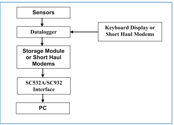
Figure 1 presents all hardware components involved in the route from sensor to PC in the hydro-meteorological data acquisition process
Detailed Outline of Data Trajectory
The various climatological parameters are measured using electronic sensors. Depending on the nature of a parameter, its value is represented by either a voltage or a sum of pulses.
The datalogger measures the voltages and/or counts the pulses, and transfers them to intelligible figures in standard units, like for example degrees Celsius for temperature or mm of rainfall for precipitation. Other tasks of the datalogger are to activate the various sensors at pre-defined intervals, and store the measurements in its memory.
The CR10KD keyboard display is used to communicate with the datalogger on site. For instance, in case when a user wants to invoke manual data transfer or check on operation of individual sensors, this is accomplished by con-necting the CR10KD keyboard to storage module and logger, and by typing in on the keyboard the proper commands. Also, when the user wants to check the performance of sensors and datalogger while onsite, this is achieved by connecting the keyboard only to the datalogger and keying in the respective commands.
Figure 1: Hardware components involved in data acquisition process.
Sensors
Datalogger
Storage Module
or Short Haul
Modems
SC532A/SC932
Interface
PC
Keyboard Display or
Short Haul Modems
Detailed Outline of Data Trajectory
thereafter to transfer/upload the raw data to the Personal Computer at the office. Information is stored in the module in a specific format, which cannot be read directly by IBM compatible PCs.
The role of the SC532A or SC932 Interface is, therefore, to convert this specific storage module format into a RS232 compatible information communication standard, which is ‘understood’ by IBM compatible PCs.
Data can also be downloaded directly from the meteorological station to the PC using short haul modems without using key-board and storage module.
Data pre-processing, processing final check and storage in the NBD is accomplished on PC.
2.3 Software
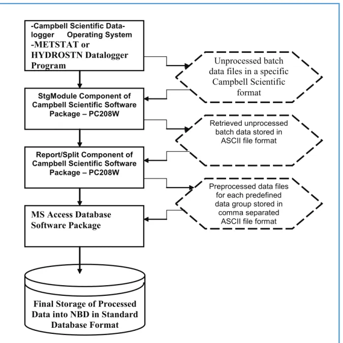
Figure 2 presents the various software packages and programs, as well as the concerned file formats, which are used in the process of data acquisition, pre-processing, processing and final storage.
Data processing, rearrangement and final storage in the LVBD is accomplished on PC.
Figure 2: Software components and file formats involved in data acquisition and storage process.
-Campbell Scientific Data- logger Operating System
-METSTAT or
HYDROSTN Datalogger
Program
StgModule Component of Campbell Scientific Software
Package – PC208W
Report/Split Component of Campbell Scientific Software
Package – PC208W
MS Access Database
Software Package
Final Storage of Processed
Data into NBD in Standard
Database Format
Unprocessed batch
data files in a specific
Campbell Scientific
format
Retrieved unprocessed batch data stored in
ASCII file format
Preprocessed data files for each predefined data group stored in
comma separated ASCII file format
Detailed Outline of Data Trajectory
The datalogger works under a specific Campbell Scientific operating system and is controlled by the METSTAT datalogger program for meteorological stations. These programs are specifically created by the project GCP/INT/752/ ITA – Nile Basin Water Resources for the sensor configuration and data requirements in the network established by the project. The datalogger program has been tested extensively by the project specialists, proved to work properly and require no further user intervention.
As indicated in paragraph 2.2, data is transferred from datalogger to PC with help of the SM4M/SM192 storage module. These modules use a specific Campbell Scientific data format, which is highly condensed in order to make optimal use of its memory.
Once the observed data are downloaded to the storage module, the next steps are performed by using PC208W Datalogger Support Software. This is a special software package developed by Campbell Scientific for communication between datalogger and PC. It consists of 8 modules of which only two are of interest for handling meteorological data measured in the network established by the project in the Nile Basin.
The StgModule component of the software retrieves files from the SM4M or SM192 Storage Module into ASCII files on PC without any modification of the original data structure and sequence stored in the storage module.
The Report component, often referred to as Split, is used to split, restructure and separate these ASCII files according to the required file/table structure of the user, transfer the dates from Julian format to corresponding months and days, and store the resulting data groups into a comma separated ASCII file. The latter format is preferred for subsequent import of external data into MS Access.
Final data processing is accomplished by using MS Access database software package through several pre-defined database tables and queries; the tables and queries have been specifically tailored for final processing of meteorological data observed in the network established by the project. Lastly, the processed data are appended and finally stored into the appropriate tables in the MS Access based Nile Basin Database.
2.4 Comprehensive Data Trajectory
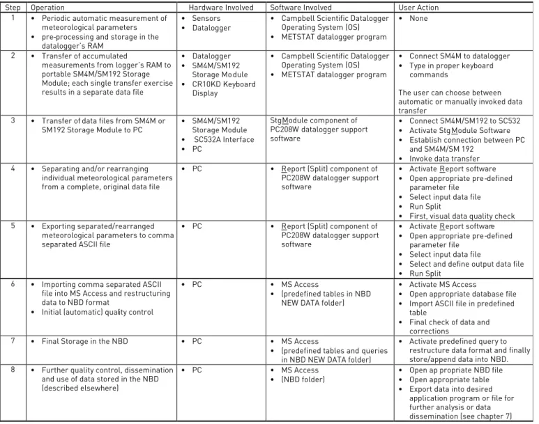
In order to arrive at a complete understanding of interconnections between the various hardware and software elements that play a role in the data flow, table 1 presents a comprehensive overview of the entire data trajectory - from initial measurement to final dissemination. It shows the place and function of the respective hardware and software items and their interrelation. Furthermore, it lists in a sequential order all necessary user actions.
All the actions described in table 1 are covered in this manual except for those indicated under the 1, 2 and 8. These three actions are included into the table for user’s benefit of having better insight into the whole data trajectory – starting from its onsite measurement by a sensor and ending up with the use of stored data for various types of water resources analysis, studies and modeling. The procedures concerned with actions 1 and 2 are covered in the respective operation and installation manuals specifically concerned with Automatic Weather Stations established within the project. The action refers to a broad range of applications in water resources analysis and modeling which are described elsewhere, including a series of training notes for data processing and analysis within the geo-referenced database as well as The Nile Basin Decision Support Tool manuals and software packages developed under the project.
Consequently, as already indicated in paragraph 1.1, this manual covers in detail the actions 3 to 7 given in table 1.
Detailed Outline of Data Trajectory
Step Operation Hardware Involved Software Involved User Action 1 ~ Periodic automatic measurement of
meteorological parameters
~ pre-processing and storage in the datalogger’s RAM
~ Sensors
~ Datalogger ~ Campbell Scientific Datalogger Operating System (OS)
~ METSTAT datalogger program
~ None 2 ~ Transfer of accumulated
measurements from logger’s RAM to portable SM4M/SM192 Storage Module; each single transfer exercise results in a separate data file
~ Datalogger
~ SM4M/SM192 Storage Module
~ CR10KD Keyboard Display
~ Campbell Scientific Datalogger Operating System (OS)
~ METSTAT datalogger program
~ Connect SM4M to datalogger
~ Type in proper keyboard commands
The user can choose between automatic or manually invoked data transfer
3 ~ Transfer of data files from SM4M or
SM192 Storage Module to PC ~ SM4M/SM192 Storage Module
~ SC532A Interface ~ PC StgModule component of PC208W datalogger support software ~ Connect SM4M/SM192 to SC532
~ Activate StgModule Software
~ Establish connection between PC and SM4M/SM 192
~ Invoke data transfer 4 ~ Separating and/or rearranging
individual meteorological parameters from a complete, original data file
~ PC ~ Report (Split) component of PC208W datalogger support software
~ Activate Report software
~ Open appropriate pre-defined parameter file
~ Select input data file
~ Run Split
~ First, visual data quality check 5 ~ Exporting separated/rearranged
meteorological parameters to comma separated ASCII file
~ PC ~ Report (Split) component of PC208W datalogger support software
~ Activate Report software
~ Open appropriate pre-defined parameter file
~ Select input data file
~ Select and define output data file
~ Run Split 6 ~ Importing comma separated ASCII
file into MS Access and restructuring data to NBD format
~ Initial (automatic) quality control
~ PC ~ MS Access
~ (predefined tables in NBD NEW DATA folder)
~ Activate MS Access
~ Open appropriate database file
~ Import ASCII file in predefined table
~ Final check of data and corrections
7 ~ Final Storage in the NBD ~ PC ~ MS Access
~ (predefined tables and queries in NBD NEW DATA folder)
~ Activate predefined query to restructure data format and finally store/append data into NBD. 8 ~ Further quality control, dissemination
and use of data stored in the NBD (described elsewhere)
~ PC ~ MS Access
~ (NBD folder) ~~ Open ap propriate NBD file Open appropriate table
~ Export data into desired application program or file for further analysis or data dissemination (see chapter 7)
3.1 Installation of SC532A Interface
Provided a PC has already been set up successfully, only one hardware item remains to be installed: the SC532A Interface. The function of this interface is to connect IBM compatible computers to the SM4M or SM192 storage module and convert their contents into RS232 format, or more precisely into a standard RS232 data transfer protocol, which is well understood by any IBM compatible personal computer.
In case the short haul modems are used for on line data collection, the SC932 Interface is connected permanently and therefore the use of SC532 Interface should be avoided.
The SC532A has a 9-pin connector for linkage with the storage module and uses a 9-pin connector to connect the interface to a 9-pin serial port at the PC. The SC532A interface is powered by an AC adapter. Both the 9-pin female connecting ends of the SC532A interface are identical therefore care should be taken that its “PC” labeled end should be connected to the serial port at the PC and that the “PERIPHERAL” labeled end is connected to the SM4M storage module.
Installation of the SC532A Interface is a straight forward process. Connect the SC532A to PC using the supplied ‘9 to 9 pin’ computer cable. The 9-pin female end of the cable should be connected to the PC’s serial port 1 or 2, while the other 9-pin male end of the cable is to be plugged into the SC532A.
Connect the other 9-pin female end of the SC532A interface to the SM4M Storage Module using the blue, specific Campbell Scientific SC12 storage module cable.
Since the SC532 Interface runs on 110V, use a 220 - 110 transformer between mains and the SC532A while in East Africa.
All hardware components are now installed. Make sure power is supplied to the SC532.
Note: The old model SC532 Interface has 25-pin connector while the other end has a 9-pin connector and therefore using a 25 to 9-pin computer cable. This information is for the users in Kenya, Uganda and Tanzania.
3.2 Installation of PC208W Datalogger Support Software
PC208W 3.3 Datalogger Support Software requires Windows 95 or higher. There needs to be at least 10Mb of free hard disk space for software installation.
Insert the PC208W CD in drive D. It will install automatically by following the instructions on the screen. Otherwise in Windows 95 (or above), select RUN from the Start button. Type in A:\SETUP and click the OK button. Follow the instructions given on the screen.
It is recommended to use the following Working Directory name: C:/CAMPBELL/PC208W.
Installation of the remaining Hardware and
Software
Recommended Directory Structure
4.1 General
For standardization and instruction purposes, this chapter proposes a Recommended Folder (Directory) Structure. The user is free to modify this if another system would better suits his or her particular computer organization. However, the instructions presented in this manual are based on the proposed structure. Modification of it will require corresponding adjustment of commands concerning file locations.
4.2 PC208W Files
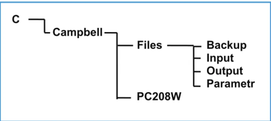
Figure 3 presents the Recommended Directory Structure for all files related to PC208W Datalogger Support Software. A subdivision has been made between the PC208W program files and the ones actually used in the data processing, the ‘work’ files.
Recommended Directory Structure
C
Campbell
Files
Backup
Input
Output
Parametr
PC208W
Figure 3: Recommended Directory Structure for PC208W and related ‘work’ files.
The above Folder (Directory Structure required the creation of a main folder called CAMPBELL on the C drive. The Campbell Folder consists of two sub-folders named FILES and PC208W. The datalogger support software PC208W should be installed in the latter one, see paragraph 3.2.
The FILES folder is sub-divided into four folders: INPUT, OUTPUT, PARAMETER and BACKUP.
The INPUT sub-folder is destined for all data files retrieved from the SM4M/SM192 storage module or directly from the datalogger using short haul modems. By default these files are given a DAT extension.
The OUTPUT sub-folder is allocated for all processed, comma separated ASCII files, with TXT extension. They result from the separation and file restructuring exercise in Report (a.k.a. Split).
The PARAMETR sub-folder is used to store all predefined Split files, having a PAR extension.
The BACKUP sub-folder is used to temporarily store the files once they have been converted and processed in MS Access. Use of the above mentioned files is discussed in more detail in chapter 5. The proposed structure is illustrated in the following Windows Explorer screen.
Recommended Directory Structure
*For the creation of the various folders, use the appropriate Windows Explorer commands.
4.3 MS Access Database Files
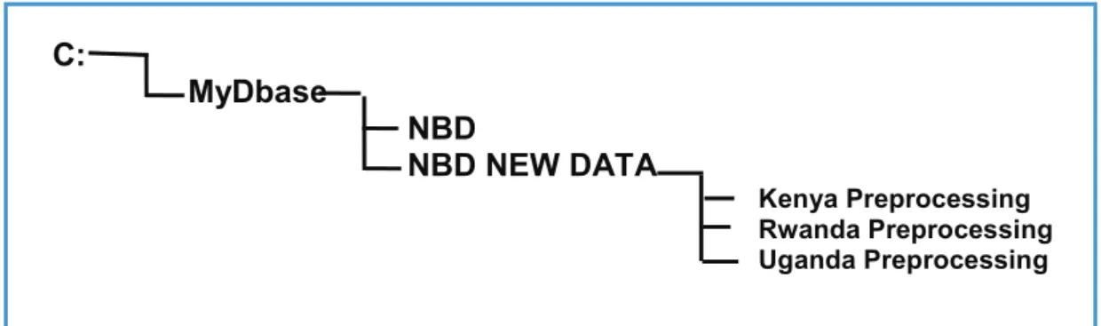
Figure 4 illustrates the required Folder (Directory) Structure for further processing of data in MS Access and final storage of processed data files into the NBD in database standard format. This format can, later on, be changed once a final structure for the Nile Basin Database has been developed.
C:
MyDbase
NBD
NBD NEW DATA
Kenya Preprocessing Rwanda Preprocessing Uganda PreprocessingFigure 4: Required Folder (Directory) Structure for all MS Access database files.
For this purpose it is required to create a main database folder called MyDbase on the C drive. This folder should consist of two sub-folders called NBD and NBD NEW DATA. The former will be used to store the Nile Basin Database files, while the latter is basically planned to contain temporary data files imported from the C:/Campbell/Files/ Output folder and append queries; the imported dta files and append queries are used for further data processing in MS Access, prior to final storage of processed data records into the NBD data tables in standard data format.
For the creation of the proposed directory structure, use the appropriate Windows Explorer commands. Once more, the structure is illustrated below as displayed on the Windows Explorer screen:
PC208W Datalogger Support Software
5.1 Introduction
PC208W Datalogger Support Software is a Windows based software package specifically developed by Campbell Scientific for communication between datalogger and PC. It consists of a help module and 7 independent datalogger support components. Among them are also the utilities for setting up a network of PC connected stations and on-line datalogger communication. Depending on the conditions and requirements these utilities will not be used in certain cases whereas in other cases these may be used wherever feasible in the Basin. For example the Project may consider the option of direct on-line communication with the stations using short haul modems or cellular mobile communications.
Smooth flow of data from datalogger to Nile Basin Database is accomplished with the help of the following three PC208W utilities: Connect, StgModule and Report. The first and second serve to transfer raw data files either directly from the datalogger to the PC via short haul modems or then from storage module to PC, while the second is used to separate the various meteorological variables from raw batch data transferred from the datalogger or storage module into PC, and re-arrange their data structure.
These software utilities will be discussed in the paragraphs given below. However, the text that follows does not cover all aspects of the two PC208W software utilities. Only the subjects which are considered important and essential in the data downloading process are discussed. The user is referred to the respective Campbell Scientific Instruction Manuals, as well as the on-line help, in case of need for more information. The use of “Connect” utility is still under experiment at the Project office and will be included in the manual later on.
5.2 StgModule Component
5.2.1 Introduction
Due to recent rapid developments in the mobile/cellular telecommunications in most of the African countries, it has become feasible to establish on-line communication between a datalogger and a PC. The Project experts are exploring ways for making it possible to transfer on-line digital data from a remotely stationed datalogger to the PC using a cellular communication facility. Apart from this, the project has also opted for the portable SM4M or SM192 Storage Module to transfer the accumulated raw data from the logger’s RAM to personal computer. This storage device can contain up to almost 400,000 data values as well as a maximum of 8 datalogger programs. Communication between storage module and PC is enabled through the StgModule software, discussed in this paragraph.
5.2.2 Connecting Storage Module to PC
This paragraph presents the instructions for establishing communication between SM4M or SM192 and PC. Step A1: Connect the SM4M/SM192 Storage Module to the SC532A Interface using the blue SC12 cable. Step A2: Make sure the SC532A Interface is powered.
Step A3: Double click the PC208W Datalogger Support Software Icon, presented below.
PC208W Datalogger Support Software
The following toolbar appears:
Step A4: Click the StgModule tab. A window alike the one presented below shows up.
The menu-bar contains five different items: File, Options, Data, Tools and Help. Just beneath this line 4 different tabs are found, named CSM1/MCR1, SM192/SM716, PCCard and SM4M/SM16M, each dealing with a different stor-age medium. Since the Nile Basin Monitoring Network is either equipped with the SM4M or SM192 unit, click the required SM192/SM716 or SM4M/SM16M tab at the top-mid of the screen to activate its specific communication software. Disregard the other three tabs.
Step A5: Click the SM4M/SM16M or SM192/SM716 tab at the top-mid of the SMS window.
The resulting window is divided into two halves: a status box on the right and a task specific sub- screen on the left.
At the bottom-left of the latter, four different tabs are found: Setup, Programs, Data and Erase.
Step A6: Click the tab labeled ‘Setup’ to select the appropriate communication settings. The below screen appears.
PC208W Datalogger Support Software
Step A7: Select the COM Port settings corresponding to the serial port used by the “9 to 9 pin” computer cable connecting the SC532A Interface (see paragraph 3.1). In most cases this will be either COM1 or COM2.
Step A8: Set Baud Rate at 19200. This is a measure of the communication speed between PC and Storage Module. In case frequent communication problems are experienced, lower the Baud Rate and see if this solves the problem.
Step A9: Click the “Connect” button to connect SM4M or SM192 to PC.
If communication is successfully established, a window similar to the one below appears. Note that the status box is no longer empty and is now containing information on the module’s memory.
PC208W Datalogger Support Software
PC and Storage Module are now connected. The user can proceed with retrieving data files or other SM4M related operations. If the connection is not established successfully, a message will pop up as “Standard Prompt Not Detected”. Recheck the wiring connection and make sure that the Interface and the Storage Module are connected properly to the power source. Also recheck the COM PORT and then try to connect.
For ease of reference, the above-presented steps are listed in Annex 1.
5.2.3 Retrieving Raw Data Files from Storage Module
During each data transfer from the datalogger to the storage module, the storage module stores this new data as a separate file. The storage module gives it automatically a new name or it could be changed as desired. This paragraph presents the user instructions for retrieving raw data files from the SM4M or SM192 Storage Module and storing them at a desired location (folder/directory) on the PC’s hard drive.
Step B1: Connect SM4M to PC and establish communication. See instructions in paragraph 5.2.2. Step B2: Click the “Data” tab at the bottom-left. The below window appears.
Note that switching between the various task-specific sub screens (Setup, Programs, Data and Erase) has no influence on the contents of the Status Box.
Step B3: Mark the “Comma separated” option in the File Format select box. Import of comma separated ASCII files into MS Access has proven to be flawless and trouble free.
PC208W Datalogger Support Software
Step B4: Mark the “Auto Increment Name” option in the Auto Name Control select box. Each retrieved data file will get a name according to the format “DataXXX.dat” in which XXX is a number which automatically increments when a new file is down loaded.
Step B5: Click the file name in the File Naming Options location (in the current example this is Data031.dat). A box similar to Windows Explorer appears which allows the user to navigate to the location where he or she wants to store the retrieved data files. See the window below.
PC208W Datalogger Support Software
If the user has opted for the Recommended Directory Structure (see paragraph 4.2), data files captured from the SM4M should be stored in the following folder:
C:\CAMPBELL\FILES\INPUT
Step B6: Click the “Get New” button. This option collects all “new” data files from the SM192, i.e. all files not yet retrieved from the storage module in a previous down load operation. Each single SM4M data file is stored in an individual DAT file on the hard drive.
For ease of reference, the above presented steps are listed in Annex 2.
5.2.4 Pointers
The Module Pointers area of the Status Box lists four different parameters, i.e. Free Space, Storage Ref. Pointer, Display Pointer and Dump Pointer. Each of which is briefly discussed below.
Free Space: As implicated by its name, Free Space concerns the number of free data locations in the SM4M. Storage Ref. Pointer: The Storage Reference Pointer (SRP) points to the SM4M location where the next data value will be written.
Display Pointer: The Display Pointer points to the location which holds the first value which will be output in response to the ‘Get One’ or ‘Get New’ data button in the Data Control Section of the software.
The pointer can be set to any desired location by using the Display Pointer position box in the Advanced section of the data control status box, either by typing in the required location or clicking on the green arrow to move the pointer to successive filemarks. This option is used to re-down load data from the SM4M which has already been retrieved in a previous operation. This can be useful in case of data loss.
PC208W Datalogger Support Software
Dump Pointer: The Dump Pointer is an internal pointer used for keeping track of the current ‘start-of-dump’ for module-to-module data dumps. It indicates the first location from where new data should be collected. It is a function of the software to move this pointer after each successful data collection. Or it is the final storage location up to which data has been downloaded to the storage module in previous dump sessions and consequently represents the location from where data transfer will start in the default situation.
Especially the Display Pointer is useful if data is lost or corrupted during processing on PC. By manually setting back the Display Pointer (see above and the on-line help for the appropriate instructions), data files can be re-retrieved and re-processed, provided they still exist on the SM4M Storage Module.
5.2.5 Erasing Data on the Storage Module
The user can decide to erase the information stored on the SM192. This applies both to data files and datalogger programs. However, since the storage module is put by default in ring mode, there is no need to erase data at any time. The moment the module is full, it starts overwriting the eldest information in the unit with new one, in this way never restricting ‘new’ information to be recorded.
If the user would decide that periodic cleaning of the storage module serves his or her purposes, for example to avoid confusion between two different field visits, the below text presents instructions how to do this.
To activate the Erase Control screen, click the “Erase” tab at the bottom-left of the SMS Window. The below presented screen will appear.
The Erase Control box contains three different options, each having self-explanatory names. Since it is advised to leave an uncorrupted version of the applicable datalogger program at all times in program location 8 of the storage module, the recommended option is number 1: Erase Data. No further user interactions are required.
PC208W Datalogger Support Software
5.2.6 Trouble Shooting
Problem 1: SM4M does not respond by clicking the “Connect” button and is giving the message “Standard Prompt Not Detected”.
Cause: 1: Cables are not properly connected 2. Power supply 3. SC532A interface is not properly connected 4. Problem with the COM Port or wrong SMS “Setup”
Remedy 1.1: Check if the cables are connected firmly and if they are according to the following diagram
Remedy 1.2: Check if the provided class 2 transformer is connected to a 110VAC power supply. For this purpose use a quality 220/240 to 110/120 converter. The SC532A interface needs 12 VDC to power up therefore the class 2 transformer has an output of 12VDC which is sufficient to power the interface. Do not use any other unreliable adaptor with an output of 12 VDC to power the interface otherwise the interface will blow and will stop working.
Remedy 1.3: Both ends of the SC532A interface have a nine pin holes. The “PC” marked end of the interface should be connected to the nine pin computer cable while the “Peripheral” marked end of the interface should be connected to the nine pin SC12 cable.
Remedy 1.4: The computer cable should be, in most cases using either COM Port 1 or then COM Port 2. In the SMS “set up” check first COM1 and if it does not work then check COM2. If the problem persists then check if the respective COM Port is not shared by any other software. In the SMS setup do not highlight/activate the “Via Datalogger” check box.
5.3 Report Utility of the PC208W 3.3 Software
5.3.1 Introduction
The Report utility, also often referred to as Split, is used to separate individual meteorological parameters from the raw data files and put them into a format used in the various ‘target’ databases. It essentially performs the following operations (a) reads an input raw data file (b) extracts, splits and re-arranges data in accordance with the predefined criteria specified in a specific parameter file for each type of data; and (c) stores the result in an output file.
5.3.2 Processing Data from Met Station
5.3.2.1 General
Each Automatic Meteorological Station established within the Project is equipped with 6 electronic meteorological sensors for measuring a set of six climatological parameters i.e. (a) solar radiation (b) air temperature (c) relative humidity (d) wind speed (e) wind direction and (f) rainfall. These parameters are measured at an interval of 5 min-utes. At the same time the datalogger periodically records two station performance indicators: battery voltage and program signature. The METSTAT datalogger program has been designed to process all measurements and store in its memory the following four groups of data:
5-minute rainfall time series with date and time of occurrence. To avoid excessive repetition of zero rainfall •
values and thus waste of datalogger memory, the 5-minute intervals during which no rainfall has occurred are omitted from the records.
Hourly time series containing values of the following meteorological parameters: average hourly air •
temperature, relative humidity, wind speed, wind direction, and cumulative values of hourly solar radiation Daily time series containing values of the following meteorological parameters: daily average, maximum and •
minimum air temperature; daily average relative humidity, wind speed and direction; and cumulative values of hourly solar radiation.
Daily time series containing two station performance indicators – battery voltage and datalogger’s programme •
METSTAT signature. These are essential to monitor and maintain in good order for proper functioning of station’s datalogger and 6 meteorological sensors.
PC208W Datalogger Support Software
Due to the logger’s memory configuration, all four groups of data time series are written to the same storage area in the system’s RAM in the order of their occurrence (time of recording), and consequently downloaded from the datalogger directly via short haul modems or storage module to a PC as one single, rather unorganized raw data file. The role of the Report utility is now to extract, separate and reorganize the scattered recordings into consistent individual data blocks that can be appended to the existing database without too much further processing.
Report utility performs this operation through use of the so-called parameter files which have to be properly defined for each group of data – in this particular case for (a) 5-minute rainfall time series data (b) hourly meteorological data (c) daily meteorological data and (d) the station performance data. Each group of data is extracted from the same single raw data file by using a specific pre-defined parameter file and stored separately into an individual output file on the PC hard drive. At the same time the output data is displayed on screen during the programme run-time for a first visual quality check.
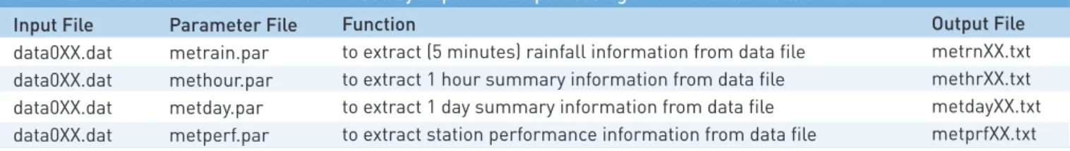
Table 2 presents the various files involved. 0XX stands for the data file’s serial number.
Input File data0XX.dat data0XX.dat data0XX.dat data0XX.dat Parameter File metrain.par methour.par metday.par metperf.par Function
to extract (5 minutes) rainfall information from data file to extract 1 hour summary information from data file to extract 1 day summary information from data file to extract station performance information from data file
Output File
metrnXX.txt methrXX.txt metdayXX.txt metprfXX.txt
Table 2: Various files and their function used by Report in the processing of Met Station measurements.
Each of the four file groups given in table 3 is dealt within more detail in the next four sub paragraphs.
5.3.2.2 Five – Minute Rainfall Data
Only in case of a rainfall event, a cumulative 5 minutes rainfall value is stored into the logger’s RAM at the end of the interval. In contrast, for those 5-minute intervals in which the raingauge sensor has not registered precipitation (i.e. the rainfall values are equal to zero), the zero rainfall values are not stored to avoid loading the datalogger memory with meaningless information. Consequently, the 5-minute rainfall data consists of a 5 minutes time series in which a cumulative non-zero 5-minute rainfall was registered by rain gauge sensor. Consequently, the gaps in the recorded time series indicate dry periods without rain events at the measurement site.
Procedures for the extraction of 5-minute rainfall time series data from a raw input file and storing the result in an output file for final processing is described in the following text:
PC208W Datalogger Support Software
Step C2: Choose Open from the File menu to activate a pre-defined parameter file, as indicated in the following window.
PC208W Datalogger Support Software
Step C3: Navigate to the location on hard drive, which contains the parameter files. This is “C:\CAMPBELL\FILES\ PARAMETR” if the Recommended Directory Structure is used. Highlight the file “metrain.par”, as shown on the window below. Click OK.
The title bar on the Split window now indicates the name of the open parameter file.
Step C4: Activate the Input File(s) sub-window and select the Input Data File. To this end click “Browse” in the Input Data File box and navigate to the location (folder/directory) on hard disk which contains the raw data files. This is pictured in the following screen. Highlight the appropriate file and click OK.
PC208W Datalogger Support Software
Step C5: Switch to the Output File sub-window by clicking its tab at the top-mid of the current Split screen. The below window pops up.
PC208W Datalogger Support Software
Step C6: In the File Name text box of the Selected Output File sub-screen, type in the name of the appropriate output file. Apply the following naming format: “metrnXX.txt”
Make sure that the XX - serial number of the output file – is the same as of the respective raw data file. For instance, give the name “metrn31.txt” to the output file if it is being extracted from “data031.dat” raw data file. Click OK. This process is presented in the windows given below:
Step 7: Finalize the routine by selecting Go from the Run menu. The results, as presented on computer screen, are similar to the window given below:
PC208W Datalogger Support Software
For each five-minute interval in which rainfall has been registered at the station, the following information is extracted from raw input data file: station datalogger-ID, year, date and time and cumulative five-minute rainfall values. The first four values (i.e. ID, year, date and time) guarantee that each array is uniquely identified.
The associated output file is in comma separated ASCII format. This is shown below for the output file “metrn31. txt” referred to in the above screen; the file can be opened and viewed by Windows Explorer or any other software capable of reading ASCII text format. In the following case the respective Output File is opened using the View utility of the PC208W 3.3 software.
PC208W Datalogger Support Software
This concludes the user activities in Report with respect to the extraction of 5-minute rainfall time series data from the respective raw data input file downloaded from storage module.
For ease of reference, the above-presented steps are listed in Annex 3.
5.3.2.3 Hourly Meteorological Time Series
As in the previous, the procedure for extraction of hourly meteorological time series data is similar to the one described in paragraph 5.3.3. The reader is referred to the above text and Annex 3 for detailed instructions on step 1 to 5 keeping in mind that in this case the parameter file “methour.par” should be used.
Steps 6 and 7 are discussed in more detail in the remaining part of this paragraph, even though these steps are also essentially analog to the ones discussed in paragraphs 5.3.3.
Step C1-5: Perform the same actions as presented in the previous paragraph. But now use parameter file “methour.par”.
Step C6: In the File name text box of the Select Output File sub-screen, type in the name of the output file. Apply the following naming format: methrXX.txt
Make sure that the “XX” – serial number of the output file – is the same as of the respective raw input data file. For instance “methr31.txt” if originating from “data031.dat”. Click OK. This process is presented in the below window.
PC208W Datalogger Support Software
Step C7: Complete the routine by selecting Go from the Run menu. The results, as displayed on screen during the programme run-time, are similar to window given below:
PC208W Datalogger Support Software
For each full hour the Met station has been operational, the following hourly meteorological data are extracted from raw input data file: station datalogger-ID, year, date and time, average hourly air temperature, vapor pressure, vapor pressure deficit and wind speed; and total hourly solar radiation. The first four values (i.e. ID, year, date and time) guarantee unique identification of each array.
The associated output file is in comma separated ASCII format. This is shown below for the output file “metrn31. txt” referred to in the above screen; the file can be opened and viewed by Windows Explorer or any other software capable of reading ASCII text format. In the following case the respective Output File is opened using the View utility of the PC208W 3.3 software.
This concludes the user activities in Report with respect to the hourly meteorological data series.
5.3.2.4 Daily Meteorological Time Series
Compilation of daily meteorological information is a similar process as the one described in paragraph 5.3.3 and 5.3.4. The reader is referred to this text, and Annex 3, for detailed instructions on steps 1 to 5. In this particular case the parameter file “metday.par” should be used.
Steps 6 and 7 are discussed in more detail in the remaining part of this paragraph, although all these steps are essentially analog to the ones discussed in paragraph 5.3.3.
Step C1-5: Perform the same actions as presented in the previous paragraph. Use parameter file “metday.par”. Step C6: In the File name text box of the Selected Output File sub-screen, type in the name of the output file. Apply the following naming format: metdayXX.txt
Make sure that the “XX” – serial number of the output file – is the same as of the respective raw data file. For instance, give the name “metday31.txt” to the output file if it is being extracted from “data031.dat”. Click OK. This process is presented in the below given window:
PC208W Datalogger Support Software
Step C7: Complete the routine by selecting Go from the Run menu. The results, as displayed on the computer screen during the programme run-time, are similar to the window given below:
PC208W Datalogger Support Software
For each day the Met station has been operational, the following daily meteorological data are extracted from the respective raw input data file: station datalogger-ID, year and date, average, maximum and minimum daily air temperature, average vapor pressure and vapor pressure deficit; total daily rainfall and solar radiation; average daily wind speed and direction and standard deviation of the wind direction. The first three indices (i.e. ID, year and date) uniquely identify each output array.
The associated output file is in comma separated ASCII format. This is shown below for the output file “metday31. txt” referred to in the previous screen; the file can be opened and viewed by Windows Explorer or any other software capable of reading ASCII text format. In the following case the respective Output File is opened using the View utility of the PC208W 3.3 software.
The first three parameters uniquely identify each output array.
This concludes the user activities in Report with respect to the daily meteorological information.
5.3.2.5 Meteorological Station Performance Information
As already indicated earlier, the METSTAT datalogger programme includes routines for permanent monitoring of the two essential station performance indicators, namely (a) battery voltage and (b) the signature of the active METSTAT datalogger programme.
Detailed instructions to retrieve and evaluate these two indicators are straight forward and by following essentially the same procedures as described above in the paragraphs 5.3.3, 5.3.4 and 5.3.5 – taking care to use the parameter file “metperf.par” instead. For users easy reference these instructions are summarized in Annex 5 of the Manual.
It is strongly recommended to assess performance of the meteorological station after each data retrieval exercise. This will facilitate timely action in case of malfunctioning of the power supply unit at the station (solar panel and/ or battery) or corruption of the METSTAT datalogger programme, thus avoiding unnecessary loss of valuable meteorological data measured at the station.
PC208W Datalogger Support Software
There is no need to archive the output file containing the station performance information. After assessment of the station performance indicators (which will lead to a decision to either take or not take an action) this information can be printed out for records and the respective file deleted thereafter.
5.3.2.6 Renaming Meteorological Output Files
Once the 5-minute rainfall, hourly and daily meteorological data time series data have been extracted and stored in the output files, a consideration should be given to suitably rename them. This may be important in particular when a large number of raw data files (containing measurements from more than one station, as may be the case in Uganda) is downloaded from storage module to PC and processed at the same time; this operation will unavoidably result in a large number of output files of the type “metrnXX.txt”, “methrXX.txt” and “metdayXX.txt” without a possibility to really know to which particular meteorological station these output files refer to, as it is not visible from their names.
To suitably rename the meteorological output files so as to enable the user to figure out both the type of data and the station the data have come from, by merely reading the output file name, the following simple procedure can be used:
immediately after processing the particular raw input file and thus creating an output file of the type “metrnXX. •
txt”, “methrXX.txt” and “metdayXX.txt”, activate Windows Explorer and then open and view the respective output file (for example, open the file “metday31.txt”).
take note of the Station Datalogger ID while viewing the file, and from this ID identify the station datalogger •
the viewed data are coming from (as an example, let’s assume it was established that the extracted data in the output file “metday31.txt” are referring to daily meteorological data observed at the Meteorological Station Kadenge established at the Kenyan part of the Nile Basin).
Close the respective file (“metday31.txt” in our case). •
Highlight the same file again in the Windows Explorer, click the right mouse button and select “Rename” •
option in the menu that will show up on the screen.
Move cursor to the beginning of the file name and type in a three letter prefix which will uniquely define the •
station, without changing/deleting any part of the old output file name (in our example, add say KAD prefix at the beginning of the file “metday31.txt” so that the renamed file reads: “KAD_metday31.txt”.
Click the left mouse button anywhere in the Windows Explorer area to complete the operation and repeat the •
whole above sequence for all other output files.
From a renamed output file the user can now easily identify all the necessary information as follows: (a) what is the station the data have come from (from three-letter prefix, “KAD” in our example signifying the Kadenge Met station); (b) what type of station is in question (from the next group of three characters, “met” in our example signifying the meteorological station); (c) what type of data are stored in the file (from the next group of three or two characters, “day” in our example so the file contains daily meteorological time series data); and (d) what is the name of the raw data file the output data have been extracted from (from the last two characters containing a serial number, in our example “31” denoting that the output file has been extracted from the raw data input file “data031.dat”).
Data Processing in MS Access and Final Storage into the NBD
6.1 General
Final destination of the meteorological data obtained from the Automatic Weather Stations in The Nile Basin Monitoring Network is the NBD: The Nile Basin Database developed in MS Access. But prior to reaching the final step of adding newly observed data to this database, one more intermediate operation has to be performed: importing the ASCII files generated by Report (as described in chapter 5 of this Manual) into MS Access and restructuring them into a final NBD format.
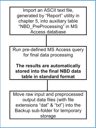
Figure 5 shows the remaining part of the data trajectory, i.e. the preprocessing actions in MS Access.
Final Processing in MS Access and Final
Storage into the NBD
Import an ASCII text file, generated by “Report” utility in
chapter 5, into auxiliary table “NBD_PreProcessing” in MS
Access database
Run pre-defined MS Access query for final data processing
The results are automatically stored into the final NBD data
table in standard format
Move raw input and preprocessed output data files (with file extensions “dat” & “txt”) into the Backup sub-folder for temporary
storage
Figure 5: Final data processing steps in MS Access and subsequent removal and storage of raw files as backups. The following paragraphs will present the detailed instructions for performing the tasks indicated in the above figure.
6.2 MS Access Database “NBD_NEW DATA”
The remaining data processing activities are carried out in an MS Access database file called “NBD_PreProcessing. mdb”. The users will find this file in one of the following folders (given with full path name), depending on the country and this file structure is required to be kept unchanged at all times:
• Users in Kenya: C:\MyDbase\NBD NEW DATA\Kenya Preprocessing • Users in Rwanda: C:\MyDbase\NBD NEW DATA\Rwanda Preprocessing
Data Processing in MS Access and Final Storage into the NBD
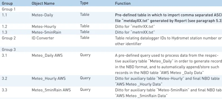
This database file (NBD_Pre Processing.mdb) contains several pre-defined objects including 4 tables and 3 process-append queries. The database tables and queries names are listed in table 4 together with a brief description of their function.
As indicated by their numbering, the various database objects listed in table 4 are divided into three different groups.
Group 1 consists of 3 auxiliary tables in which to import the respective comma separated ASCII files generated •
in Report (see chapter 5).
Group 2 consists of a single ID-converter table used to convert into a final station identification code in •
accordance with either the Hydromet coding system or the one which is in force in each country of the Nile Basin.
Group 3 consists of 3 process-append database queries specifically designed to generate records in the final •
NBD database format from data in the respective auxiliary table in Group 1 and to automatically append these records into the appropriate file and table of the NBD database.
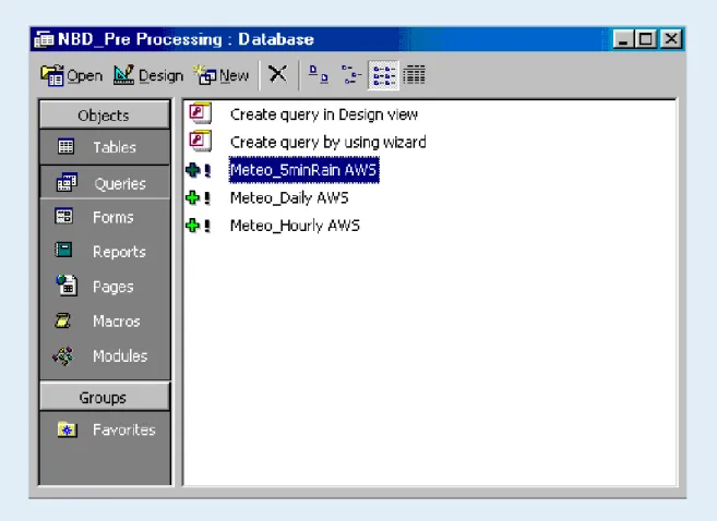
Group Group 1 1.1 1.2 1.3 Group 2 Group 3 3.1 3.2 3.3 Object Name Meteo-Daily Meteo-Hourly Meteo-5minRain ID Converter Meteo_Daily AWS Meteo_Hourly AWS Meteo_5minRain AWS Type Table Table Table Table Query Query Query Function
Pre-defined table in which to import comma separated ASCII file “metdayXX.txt” generated by Report (see paragraph 5.3)
Ditto for “methrXX.txt” Ditto for “metrnXX.txt”
Table relating datalogger IDs to Hydromet station number or other identifier
A pre-defined query used to process data from the respec-tive auxiliary table “Meteo_Daily” in order to generate records in the NBD format, and to automatically append/store such records in the NBD table “AWS Meteo _Daily Data”
Ditto for auxiliary table “Meteo-Hourly” and final NBD table “AWS Meteo _Hourly Data”
Ditto for auxiliary table “Meteo-5minRain” and final NBD table “AWS Meteo _5minRain Data”
Table 3: Database objects and their function in MS Access database file “NBD_Pre Processing.mdb”.
The final NBD tables in which the processed data will ultimately be stored/appended are located in the following database files (including the whole folder/directory path):
NBD tables (a) “AWS Meteo _Daily Data” (b) “AWS Meteo _Hourly Data” and (c) “AWS Meteo _5minRain Data” are located in:
C:\MyDbase\NBD\Daily Hydro-Meteorological Data\Daily Clim Kenya.mdb – for data observed at the •
meteorological stations in Kenya (for the time being there is only one such station established by the Project) C:\MyDbase\NBD\Daily Hydro-Meteorological Data\Daily Clim Rwanda.mdb – for data observed at the •
meteorological stations in Rwanda (there is only one such station).
C:\MyDbase\NBD\Daily Hydro-Meteorological Data\Daily Clim Uganda.mdb – for data observed at the •
meteorological stations in Uganda (there are three such stations established by the previous project and 2 more by the present project in Uganda).
The above paths (folder/directory structure) are included into the respective pre-designed MS Access queries indicated in table 4 and should not be changed by the user as any change of the folder/directory structure will result in loss of the processed data.
Data Processing in MS Access and Final Storage into the NBD
the actions for importing ASCII text file “metdayXX.txt” into MS Access are equivalent to those for “methrXX.txt” and “metrnXX.txt”, only table and file names differ. The same applies for running the various queries and adding the fully processed data to the NBD.
It is because of this fact, and the wish to avoid redundancy, that this manual presents the detailed user instructions for only one member of each data type. The instructions for the remaining members are analog.
Last but not least, if the user decides to suitably rename the output ASCII text files – as described in chapter 5 then the original names of all the respective ASCII output text files given in table 4 above will be different; in this case, each file name will have a three-letter prefix and underscore added to indicate the station name. To illustrate this by using the same examples as in chapter 5, the name of the file “metday31.txt” would change into “KAD_metday31. txt” and so on.
6.3 Importing Output ASCII Text Files Generated by Report into MS Access
This paragraph describes procedures for importing output ASCII text file “methrXX.txt” into MS Access file “NBD_Pre Processing.mdb”. The same or similar commands are applied for importing “metdayXX.txt” and “metrnXX.txt”.
Step D1: Open the MS Access file “NBD_Pre Processing.mdb”; consult paragraph 6.2 above to locate the appropriate folder/directory path of the file, which is country-dependent. In table view, the following database window appear
The above view shows the 4 pre-defined tables as specified in table 4.
Step D2: Highlight the auxiliary table “Meteo_Hourly” and click “Open”. This results is illustrated in the following screen:
Data Processing in MS Access and Final Storage into the NBD
In the above screen, the Meteo_Hourly table still contains data from a previous transfer exercise. Although primary key setting in the final NBD tables do not allow for data duplication, it is good policy to delete all records from the auxiliary tables, in this case Meteo_Hourly, prior to a processing new data set. To this end, continue with step 3.
Step D3: Select all records by simultaneously keying CTRL and A, or clicking Select All Records in the Edit menu. The complete record set is now highlighted.
Step D4: Delete all records by choosing Delete Records from the Edit menu, or by pressing the ‘Delete’ key as shown on the following screen:
Data Processing in MS Access and Final Storage into the NBD
Step D5: Close Meteo_Hourly table.
The auxiliary Meteo_Hourly table is now empty. No data duplication will occur during data import process unless the user imports a certain data set twice. Although this would eventually be refused by MS Access due to ‘key violation’, it is recommended not to enter this situation. Continue with step D6.
Step D6: In the database window, select Get External Data from the File menu. Choose the sub command Import, as presented below.
Step D7: In the subsequent window, navigate to the folder containing the Report output files and select the con-cerned “methrXX.txt” file. Use the appropriate Windows Explorer operations. If the recommended directory structure is used, “methrXX.txt” is stored in folder C:\CAMPBELL\FILES\OUTPUT. Make sure the ‘Files of type:’ box below-left is set to Text Files. The resulting screen is depicted below:
Data Processing in MS Access and Final Storage into the NBD
Step D8: Click Import.
Data Processing in MS Access and Final Storage into the NBD
The Report output files are comma-separated and thus fall into the category ‘delimited’. This has been done on purpose since importing this format into MS Access has proved to be straight forward and flawless. Continue with step 9.
Step D9: Select ‘Delimited” and click ‘Next’. The screen illustrated below appears; it shows how the imported text will be divided into various columns according to the applied delimiter.
Step D10: Select ‘comma’ and click ‘Next’.
The subsequent window (shown below) is used to define the output location for the imported data. In this particular case, the new information is to be imported into an existing pre-defined auxiliary table Meteo_Hourly.
Data Processing in MS Access and Final Storage into the NBD
Step D11: Check “In an Existing Table:” and navigate in the related list box to the Meteo_Hourly table. Click ‘Next’.
This constitutes the final step in importing the ‘methrXX.txt’ ASCII file into the appropriate pre-defined MS Access table. If no importing errors are encountered, the Text Import Wizard finishes the process by giving the following message.
Step D12: Click OK.
The text file is now imported into the desired auxiliary MS Access table Meteo_Hourly. View the results by opening the Meteo_Hourly table in the database window. Check on the integrity of data, in particular, the datalogger ID values and make corrections if necessary. The result is presented on the screen given below:
Data Processing in MS Access and Final Storage into the NBD
This step concludes description of procedures for transfer of the contents of the Report Output file “methrXX.txt” into the appropriate location in MS Access in preparation for final processing of data.
As already stated at the beginning of this paragraph, the import procedures for “metdayXX.txt” and “metrnXX.txt” are analog to the procedures presented above for the file “methrXX.txt”. To import these ASCII files into “NBD_Pre Processing.mdb”, the user is requested to change file and table names where and when necessary.
For easy reference, all steps discussed in this paragraph are again presented, in proper sequence, in Annex 4. This time however without accompanying comments and illustrations.
6.4 Processing of Imported Data in MS Access and Final Transfer into the NBD
After being imported into an auxiliary table in MS Access, the new data sets are subject to the following processing and final storage of processed data records into NBD:
two separate text fields containing day, month and year respectively, have to be converted into a single date •
field;
short datalogger ID (due to the logger’s memory configuration limited to a number below 255) has to be •
converted into an official numerical station identifier, for example in case of Hydromet-IDs consisting of 8 digits;
automatic quality control: checking if the data values are within an expected range of variation; •
adding of ‘source’ value: indicating the origin of the data set; •
re-arranging column structure in accordance with the NBD database format. •
final automatic storage of the processed new data records into the appropriate NBD file and table. •
For each data type, all these actions are automatically performed in one go with a pre-defined query. When the Queries tab is activated in the database view, 3 pre-defined queries appear, as shown in the window below:
Data Processing in MS Acce