Approved Code of Practice
for Load-lifting Rigging
DECEMBER 2012
ACKNOWLEDGEMENTS
The Ministry of Business, Innovation and Employment thanks the Lifting
Equipment Engineers New Zealand Incorporated for their support and assistance with the Code’s revision. The Ministry also appreciates the input from the people and organisations that provided submissions on the proposed changes.
Cover page photograph: A crane lifting a concrete wall into place at a construction site. Photo by Yellow Garnet Photography/iStockphoto.
Disclaimer: The Ministry of Business, Innovation and Employment has made every effort to ensure that the information contained in this report is reliable, but makes no guarantee of its accuracy or completeness and does not accept any liability for any errors. The information and opinions contained in this report are not intended to be used as a basis for commercial decisions and the Ministry accepts no liability for any decisions made in reliance on them. The Ministry may change, add to, delete from, or otherwise amend the contents of this report at any time without notice.
The material contained in this report is subject to Crown copyright protection unless otherwise indicated. The Crown copyright protected material may be reproduced free of charge in any format or media without requiring specific permission. This is subject to the material being reproduced accurately and not being used in a derogatory manner or in a misleading context. Where the material is being published or issued to others, the source and copyright status should be acknowledged. The permission to reproduce Crown copyright protected material does not extend to any material in this report that is identified as being the copyright of a third party. Authorisation to reproduce such material should be obtained from the copyright holders.
First edition published 1974 Revised 1979 Revised 1983 Reprinted 1989 Reprinted 1990 Revised 2001 ISBN 0-477-03595-7 ISBN: 978-0-478-40122-6 (print) 978-0-478-40123-3 (web) November 2012 © Crown copyright 2012
Ministry of Business, Innovation and Employment PO Box 3705
Wellington New Zealand
NOTICE OF APPROVAL
The construction industry plays an important role in New Zealand, working hard to educate its members to a high standard of health and safety. However, it is an industry with significant risks that must be well managed. Load-lifting rigging is a critical aspect of transporting materials over distance and height, and if not done so safely, serious accidents and damage to property can occur.
This Approved Code of Practice has been developed by the Ministry of Business, Innovation and Employment in partnership with industry representatives and other agencies. It is focused on improving safety practices and reducing workplace accidents in the industry.
In May 2012, the Government announced a target of reducing workplace deaths and serious injuries by at least 25 percent by 2020. This code, as a joint
initiative of the Ministry and the industry, will play a role in achieving that goal. I approve this code of practice under section 20 of the Health and Safety in Employment Act 1992. It is a statement of preferred work practices. A Court may consider it when considering compliance with relevant sections of the Act. If an employer can show compliance with all the matters it covers, a Court may consider the employer has complied with the Act.
Hon Christopher Finlayson Acting Minister of Labour
The approval date of this Approved Code of Practice is 21 November 2012. The commencement date of this Approved Code of Practice is 21 May 2013 to allow for a transition period from the approval date.
FOREWORD
As Deputy Chief Executive of Safety and Regulatory Practice at the Ministry of Business, Innovation and Employment, it gives me great pleasure to introduce this Approved Code of Practice for Load-Lifting Rigging (5th edition).
The Ministry is resolute in its commitment work in partnership with industries to reduce the number of workplace fatalities, injuries and occupational disease. In 2011, with two million people working in about 470,000 workplaces, 85 people were killed– that’s 85 colleagues, friends, and family members. Another 445 people were seriously injured, some requiring months of medical treatment and rehabilitation. 33,800 ACC claims were filed for work-related injuries1.
This toll is too high. We must all work together to ensure that all working New Zealanders return home at the end of their working day to their families, their friends, and their communities. We encourage you to work with us to help achieve our goal of reducing worker injuries by at least 25 percent by 2020. The Lifting Equipment Engineers New Zealand (Inc) has worked hard with the Ministry to revise and update the Code’s previous edition. Along with the valued input from a range of stakeholders with interest in load-lifting rigging in
construction, what has been produced is an Approved Code of Practice of high quality that will lead to higher sustainable levels of health and safety in the industry.
Lesley Haines
Deputy Chief Executive, Safety and Regulatory Practice, Ministry of Business, Innovation and Employment
November 2012
1 The State of Workplace Health and Safety in New Zealand (June 2011). Department of Labour, Wellington.
TABLE OF CONTENTS
PART 1: INTRODUCTION ... 9
1.1 Scope and application... 9
1.2 Legislation ... 9
1.3 Interpretation ... 9
1.4 Definitions ... 10
PART 2: GENERAL SAFETY AND EQUIPMENT ... 17
2.1 General ... 17
2.2 Safety systems ... 17
2.3 Personal safety ... 17
2.4 Tools and equipment ... 18
2.5 Further information ... 18
PART 3: EQUIPMENT AND APPROPRIATE SAFETY FACTORS ... 19
3.1 Identification ... 19
3.2 Factors of safety ... 19
3.3 Flat web and round slings ... 19
3.4 Manilla rope ... 23
3.5 Chain and chain slings ... 25
3.6 Uniform method: grade 8 ... 26
3.7 Trigonometric method: grade 80 ... 27
3.8 Wire rope... 28
3.9 Components ... 28
PART 4: ROPE SPLICES... 31
4.1 Fibre rope ... 31
4.2 Wire rope... 31
4.3 Wire rope thimbles ... 31
4.4 Wire rope (bulldog) grips ... 32
PART 5: FITTINGS, SHEAVES AND BLOCKS... 36
5.1 Wedge-type rope sockets ... 36
5.2 Rings ... 36
5.3 Shackles ... 37
5.4 Rigging screws and turnbuckles ... 40
5.5 Snatch, sheave and cargo blocks ... 42
5.6 Lifting beams, spreaders and frames ... 43
5.7 Eyebolts for lifting ... 44
5.8 Chainblocks... 45
5.9 Lever block ... 46
5.10 Hooks ... 46
5.11 Other general gear ... 46
5.12 Inspection ... 46
5.13 Register ... 47
PART 6: RIGGING FOR CRANE WORK ... 49
6.1 General safety requirements ... 49
6.3 Load estimation – weight and centre of gravity ... 50
6.4 Figure 22: Volumes of common shapes... 52
6.5 Load security – balance and stability ... 53
6.6 Structures ... 54
6.7 Packing ... 55
6.8 Slings ... 56
6.9 Good slinging practice ... 67
6.10 Radio communication ... 73
6.11 Winches, sheaves and purchases for flexible steel wire rope ... 74
6.12 Rigging blocks ... 88
6.13 Handling steel plate... 92
APPENDIX 1: THE HEALTH AND SAFETY IN EMPLOYMENT ACT 1992 ... 95
Object of the Act ... 95
Regulations ... 95
Approved Codes of Practice ... 96
Employers’ duties ... 96
Hazard management ... 96
Information for employees and health and safety representatives ... 97
Training and supervision of employees ... 98
Responsibility for employees’ work activities ... 98
Persons in control of a place of work ... 98
Duties of the self-employed ... 98
Duties of principals ... 98
Hirers, sellers and suppliers of plant ... 99
Duties of employees ... 99
Accidents and serious harm recording and notification ...100
APPENDIX 2: THE HEALTH AND SAFETY IN EMPLOYMENT REGULATIONS 1995 ... 102
General duties of employers ...102
Managing specific hazards ...102
APPENDIX 3: THE HEALTH AND SAFETY IN EMPLOYMENT (PRESSURE EQUIPMENT, CRANES AND PASSENGER ROPEWAYS) REGULATIONS 1999 ... 104
Notification duties ...104
APPENDIX 4: CRANE HAND SIGNALS ... 105
APPENDIX 5: REFERENCE DOCUMENTS ... 107
New Zealand and Australian standards ...107
European and other international standards ...107
LIST OF FIGURES
Figure 1: Flat eye sling ... 21
Figure 2: Reversed eye sling ... 21
Figure 3: Plain dee sling ... 21
Figure 4: Dee sling with choker ... 21
Figure 5: Endless sling ... 21
Figure 6: Wide load loop sling ... 21
Figure 7: Reduced eye sling ... 21
Figure 8: Wire rope (bulldog) grip ... 32
Figure 9: Wire rope (bulldog) grip ... 32
Figure 10: Correct method of using bulldog grips to form an eye ... 33
Figure 11: Incorrect method of using bulldog grips ... 33
Figure 12: The measurements featured in these diagrams relate to table 11. ... 34
Figure 13: Wedge-type rope sockets ... 36
Figure 14: Large dee shackle ... 39
Figure 15: Types of rigging screw ... 40
Figure 16: Types of turnbuckle ... 41
Figure 17: Examples of sheaves and cargo blocks ... 42
Figure 18: Calculation for single sheave block (note: SWL should read as WWL) ... 43
Figure 19: Examples of lifting beams... 44
Figure 20: Examples of the centre of gravity of loads ... 51
Figure 21: Example of a load being lifted where the hook is not over the centre of gravity ... 52
Figure 22: Volumes of common shapes ... 52
Figure 23: Minimum recommended corner radius for lifting ... 55
Figure 24: Good standard with adequate radius and no kinking ... 56
Figure 25: Calculations for two-leg slings ... 57
Figure 26: Single-leg slings ... 58
Figure 27: Single-leg slings in basket hitch ... 59
Figure 28: Two single-leg slings used together ... 61
Figure 29: Two-leg slings... 62
Figure 30: Basket hitch and four-leg sling examples ... 63
Figure 31: Shortening clutch ... 68
Figure 32: Hammering down is dangerous ... 69
Figure 33: Compression impacting on a roof truss ... 70
Figure 34: Using tag lines ... 71
Figure 35: Storing chain slings ... 72
Figure 36: sheave groove with rounded-off flared edges ... 74
Figure 37: Reducing the number of parts ... 76
Figure 38: Checking groove for wear ... 77
Figure 39: Jockey sheave ... 78
Figure 40: Examples of lay rope ... 79
Figure 41: Grooved drum calculation example ... 80
Figure 42: Effect of fleet angle on spooling ... 81
Figure 43: Number of running sheaves in each pulley block ... 82
Figure 44: Determining the capacity of a reel for rope storage ... 84
Figure 45: Cable pulling stockings... 85
Figure 46: Cutting a rotation-resistant rope ... 86
Figure 48: Multiplication factors for snatch block loads ... 89
Figure 49: Tension on two falls drifting a load ... 91
Figure 50: Drifting a load ... 92
Figure 51: Examples of plate clamps ... 93
Figure 52: Correct method of turning over a load ... 94
Figure 53: Correct method of turning over a steel bin ... 94
LIST OF TABLES
Table 1: Web slings - WLL capacity (WLL 6:1 capacity rating in tonnes) ... 20Table 2: Six types of slings ... 21
Table 3: Colour coding and lifting capacity of synthetic slings (tonnes) ... 22
Table 4: Maximum WLLs for slings in three-strand hawser laid constructions ... 23
Table 5: Maximum WLLs for slings made of Grade 1 Manila ropes ... 24
Table 6: WLLs: General purpose Grade 80 chain slings - uniform load method ... 26
Table 7: Special-purpose slings - trigonometric method of rating ... 27
Table 8: WLLs for slings constructed from wire ropes with fibre cores 6 x 19 to 6 x 41 ... 29
Table 9: WLLs for slings constructed from wire rope with steel cores 6 x 19 to 6 x 41 ... 29
Table 10: Wire rope grips to DIN 1142 ... 33
Table 11: Wire rope grips - federal specification FCC-450 ... 34
Table 12: Required tightening torque and minimum number of FCC-450 grips to attain 80% of rope minimum breaking load... 35
Table 13: US Federal Specification RR-C-271... 38
Table 14: Large dee shackles to US Federal Specification RR-C-271 ... 39
Table 15: WLLs for rigging screws and turnbuckles to BS4429 ... 42
Table 16: Maximum recommended working loads for collar eyebolts when used in pairs for inclined loading positions ... 45
Table 17: Example register ... 48
Table 18: Example of material weights ... 50
Table 19: Relationship between uniform load method and WLL of single- and multi-leg slings ... 67
Table 20: Temperatures and WLL reduction ... 70
Table 21: Recommended minimum sheave diameters for maximum rope life - multiple of rope diameter ... 75
Table 22: Tabulated safe loads ... 82
Table 23: Tabulated method... 85
PART 1: INTRODUCTION
This Approved Code of Practice (the “Code”) provides recommendations and procedures for safe practice while carrying out lifting and rigging work in industry. In an industry with inherent dangers involving lifting, this Code will assist to increase the focus on safety.
1.1
Scope and application
This Code applies to all places of work at which persons such as an employer, employee, self-employed person, contractor or subcontractor has to use lifting and rigging practices in the course of their duties.
1.1.1 Exclusions
This Code also applies to dry dock and wharf usage, but not ships’ gear.
(a) Maritime Rules Part 49 (Ships’ Lifting Appliances) deals with the testing, examination and inspection of a ship’s lifting appliances and the loose cargo gear stored on board a ship. It also requires the marking of a ship’s lifting appliances and loose cargo gear, and the carriage of a register of
equipment, rigging plan and test certificates for the lifting appliances and gear.
(b) Further information, including exemptions, can be found at
www.maritimenz.govt.nz/Rules
1.2
Legislation
The Health and Safety in Employment Act 1992 (the Act) is the over-arching legislation for health and safety in the workplace and compliance with the Act is mandatory.
The Act is underpinned by a number of Regulations.
The legislation and regulations applicable to this Code are as follows:
Health and Safety in Employment Act 1992
Health and Safety in Employment Regulations 1995
Health and Safety in Employment (Pressure Equipment, Cranes and Passenger Ropeways) Regulations 1999
Extracts are produced in Appendices 1 to 3.
Full copies of the legislation can be obtained from the New Zealand government’s legislation website at www.legislation.govt.nz.
1.3
Interpretation
In this Code, the terms ‘shall’ and ‘should’ are used. ‘Shall’ is used where there is a requirement to meet legal obligations. ‘Should’ is used as a way of indicating the practicable steps the Ministry expects to be taken on a particular matter.
Page | 10 Approved Code of Practice for Load-Lifting Rigging 5th edition
1.4
Definitions
All practicable steps Reference: Section 2A Health and Safety in Employment Act 1992
‘All practicable steps’, in relation to achieving any result in any circumstances, means all steps to achieve the result that it is reasonably practicable to take in the circumstances, having regard to:
the nature and severity of the harm that may be suffered if the result is not achieved; and
the current state of knowledge about the likelihood that harm of that nature and severity will be suffered if the result is not achieved; and
the current state of knowledge about harm of that nature; and
the current state of knowledge about the means available to achieve the result, and about the likely efficacy of each of those means; and
the availability and cost of each of those means. To avoid doubt, a person required by this Act to take all
practicable steps is required to take those steps only in respect of circumstances that the person knows or ought to reasonably know about.
Anchor Means a designated point for the purpose of attaching a working line, safety line or other fall protection system.
Bight Means a curved section or loop in a rope or chain.
Chartered professional engineer (CPEng)
Means a person who is registered and holds a current registration certificate under the Chartered Professional Engineers of New Zealand Act 2002.
A list of chartered professional engineers can be downloaded from the Institute of Professional Engineers New Zealand (IPENZ) website:
www.ipenz.org.nz/ipenz/finding/cpeng/Search/search.cfm
Cheek plate Cheek plates are attached to crane hook blocks. Otherwise known as weight plates or side plates, cheek plates are fixed to the side of the crane’s sheave plates. Cheek plates are
commonly used with large capacity cranes to add extra weight to the hook block.
Competent person Means a person who has acquired, through a combination of qualifications, training or experience, the knowledge and skill to perform the task required.
Confined space Reference:AS 2865:Confined spaces
Means an enclosed or partially enclosed space that is not intended or designed primarily for human occupancy, within which there is a risk of one or more of the following:
An oxygen concentration outside the safe oxygen range.
A concentration of airborne contaminant that may cause impairment, loss of consciousness or asphyxiation.
A concentration of flammable airborne contaminant that may cause injury from fire or explosion.
Engulfment in a stored free-flowing solid or a rising level of liquid that may cause suffocation or drowning.
Construction work Reference: Regulation 2 Health and Safety in Employment Regulations 1995
Means any work in connection with the alteration, cleaning, construction, demolition, dismantling, erection, installation, maintenance, painting, removal, renewal, or repair of:
any building, chimney, edifice, erection, fence, structure, or wall, whether constructed wholly above or below, or partly above and partly below, ground level; and
any aerodrome, cableway, canal, harbour works, motorway, railway, road, or tramway; and
anything having the purpose of drainage, flood control, irrigation or river control; and
any distribution system or network having the purpose of carrying electricity, gas, telecommunications, or water; and
any aqueduct, bridge, culvert, dam, earthwork, pipeline, reclamation, reservoir or viaduct; and
any scaffolding.
Crane Reference: Schedule 1 Health and Safety in Employment
(Pressure Equipment, Cranes and Passenger Ropeways) Regulations 1999
Means a powered device:
that is equipped with mechanical means for raising or lowering loads suspended by means of a hook or other load-handling device; and
that can, by the movement of the whole device or of its boom, jib, trolley or other such part, re-position or move suspended loads both vertically and horizontally; and
includes all parts of the crane down to and including the hook or load-handling device, and all chains, rails, ropes, wires, or other devices used to move the hook or load-handling
device; and
includes the attachments, fittings, foundations, mountings and supports; but
Page | 12 Approved Code of Practice for Load-Lifting Rigging 5th edition
does not include lifting gear that is not an integral part of the crane.
Design verifier Reference: Schedule 1 Health and Safety in Employment (Pressure Equipment, Cranes and Passenger Ropeways) Regulations 1999
Means a person who:
is employed or engaged by an inspection body to carry out the functions referred to in the PECPR Regulations, and
is the holder of a relevant certificate of competence.
Dry dock Means a dock that can be kept dry, or free of water, for shipbuilding or ship maintenance.
Edge protection Reference: Best Practice Guidelines for Working at Height in New Zealand
Means some form of guardrail or barrier designed to prevent a person reaching or falling over an exposed edge.
Employee Reference: Section 2 Health and Safety in Employment Act 1992
Subject to sections 3C to 3F [of the Act], means a person of any age employed by an employer to do any work (other than residential work) for hire or reward under a contract of service; and in relation to any employer, means an employee of the employer.
Employer Reference: Section 2 Health and Safety in Employment Act 1992
Subject to sections 3C to 3F [of the Act] means a person who or that employs any other person to do any work for hire or
reward, and, in relation to any employee, means an employer of the employee.
Fall-arrest system Reference: Best Practice Guidelines for Working at Height in New Zealand
An assembly of interconnected components comprising a harness connected to an anchorage point or anchorage system either directly or by means of a lanyard or pole strap, and whose purpose is to arrest a fall in accordance with the principles and requirements of AS NZS 1891.
Ferrule Means a metal object used for fastening, joining or reinforcement.
Guardrails Reference: Best Practice Guidelines for Working at Height in New Zealand
A rail or barrier secured to standards or upright members, at a height above the work platform of 900 mm (minimum) to 1100 mm (maximum) and erected along the exposed sides and ends of working platforms to prevent persons from falling. It includes a lower rail that is fixed to standards midway between the guardrail and the platform. See the SARNZ Best Practice Guidelines for Scaffolding in New Zealand.
Grommet Means an endless wire rope sling.
Hawser-laid Means a rope or sling made up of three strands, the fibres (or yarns) of which have been twisted together to make the rope or sling.
Hazard Reference: Section 2 Health and Safety in Employment Act 1992
Means an activity, arrangement, circumstance, event, occurrence, phenomenon, process, situation, or substance (whether arising or caused within or outside a place of work) that is an actual or potential cause or source of harm; and Includes:
a situation where a person’s behaviour may be an actual or potential cause or source of harm to the person or another person; and
without limitation, a situation described in subparagraph (i) resulting from physical or mental fatigue, drugs, alcohol, traumatic shock, or another temporary condition that affects a person’s behaviour.
Inertia reel Means a self-locking device used to arrest a fall.
ISO Means the International Standards Organisation.
Lanyard Reference: Best Practice Guidelines for Working at Height in New Zealand
Means a line used to connect a harness to an anchorage point or static line, usually as part of a lanyard assembly, which includes a personal energy absorber.
LEENZ Means the Lifting Equipment Engineers New Zealand
Incorporated, an organisation formed in 1992 to adopt a
common range of Standards for the New Zealand industry and to promote the safe use of lifting equipment.
Page | 14 Approved Code of Practice for Load-Lifting Rigging 5th edition
Lifting appliance Means any appliance (except where defined in the Approved Code of Practice for Cranes) capable of being operated by
mechanical, manual, or other means to raise or lower a load in a vertical or near vertical plane, and includes any lifting tackle.
Lifting beams Means a beam which carries loads from two or more points while being supported by one or more different points.
Lifting frame Means a device made up of more than one lifting beam.
Lifting spreader Means a device which spreads the lifting ropes and is in compression.
Lifting tackle Means any sling, shackle, swivel, ring, hook or other appliances, including lifting beams, frames and spreaders, used in
connection with a lifting appliance or from the hook of a crane.
Notifiable Work: Reference: Regulation 2 Health and Safety in Employment Regulations 1995
Any restricted work, as that term is defined in regulation 2(1) of the Health and Safety in Employment (Asbestos) Regulations 1998:
any logging operation or tree-felling operation, being an operation that is undertaken for commercial purposes:
any construction work of one or more of the following kinds:
o work in which a risk arises that any person may fall 5
metres or more, other than—
work in connection with a residential building up to and including 2 full storeys:
work on overhead telecommunications lines and overhead electric power lines:
work carried out from a ladder only:
maintenance and repair work of a minor or routine nature:
o the erection or dismantling of scaffolding from which
any person may fall 5 metres or more:
o work using a lifting appliance where the appliance has to lift a mass of 500 kilograms or more a vertical distance of 5 metres or more, other than work using an excavator, a forklift, or a self-propelled mobile crane:
o work in any pit, shaft, trench, or other excavation in which any person is required to work in a space more than 1.5 metres deep and having a depth greater than the horizontal width at the top:
o work in any drive, excavation, or heading in which any person is required to work with a ground cover overhead:
o work in any excavation in which any face has a vertical height of more than 5 metres and an average slope steeper than a ratio of 1 horizontal to 2 vertical:
o work in which any explosive is used or in which any explosive is kept on the site for the purpose of being used:
o work in which any person breathes air that is or has been compressed or a respiratory medium other than air.
Operator Means a person who operates any plant or equipment.
Reeving Means to place the rope or webbing sling through a block or eye, or a webbing sling through the eye in the end of the sling.
Rigger/Dogman Reference: Approved Code of Practice for Cranes – Includes the Design, Manufacture, Supply, Safe Operation, Maintenance, and Inspection of Cranes
Means a person qualified to sling loads and direct the lifting and placing operations of a crane.
Rigging Means the use of mechanical load-shifting equipment and
associated gear to move, place or secure a load including plant, equipment, or members of a building or structure and to ensure the stability of those members, and for the setting up and dismantling of cranes and hoists, other than the setting up of a crane or hoist which only requires the positioning of external outriggers or stabilisers.
Safety net Means a horizontal system of nets and their supports, as cited in BS EN 1263-1 Industry safety nets: Safety requirements, test methods.
Serious harm Reference: Section 2 and Schedule 1 Health and Safety in Employment Act 1992
Death.
Any of the following conditions that amounts to or results in permanent loss of bodily function, or temporary severe loss of bodily function: respiratory disease, noise-induced hearing loss, neurological disease, cancer, dermatological disease, communicable disease, musculoskeletal disease, illness caused by exposure to infected material, decompression sickness, poisoning, vision impairment, chemical or hot-metal burn of eye, penetrating wound of eye, bone fracture, laceration, crushing.
Amputation of body part.
Page | 16 Approved Code of Practice for Load-Lifting Rigging 5th edition practitioner or specialist outpatient clinic.
Loss of consciousness from lack of oxygen.
Loss of consciousness, or acute illness requiring treatment by a registered medical practitioner, from absorption, inhalation, or ingestion, of any substance.
Any harm that causes the person harmed to be hospitalised for a period of 48 hours or more commencing within 7 days of the harm's occurrence.
Sheaves Sheaves lead the rope over the head of cranes and hoists and are used in pulley systems to gain a mechanical advantage.
Significant hazard Reference: Section 2 Health and Safety in Employment Act 1992
A hazard that is an actual or potential cause or source of:
serious harm; or
harm (being harm that is more than trivial) the severity of whose effects on any person depend (entirely or among other things) on the extent or frequency of the person’s exposure to the hazard; or
harm that does not usually occur, or usually is not easily detectable, until a significant time after exposure to the hazard.
Standards Standards are quoted throughout this code of practice, but another standard may be acceptable if proved to be equivalent. Standards are used not as a restriction but as a means of compliance with the code of practice.
Tag line Means a rope of suitable strength, construction and length attached with an appropriate recognised bend or hitch to the load, which is used to control the load during lifting or positioning.
Test certificate Means a certificate issued by an authorised person or authority.
WLL Means the working load limit, the maximum working load
designed by the manufacturer. This term is now used instead of SWL (safe working limit).
PART 2: GENERAL SAFETY AND EQUIPMENT
2.1
General
Lifting and rigging often needs to be carried out at a height where the danger from falling is greater than normal. Safety systems will need to be deployed where this is the case.
2.2
Safety systems
A safety system could include either one or a combination of the following devices:
guardrails for edge protection
anchor points and inserts
fall arrest equipment
ropes and slings
lanyards and shock absorbers
inertia reels
safety nets.
For further information on working safely at heights, refer to the Best Practice Guidelines for Working at Height in New Zealand.
2.3
Personal safety
Personal protective equipment includes the following (but is not necessarily restricted to):
a hard hat or safety helmet compliant with AS/NZS 1800* or other appropriate
standard
safety shoes or boots compliant with AS/NZS 2210.1* or other appropriate standard
close-fitting overalls or clothes
close-fitting gloves appropriate for the work being undertaken
ear and eye protection
appropriate fall protection equipment
wet weather clothing
specialist equipment to suit the job at hand
ultraviolet protection:
o sunscreen
o hat
o suitable clothing
high-visibility clothing
respiratory protection suitable for the workplace conditions and hazards.
Page | 18 Approved Code of Practice for Load-Lifting Rigging 5th edition
2.4
Tools and equipment
When climbing and working at heights, the number of tools and items of
equipment carried should be minimal and tools should be secured to a lanyard.
2.5
Further information
Further information on working safely at heights is available from the Ministry of Business, Innovation and Employment (refer to Appendix 5: Reference
PART 3: EQUIPMENT AND APPROPRIATE SAFETY
FACTORS
3.1 Identification
Every lifting appliance and item of loose gear shall be clearly and permanently marked with its WLL by stamping, or where this is impracticable or not
recommended, by other suitable means. Also, a unique identifying numbering system to clearly identify individual items should be used.
3.2 Factors of safety
The factor of safety is the ratio between the minimum breaking load and the working load limit.
The factor of safety for steel wire rope must not be less than 6:1 for web slings and round slings.
The factor of safety for other steel wire rope must not be less than 5:1.
Note: for special-purpose ropes, check the manufacturer’s specifications.
The factor of safety for chain and associated hardware must not be less than 4:1, and the chain for slings shall be to a suitable ISO standard or equivalent grade endorsed for lifting purposes. All chains and fittings should be of the same grade and not be mixed. Grade 80 and Grade 8 are considered to be compatible.
Note: If a higher grade chain or component is used in a sling assembly, the sling must be rated to the lowest WLL of the chain or components being used.
Only grades of chain complying with BS EN 818-7 or equivalent can be used with lifting.
For all other grades above Grade 80, for example Grade 85, Grade 95, refer to the manufacturers’ WLL charts.
The factor of safety for fibre ropes varies depending on the diameter, and must be as per BS EN 1492-4*, or refer to tables 4 and 5.
3.3 Flat web and round slings
Webbing slings are manufactured to comply with AS 1353.1* or equivalent. All slings shall have a minimum 6:1 safety factor.
Table 2 illustrates six basic sling types, with a minimum WLL 6:1 safety factor. The WLL (see table 1) is quoted in kilograms for vertical, choker, or basket applications in single or two-ply construction.
Page | 20 Approved Code of Practice for Load-Lifting Rigging 5th edition
Round slings comprise of a hank of polyester yarn of one or more strands wound together continuously to form an endless sling protected by an outer sleeve. The slings have woven stripes in the outer casing, each of which represents a one tonne working load limit. They may also be colour coded.
The combination of woven stripes with recognised colour codes enables the user to more easily recognise the capacity of the sling even when it is soiled.
Care should be taken when inspecting web slings utilising wear sleeves and particularly in the case where the full length of the sling is not visible. Webbing slings should be inspected for:
cuts or damage to webbing
damage to eyes
damage to metal eyes or other end fittings
chemical damage.
Table 1: Web slings: WLL capacity (WLL 6:1 capacity rating in tonnes)
Nominal sling width No. of Plies
Single-leg slings Endless slings
38mm One Two 0.75 1.50 0.60 1.20 1.05 2.10 1.50 3.00 1.50 3.00 1.20 2.40 2.10 4.20 3.00 6.00 50mm One Two 1.00 2.00 0.80 1.60 1.40 2.80 2.00 4.00 2.00 4.00 1.60 3.20 2.80 5.60 4.00 8.00 75mm One Two 1.50 3.00 1.20 2.40 2.10 4.20 3.00 6.00 3.00 6.00 2.40 4.80 4.20 8.40 6.00 12.00 100mm One Two 2.00 4.00 1.60 3.20 2.80 5.60 4.00 8.00 4.00 8.00 3.20 6.40 5.60 11.20 8.00 16.00 150mm One Two 3.00 6.00 2.40 4.80 4.20 8.40 6.00 12.00 6.00 12.00 4.80 9.60 8.40 16.80 12.00 24.00 200mm One Two 4.00 8.00 3.20 6.40 5.60 11.20 8.00 16.00 8.00 16.00 6.40 12.80 11.20 22.40 16.00 32.00 300mm One Two 6.00 12.00 4.80 9.60 8.40 16.80 12.00 24.00
Table 2: Types of slings
Figure Drawing Description
Figure 1: Flat eye sling
A flat eye sling for vertical or flat use.
Figure 2: Reversed eye sling
A reversed eye sling for choker hitches or where proper alignment of the load is needed – the eyes being in the same plane as the webbing.
Figure 3: Plain dee sling
These slings have the same application as eye slings, but with metal dees. This sling has two plain dees.
Figure 4: Dee sling with choker
This sling has a metal dee in choker form at the end.
Figure 5: Endless sling
The endless sling, or loop sling, is most suitable for bulky and awkward loads where stability and easy contour are important factors.
Figure 6: Wide load loop sling
Wide load loop slings are an extension of the sling. The use of the wide load pad gives the greatest possible bearing surface for delicate loads.
Figure 7: Reduced eye sling
Page | 22 Approved Code of Practice for Load-Lifting Rigging 5th edition Table 3: Colour coding and lifting capacity of synthetic slings (tonnes)
Colour
Tonnes
Vertical Choke Basket 90˚ Basket
Violet 1.0 0.80 1.40 2.0 Green 2.0 1.60 2.80 4.0 Yellow 3.0 2.40 4.20 6.0 Orange* 4.0 3.20 5.60 8.0 Red 5.0 4.00 7.00 10.0 Brown 6.0 4.80 8.40 12.0 Blue 8.0 6.40 11.20 16.0 Grey** 12.0 9.60 16.80 24.0
Note: Other colours may be accepted with supporting certificates.
* From Europe, grey is rated four tonnes and orange is rated 12 tonnes for vertical lifts.
** From Australia, grey is rated four tonnes and orange is rated 10 tonnes for vertical lifts.
3.4
Manilla rope
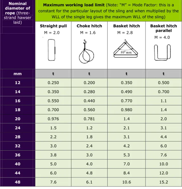
Table 4: Maximum WLLs for slings in three-strand hawser-laid constructions for endless sling configurations Nominal diameter of rope (three- strand hawser laid)
Maximum working load limit (Note: “M” = Mode Factor: this is a constant for the particular layout of the sling and when multiplied by the
WLL of the single leg gives the maximum WLL of the sling)
Straight pull M = 2.0 Choke hitch M = 1.6 Basket hitch M = 2.8 Basket hitch parallel M = 4.0 mm t t t t 12 0.250 0.200 0.350 0.500 14 0.350 0.280 0.490 0.700 16 0.550 0.440 0.770 1.1 18 0.700 0.560 0.980 1.4 20 0.976 0.781 1.4 2.0 24 1.5 1.2 2.1 3.1 28 2.2 1.8 3.1 4.4 32 3.0 2.4 4.2 6.0 36 3.8 3.0 5.3 7.6 40 5.0 4.0 7.0 10.0 44 6.0 4.8 8.4 12.0 48 7.6 6.1 10.6 15.2
Note: Slings having working loads below one tonne are usually marked in kilograms.
One tonne = 1000 kilograms.
Further information is available in the LEENZ Code of Practice*.
Approved Code of Practice for Load-Lifting Rigging 5th edition Page | 24
Table 5: Maximum WLLs for slings made of Grade 1 Manila ropes in three-strand hawser-laid constructions for single strop configurations
Nominal diameter of rope
(three-strand hawser laid)
Maximum working load limit Straight pull
M = 1.0 Choke hitch M = 0.8 Basket hitch 90˚ M = 1.4 Basket hitch parallel
M = 2.0 Two-legged M = 1.4 Four-legged M = 1.4 mm t t t t t t 12 0.125 0.100 0.175 0.250 0.175 0.250 14 0.175 0.140 0.245 0.350 0.245 0.350 16 0.275 0.220 0.385 0.550 0.385 0.550 18 0.350 0.280 0.490 0.700 0.490 0.700 20 0.488 0.390 0.683 0.976 0.683 0.976 24 0.763 0.610 1.1 1.5 1.1 1.5 28 1.1 0.880 1.5 2.2 1.5 2.2 32 1.5 1.2 2.1 3.0 2.1 3.0 36 1.9 1.5 2.7 3.8 2.7 3.8 40 2.5 2.0 3.5 5.0 3.5 5.0 44 3.0 2.4 4.2 6.0 4.2 6.0 48 3.8 3.0 5.3 7.6 5.3 7.6
3.5 Chain and chain slings
Refer to BS EN 818-4 or equivalent for chain and ISO 7593 or equivalent for chain sling, and to tables 6 and 7 of this Code. Further information is available in the LEENZ Code of Practice.
The safety factor for chain slings is 4:1. Chain slings should be inspected for:
corrosion
worn, stretched or deformed links
worn, stretched or deformed hooks and fittings
wear on load pins and to ensure retainers are installed correctly
wear on chain links to be no more than 10% of the original chain thickness. If more than 10%, the chain must be replaced.
Approved Code of Practice for Load-Lifting Rigging 5th edition Page | 26
3.6 Uniform method: grade 8
Table 6: WLLs: General purpose Grade 80 chain slings: uniform load method operating in accordance with EN818-4 (Note: for higher grades, refer to manufacturers' specifications)
Chain size (mm)
Single-leg Two-leg Three-leg Four-leg Choked sling Endless Min dia of pin/lug or lifting member Angle 0˚ t β up to 45˚ α0-90˚ t β 45-60˚ α 90-120˚ t β up to 45˚ α 0-90˚ t β 45-60˚ α 90-120˚ t 0-90˚ t 90-120˚ t mm 6 1.12 1.60 1.12 2.38 1.68 0.89 1.80 7 1.50 2.12 1.50 3.18 2.25 1.20 2.50 30 8 2.00 2.0 2.80 4.24 3.00 1.60 3.15 10 3.15 4.25 3.45 6.68 4.73 2.52 5.00 85 13 5.30 7.50 5.30 11.20 7.95 4.24 8.50 110 16 8.00 11.3 8.00 17.00 12.00 6.40 12.50 135 19 11.20 16.00 11.20 23.80 16.80 8.96 18.00 160 20 12.50 17.70 12.50 26.50 18.80 10.00 20.00 22 15.00 21.20 15.00 31.80 22.50 12.00 23.60 23 16.00 22.60 16.00 33.90 24.00 12.80 26.50 195 26 21.20 30.00 21.20 45.00 31.80 16.96 33.50 220 32 31.50 45.00 31.50 66.80 47.30 25.20 50.00 270
3.7 Trigonometric method: grade 80
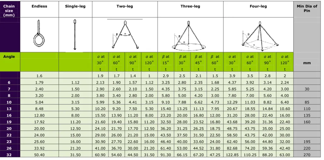
Table 7: Special-purpose slings: trigonometric method of rating(Note: for higher grades, refer to manufacturers' specifications)
Chain size (mm)
Endless Single-leg Two-leg Three-leg Four-leg Min Dia of
Pin Angle α at 30˚ t α at 60˚ t α at 90˚ t α at 120˚ t β at 15˚ t β at 30˚ t β at 45˚ t β at 60˚ t α at 30˚ t α at 60˚ t α at 90˚ t α at 120˚ t mm 1.6 1.9 1.7 1.4 1 2.9 2.5 2.1 1.5 3.9 3.5 2.8 2 6 1.79 1.12 2.13 1.90 1.57 1.12 3.25 2.80 2.35 1.68 4.37 3.92 3.14 2.24 7 2.40 1.50 2.90 2.60 2.10 1.50 4.35 3.75 3.15 2.25 5.85 5.25 4.20 3.00 30 8 3.20 2.00 3.80 3.40 2.80 2.00 5.80 5.00 4.20 3.00 7.80 7.00 5.60 4.00 10 5.04 3.15 5.99 5.36 4.41 3.15 9.10 7.88 6.62 4.73 12.29 11.03 8.82 6.40 85 13 8.48 5.30 10.20 9.20 7.50 5.30 15.40 13.25 11.13 7.95 20.67 18.55 14.84 10.60 110 16 12.80 8.00 15.50 13.90 11.20 8.00 23.20 20.00 16.80 12.00 31.20 28.00 22.40 16.00 135 19 17.92 11.20 21.60 19.40 15.80 11.20 32.50 28.00 23.52 16.80 43.68 39.20 31.36 22.40 160 20 20.00 12.50 24.10 21.70 17.70 12.50 36.20 31.25 26.25 18.75 48.75 43.75 35.00 25.00 22 24.00 15.00 29.00 26.00 21.20 15.00 43.50 37.50 31.50 22.50 58.50 43.75 42.00 30.00 23 25.60 16.00 30.90 27.70 22.60 16.00 46.40 40.00 33.60 24.00 62.40 56.00 44.80 32.00 195 26 33.92 21.20 41.00 36.70 30.00 21.20 61.40 53.00 44.52 31.80 82.68 74.20 59.36 42.40 220 32 50.40 31.50 60.90 54.60 44.50 31.50 91.30 66.15 67.20 47.25 122.85 110.25 88.20 63.00 270
Page | 28 Approved Code of Practice for Load-Lifting Rigging 5th edition
3.8
Wire rope
Refer to BS 302-5* or an equivalent standard, and to tables 8 and 9 for WLLs. For wire ropes not covered by these tables, the WLL is 5:1, based on the manufacturer’s
certificate. Further information may be available in the LEENZ Code of Practice, or as stated by the manufacturer.
Refer to ISO 4309* or equivalent for protocols for discarding wire ropes. Wire rope shall not be used around a diameter less than:
for a soft eye single-leg sling: 2 x rope diameter
for a grommet or basket: 4 x rope diameter.
3.9
Components
The factor of safety of any sling components used in lifting gear and not manufactured to a standard shall be rated in accordance with the equipment it is to be used with, for example:
webbing sling metal components: 4:1
wire rope: 5:1
chain: 4:1.
A sample shall either be tested to destruction or the relevant engineering calculations provided by a competent person, and a proof load test carried out in accordance with the above safety factors.
Table 8: WLLs for slings constructed from wire ropes with fibre cores (1770 tensile strength steel) 6 x 19 to 6 x 41 (excluding 6 x 24)
Rope diameter Single-leg slings Working Load Limit (WLL) Multi-leg slings
Single, terminated by ferrules or splices Single, terminated by grommet Leg angle 0˚ < δ - 90˚ 0˚ < β - 45˚ Leg angle 90˚ < δ - 120˚ 45˚ < β - 20˚
Two-leg Three- or four-leg Two-leg Three- or four-leg
Single Grommet Single Grommet Single Grommet Single Grommet
A B C D E F G H I J K mm t t t t t t t T t t 5 0.276 0.414 0.386 0.579 0.579 0.869 0.276 0.414 0.414 0.621 6 0.398 0.597 0.557 0.836 0.836 1.2 0.398 0.597 0.597 0.895 7 0.542 0.813 0.759 1.1 1.1 1.7 0.542 0.813 0.813 1.2 8 0.762 1.1 1.0 1.5 1.6 2.3 0.762 1.1 1.1 1.6 9 0.962 1.4 1.3 1.9 2.0 2.9 0.962 1.4 1.4 2.1 10 1.2 1.8 1.7 2.5 2.5 3.8 1.2 1.8 1.8 2.7 11 1.4 2.1 1.9 2.9 2.9 4.4 1.4 2.1 2.1 3.1 12 1.7 2.5 2.4 3.5 3.5 5.2 1.7 2.5 2.5 3.7 13 2.0 3.0 2.8 4.2 4.2 6.3 2.0 3.0 3.0 4.5 14 2.3 3.5 3.2 4.8 4.8 7.3 2.3 3.5 3.4 5.2 16 3.0 4.5 4.2 6.3 6.3 9.4 3.0 4.5 4.5 6.7 18 3.8 5.7 5.3 8.0 8.0 11.9 3.8 5.7 5.7 8.5 19 4.3 6.4 6.0 8.9 9.0 13.4 4.3 6.4 6.4 9.6 20 4.7 7.1 6.6 9.9 9.8 14.9 4.7 7.1 7.0 10.6 22 5.7 8.6 8.0 12.0 11.9 18.0 5.7 8.6 8.5 12.9 24 6.8 10.2 9.5 14.3 14.3 21.4 6.8 10.2 10.2 15.3 26 8.0 12.0 11.0 16.8 18.6 25.2 8.0 12.0 12.0 18.0 28 9.3 14.0 13.0 19.5 19.5 29.4 9.3 14.0 13.9 21.0 32 12.1 18.2 16.9 25.4 25.4 38.2 12.1 18.2 18.1 27.3 35 14.5 21.8.1 20.3 30.4 30.4 45.8 14.5 21.8 21.7 32.7 36 15.4 23.1 21.5 32.3 32.3 48.5 15.4 23.1 23.1 34.6 38 17.1 25.7 23.9 35.9 35.9 53.9 17.1 25.7 25.6 38.5 40 19.0 28.5 26.6 39.9 59.8 59.8 19.0 28.5 28.5 42.7
Page | 30 Approved Code of Practice for Load-Lifting Rigging 5th edition
Table 9: WLLs for slings constructed from wire rope with steel cores (1770 tensile strength steel) 6 x 19 to 6 x 41 (excluding 6 x 24)
Rope diameter
Working Load Limit (WLL) Single-leg slings Multi-leg slings Single, terminated by ferrules or splices Leg angle 0˚ < δ - 90˚ 0˚ < β < 45˚ Leg angle 90˚ < δ - 120˚ 45˚ < β - 60˚ Two -leg: Single-part leg Three- or four-leg: single part leg Two-leg: Single part leg Four- leg: single-part leg A L M N P R mm t t t t t 8 0.822* 1.1 1.7 0.822* 1.2 9 1.0 1.4 2.1 1.0 1.5 10 1.3 1.8 2.7 1.3 1.9 11 1.5 2.1 3.1 1.5 2.2 12 1.8 2.5 3.8 1.8 2.7 13 2.1 2.9 4.4 2.1 3.1 14 2.5 3.5 5.2 2.4 3.7 16 3.3 4.6 6.9 3.3 4.9 18 4.1 5.7 8.6 4.1 6.1 19 4.6 6.4 9.6 4.6 6.9 20 5.1 7.1 10.7 5.1 7.6 22 6.2 8.7 13.0 6.2 9.3 24 7.4 10.3 15.5 7.4 11.1 26 8.6 12.0 18.0 8.6 12.9 28 10.0 14.0 21.0 10.0 15.0 32 13.1 18.3 27.5 13.1 19.6 35 15.7 22.0 33.0 15.7 23.5 36 16.6 23.2 34.8 16.6 24.9 38 18.5 25.9 38.8 18.5 27.7 40 20.6 28.8 43.2 20.6 30.9
* WLLs of less than 1 tonne are normally cited in kilograms. Refer to BS 302-5* for
further details.
PART 4: ROPE SPLICES
4.1
Fibre rope
Most common splices, whether in natural fibre or synthetic fibre, are:
eye splice, soft eye
eye splice with thimble
long splice
short splice.
Rope protrusion should be one rope diameter or in accordance with the manufacturer’s specifications or to accepted industry standards.
Eye splices in natural fibre ropes must have a minimum of four full tucks against the lay of the rope or as per industry requirements.
Eye splices in synthetic fibre ropes must have five full tucks against the lay of the rope or as per industry requirements.
4.2
Wire rope
There are various ways of forming eye splices on wire rope for lifting purposes. The following are examples:
manual soft eye, to accepted industry standards
manual hard eye (with thimble), to accepted industry standards
mechanical soft eye (ferrule), in accordance with the manufacturer’s specifications
mechanical hard eye (thimble and ferrule), in accordance with manufacturer’s specifications.
Note 1: The dead end of the wire rope must protrude past the ferrule by one rope diameter, unless it is made to a specific design.
Note 2: There are variable de-rating values depending on the splice configuration used. Wire ropes should be inspected for:
broken wires
kinks and deformation
corrosion
damage to terminations
excessive wear.
For more details, refer to ISO 4309*.
4.3
Wire rope thimbles
The nominal size of a thimble is that of the rope with which it is to be used. Refer to BS EN 13411-1* or equivalent.
Page | 32 Approved Code of Practice for Load-Lifting Rigging 5th edition
4.4
Wire rope (bulldog) grips
Do not use wire rope (bulldog) grips on any load-hoisting rope. Wire rope grips are only suitable for forming an eye on stays or guys. Load-hoisting gives alternating
load/tensions in the wire rope, and this alternating load allows the wire rope to
stretch/narrow and compress/thicken as the load is applied or released. Movement in the wire rope could allow movement in the grip and allow the wire rope to come loose and pull out of the grip.
Wire rope (bulldog) grips must comply with DIN 1142* or equivalent standard as per the
drawings below.
Figure 8: Wire rope (bulldog) grip
Figure 9: Wire rope (bulldog) grip
Figure 10: Correct method of using bulldog grips to form an eye
Figure 11: Incorrect method of using bulldog grips
Table 10: Wire rope grips to DIN 1142
Size nominal diameter
mm
Required number of wire rope grips to attain
85% of rope minimum breaking load Required tightening torque to obtain required efficiency Newton metres 5.0 3.0 2.0 6.5 3.0 3.5 8.0 4.0 6.0 10.0 4.0 9.0 13.0 4.0 33.0 16.0 4.0 49.0 19.0 4.0 68.0 22.0 5.0 107.0 26.0 5.0 147.0 30.0 6.0 212.0 34.0 6.0 296.0 40.0 6.0 363.0
Page | 34 Approved Code of Practice for Load-Lifting Rigging 5th edition Drop forged
Material: high tensile steel
Finish: hot-dipped galvanised
Figure 12: The measurements featured in these diagrams relate to table 11.
Table 11: Wire rope grips - federal specification FF-C-450*
Rope Diameter Bow Diameter Bow Length Bolt Centres Thread Length Base Length Base Thickness Base Height (In) A (mm) B (mm) C (mm) D (mm) F (mm) H (mm) I (mm) 5/16 10 45 22 19 43 33 18 3/8 11 49 26 19 49 42 25 7/16 12 60 30 25 58 46 26 1/2 13 61 30 26 58 48 27 5/8 14 74 33 32 64 52 33 3/4 16 86 38 37 72 57 37 7/8 19 98 45 40 80 62 40 1-0 19 108 48 46 88 67 44 1-1/8 19 117 51 51 91 72 48 1-1/4 22 130 59 54 105 79 56 1-3/8 22 140 60 59 108 79 58 1-1/2 22 147 66 60 112 86 64 1-5/8 26 161 70 67 121 92 67 1-3/4 29 175 78 74 134 97 78 2-0 32 195 86 78 152 113 87
Note: Imperial measurements are used in the first column.
Table 12: Required tightening torque and minimum number of FF-C-450 grips to attain 80% of rope minimum breaking load
Wire Rope Diameter (In) Minimum Number of Grips Torque Value (Ft. Lbs) Wire Rope Diameter (In) Minimum Number of Grips Torque Value (Ft. Lbs) 5/16 2 30 1-1/8 6 225 3/8 2 45 1-1/4 7 360 1/2 3 65 1-3/8 7 360 5/8 3 95 1-1/2 8 360 3/4 4 130 1-5/8 8 430 7/8 4 225 1-3/4 8 590 1-0 5 225 2-0 8 750
Page | 36 Approved Code of Practice for Load-Lifting Rigging 5th edition
PART 5: FITTINGS, SHEAVES AND BLOCKS
5.1
Wedge-type rope sockets
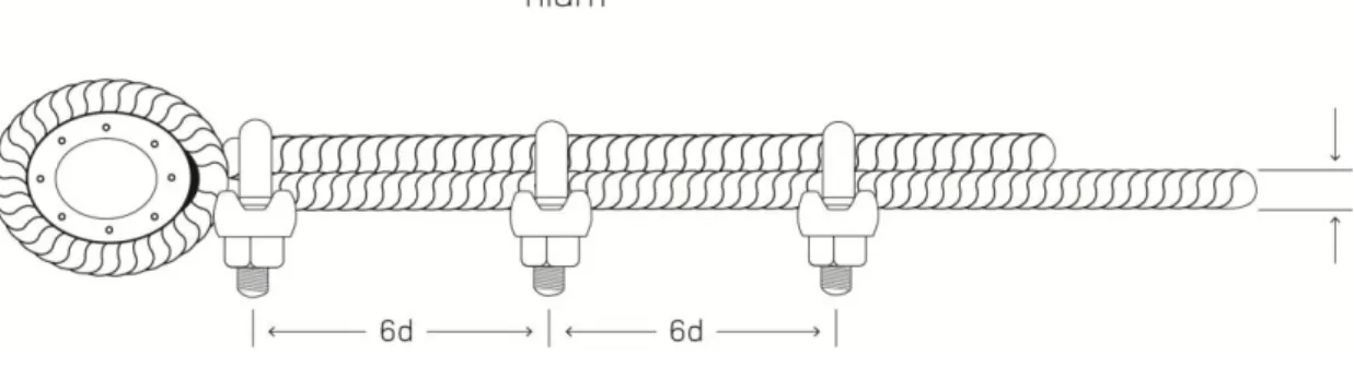
The wedge socket must be properly set up as per the relevant standard BS 7166* or
equivalent. Protruding rope shall be a length of six times the diameter of the rope. Wedge-type rope sockets should be inspected for damage to the rope, wedge and socket.
The wedge should be removed with a pin punch.
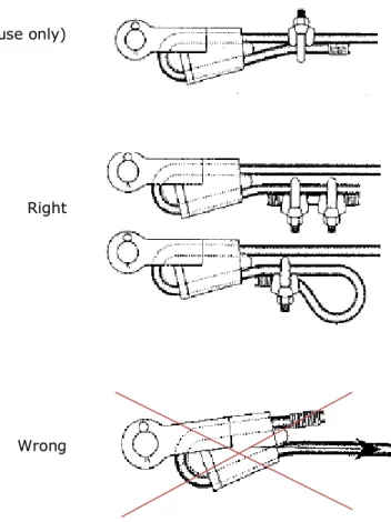
The following three drawings demonstrate correct methods of fitting rope to the wedge and the use of rope grips:
Right (for piling use only)
Right
This method is incorrect:
Wrong
Figure 13: Wedge-type rope sockets
5.2
Rings
Rings for attaching single- and multi-leg slings onto lifting hooks must be of sufficient size and strength to ensure that the safe working capacity of the sling is in no way
impaired. Any attaching of slings to rings must ensure that both can move freely on each
other, and that no undue wear or distortion results in either component. Refer to BS 3458* or equivalent.
5.3
Shackles
Shackles may be made of high-tensile steel or alloy steel. Refer to Federal Specification RR-C-271* or equivalent. Also refer to the Load Chart (table 13).
Shackles used for hoisting purposes must be marked with the WLL. Shackles should be inspected for:
mechanical damage to pin or body
correct tensile pin fitted
correct pin length
wear.
5.3.1 Alloy hi-load standard shackles
Material: Body and pin high tensile steel, quenched and tempered. Safety factor: six times the WLL = minimum breaking strength. Finish: galvanised.
Standard: US Federal Specification RR-C-271 or equivalent.
Page | 38 Approved Code of Practice for Load-Lifting Rigging 5th edition Table 13: US Federal Specification RR-C-271
WLL Diameter
Bow Diameter Pin Inside Width Length Inside of Bow Width Approximate Weight Each
D d a C C 2r Kgs
Metric
tones mm mm mm mm mm mm Screw Pin Safety Pin
0.33 0.50 0.75 5 6 8 6 8 10 10.0 12.0 13.5 27 22 29 32 16 20 21 0.02 0.06 0.11 0.07 0.13 1.00 1.50 2.00 10 11 13 11 13 16 16.0 18.0 22.0 31 37 43 36 43 51 26 29 32 0.15 0.21 0.37 0.17 0.25 0.44 3.25 4.75 6.50 16 19 22 19 22 25 27.0 31.0 36.0 51 59 73 64 76 83 43 51 58 0.65 1.06 1.56 0.79 1.26 1.88 8.50 9.50 12.00 25 28 32 28 32 35 43.0 47.0 51.0 85 90 94 95 108 115 68 75 83 2.32 3.28 4.51 2.78 3.87 5.26 13.50 17.00 25.00 35 38 45 38 42 50 57.0 60.0 74.0 115 127 149 133 146 178 92 99 126 5.93 7.89 13.40 6.94 8.79 14.99 35.00 42.50 55.00 50 57 65 57 65 70 83.0 95.0 105.0 171 190 203 197 222 254 146 160 185 18.85 26.06 37.86 20.65 29.01 41.05 85.00 120.00 75 89 80 95 127.0 146.0 230 267 330 381 190 238 58.68 62.24 110.00
Table 14: Large Dee shackles to US Federal Specification RR-C-271 WLL Tonnes mm d mm D mm a mm C Weight Each Kg 0.25 6 10 13 25 0.11 0.50 10 13 19 38 0.17 0.75 13 16 29 54 0.35 1.50 16 19 32 64 0.66 2.00 19 22 38 73 1.02 3.00 22 25 44 83 1.57 3.75 25 28 51 95 2.30 5.00 28 32 54 105 3.20 6.00 32 35 60 114 4.30 7.00 35 38 67 127 5.40 9.50 38 45 70 137 6.80 11.25 42 48 76 146 8.70 13.00 45 51 83 156 11.00 14.25 48 54 92 178 14.30 16.25 51 57 98 187 20.00 18.00 54 60 105 197 26.38 20.00 57 64 108 210 28.27 25.00 64 73 121 235 35.00 30.00 70 79 133 260 49.03 35.00 76 86 146 279 63.56 40.00 79 89 149 292 71.73 50.00 89 102 171 330 101.24 65.00 102 114 191 375 150.73 80.00 114 127 219 419 214.74
Finish: Self-colour or galvanised.
Page | 40 Approved Code of Practice for Load-Lifting Rigging 5th edition
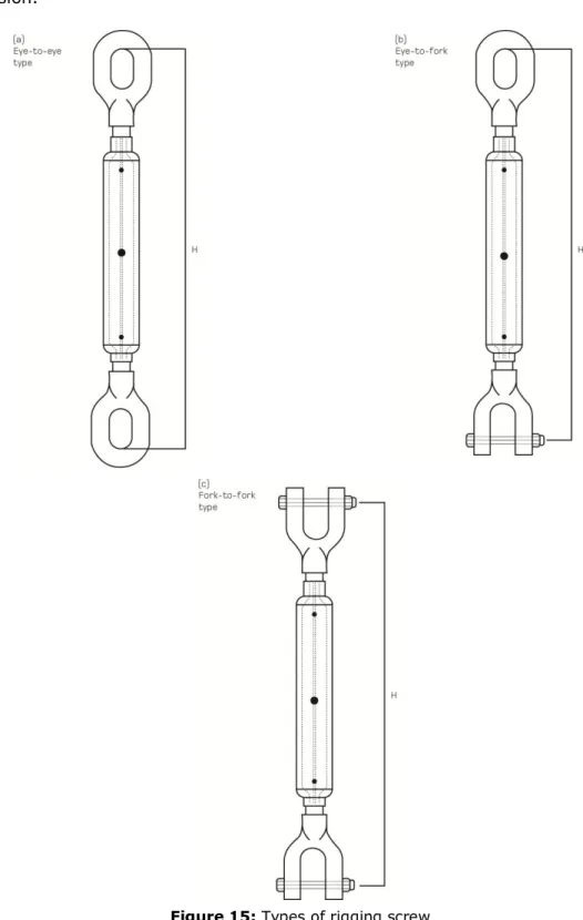
5.4 Rigging screws and turnbuckles
Rigging screws and turnbuckles should conform to BS 4429* or equivalent.
Rigging screws and turnbuckles should be inspected for:
thread damage and thread engaged to a full length of threaded body
deformation
corrosion.
Figure 15: Types of rigging screw
Page | 42 Approved Code of Practice for Load-Lifting Rigging 5th edition Table 15: WLLs for rigging screws and turnbuckles to BS 4429*
Thread Diameter (A) Working load limit (WLL) Thread Diameter (A) Working load limit (WLL) mm tonnes mm tonnes 8 0.2 39 6.0 10 0.3 42 7.5 12 0.5 48 10.0 16 0.75 56 15.0 20 1.25 64 20.0 22 2.0 72 25.0 27 3.0 76 30.0 30 4.0 85 40.0 33 5.0 100 50.0
5.5
Snatch, sheave and cargo blocks
Blocks should comply with the relevant standards:
(a) BS EN 13157 Cranes. Safety. Hand-powered cranes.
(b) AS 1418.2 Cranes (including hoists and winches) – Serial hoists and winches. (c) BS MA 47: Code of practice for ships’ cargo blocks, or equivalent, and tested in
accordance with the relevant standard.
The WLL must be permanently marked on all blocks and the unique identifying number. Sheaves and cargo blocks should be inspected:
(a) for corrosion (b) for deformation
(c) for sheave and pin wear
(d) to ensure the sheave freely turns
(e) to ensure that the snatch block retaining pins correctly retains the gate assembly.
Figure 17: Examples of sheaves and cargo blocks
Figure 18: Calculation for single sheave block (note: SWL should read as WWL)
5.6
Lifting beams, spreaders and frames
Lifting beams, spreaders and frames shall be designed to one of the following:
BS 2573 part 1: Rules for the design of cranes
AS 4991: Lifting devices.
Where the design is to BS 2573 part 1:
welding to AS/NZS 1554.1* and AS/NZS 1554.5* is an acceptable alternative. Structural steels as listed in AS/NZS 1554.1 are acceptable alternatives. Load testing shall be conducted as per AS 4991*.
The design of lifting beams, spreaders and frames shall be certified by a Chartered Professional Engineer or Design Verifier approved by the Ministry of Business, Innovation and Employment as a Crane Design Verifier. The certification documentation shall state:
the WLL
design impact factor
number of lifts it is designed for
duty rating
any other item that may be relevant.
Lifting beams, spreaders and frames shall be marked with WLL (tare weight) in figures large enough to be clearly seen.
Documentation for the test load and date need to be clearly seen.
Documentation for the test load and date need to be signed and witnessed by a competent person and then held by the owners of the lifting beam.
Page | 44 Approved Code of Practice for Load-Lifting Rigging 5th edition Figure 19: Examples of lifting beams
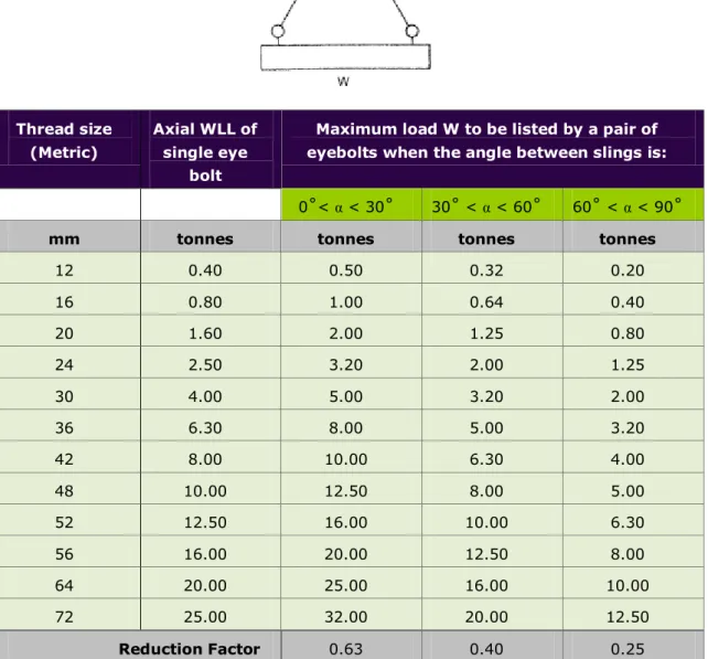
5.7
Eyebolts for lifting
Refer to relevant Standard BS 4278* or equivalent.
Eyebolts with the pull horizontal to the plate should be shoulder-type only and used in pairs. The load taken by a single eyebolt should be no more than 25% of its marked WLL.
Eyebolts must be tightened so that the shoulder is flush with the item being lifted.
* Refer to Appendix 5: Reference Documents Lifting beam
Table 16: Maximum recommended working loads for collar eyebolts (metric threads) when used in pairs for inclined loading positions
Thread size (Metric)
Axial WLL of single eye
bolt
Maximum load W to be listed by a pair of eyebolts when the angle between slings is:
0˚< α < 30˚ 30˚ < α < 60˚ 60˚ < α < 90˚
mm tonnes tonnes tonnes tonnes
12 0.40 0.50 0.32 0.20 16 0.80 1.00 0.64 0.40 20 1.60 2.00 1.25 0.80 24 2.50 3.20 2.00 1.25 30 4.00 5.00 3.20 2.00 36 6.30 8.00 5.00 3.20 42 8.00 10.00 6.30 4.00 48 10.00 12.50 8.00 5.00 52 12.50 16.00 10.00 6.30 56 16.00 20.00 12.50 8.00 64 20.00 25.00 16.00 10.00 72 25.00 32.00 20.00 12.50 Reduction Factor 0.63 0.40 0.25
Some eye bolts, whilst complying with British standards, may be marked with lower working load limits than those shown. In these cases, the reduced working load limit for angular loading when used in pairs may be obtained by using the reduction factor given at the foot of Table 16 for each type of eye bolt.
5.8
Chainblocks
Refer to AS 1418.2* or equivalent. Chainblocks must be supplied with relevant test
certificates and used in accordance with the manufacturers’ recommendations. All components must have a regular inspection.
Page | 46 Approved Code of Practice for Load-Lifting Rigging 5th edition
5.9
Lever block
Refer to AS 1418.2* or equivalent. They shall be supplied with relevant test certificates
and used in accordance with the manufacturers’ recommendations. All components must have a regular inspection.
5.10
Hooks
Refer to BS EN 1677-5* or equivalent.
Safety catches are to be fitted to hooks unless fitting and removal of the load cannot be physically achieved with a catch fitted, for example: using a molten metal pouring ladle in a steel works.
Hook wear in the lifting area is to be no more than 10% of the hook diameter at that position. The hook/opening throat is to open no more than 5% of the opening.
Hook blocks with cheek/side plates attached are to be checked daily and before each lift to ensure their fixing/welding is secure.
5.11 Other general gear
Tirfor-type winches must be used in accordance with the manufacturers’ specifications using the correct rope size and construction.
Lifting components cast in concrete shall have a minimum safety factor of 3:1.
Lifting clutches/eyes for use in lifting items shall have a minimum safety factor of 5:1. Any other lifting equipment must be in accordance with the manufacturer’s
recommendations.
5.12
Inspection
It is recommended that all lifting tackle shall be examined by a competent person on a regular basis. This should not exceed a 12-month period, depending on frequency, type of use, and environmental conditions. It is also recommended that for heavily used tackle, proof loading should be carried out every year.
Visual inspection prior to and after use is a requirement.
Any proof loading shall be carried out by a competent person in accordance with the relevant standard or the manufacturer’s recommendations. Proof loading must be carried out after any repair, replacement or alteration, along with the examination by a competent person.
5.13
Register
A register should be kept for lifting tackle, but this is not required for flat web, round slings, wire rope slings, or shackles. An example of this register is shown in table 17. The register should show the date of the last recorded examination or test, and any alterations.
Approved Code of Practice for Load-Lifting Rigging 5th edition Page | 48 Table 17: Example register - thorough examination of all chains, ropes or lifting tackle
Size Distinguishing number of mark and description sufficient to identify the chain, rope or lifting tackle Number of certificate of test and examination Date when chain, rope or tackle was first
taken into use
Particulars of each thorough examination of all chains, ropes or lifting tackle
Date and by whom carried out Particulars of any defect found which may affect the same working load, and steps taken to
remedy such a defect. (To be initialled and dated)
Date and
PART 6: RIGGING FOR CRANE WORK
Further information is available in the LEENZ Code of Practice*.
6.1
General safety requirements
Load-lifting rigging is a hazardous activity. Only trained and experienced personnel should be permitted to undertake rigging activities.
Employees undertaking training in rigging work may conduct load-lifting rigging activities provided that they are directly supervised by a person trained and experienced in rigging practice until they are deemed to be competent.
The following general safety requirements should be followed:
Keep inexperienced personnel clear of loads swinging overhead, bights of slack rope, lead and snatch blocks, anchorages, or other possible danger points.
Be sure of the weight to be handled, where it is to be placed, and the capabilities of the gear to handle it.
Decide the method of slinging and check that suitable slings are on hand.
Check that the swing area is clear of power lines or other obstructions.
Prepare or select anchorage points if these are required for tie-backs.
Once preparations for a lift are complete, proceed with the lift without stopping.
Lifting equipment should be attached to the load by a competent person, and the immediate areas cleared in preparation for the lift.
Visual and audible alarms are recommended to warn people to clear the area prior to the start of the lift.
Exclusion zones shall cover the area directly underneath the operating and lifting area of the crane or lifting appliance.
Standard signals should be given by one designated person only. “Stop” commands can be given by anyone, and should be obeyed instantly.
Ropes spooling onto winches should be guided by a piece of wood or similar, not by the hands. Hands should be kept clear of moving ropes, especially near blocks, and kept clear of sling eyes as the load is lifted. Keep fingers out from under loads, especially steelwork.
Under no circumstances should anyone pass or stand underneath a suspended load.
Everyone should be outside the lift or drop zone when slewing.
6.2
Evaluating the load
The operator should take all practicable steps to establish the weight of any load. An intelligent “guess” is not good enough. A drawing may be available giving the weight, or it may be calculable within reasonable limits of accuracy. In the case of multi-piece loads (for example, a bundle of steel rods), one item may be weighed to calculate the total weight of the load. If it is likely that the load may have to be lifted again, the weight should be clearly marked on it.
Page | 50 Approved Code of Practice for Load-Lifting Rigging 5th edition
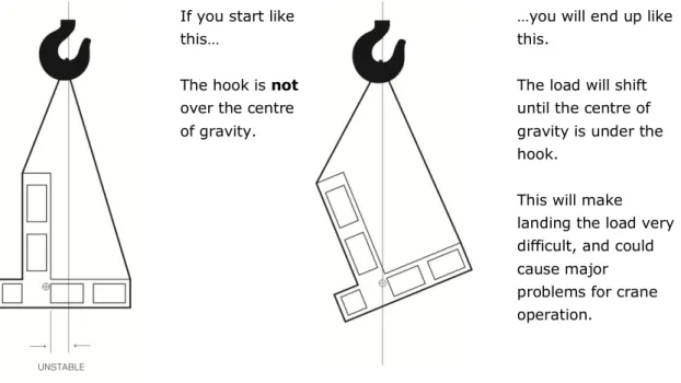
6.3
Load estimation – weight and centre of gravity
The importance of knowing, with reasonable accuracy, the weight of a load to be lifted and the position of its centre of gravity, is stressed throughout this Code. The following gives guidance as to the various ways of obtaining this information.
6.3.1 Weight
Look to see if the weight is marked on the load. If it is, check to ensure that it is the weight of all parts of the load; (a machine tool, for example, may not include the driver motor).
Check the weight stated on any documentation.
Look at the drawing of