Universal IP Multicast Delivery
∗Beichuan Zhang
Computer Science DepartmentUniversity of California Los Angeles, CA 90095
[email protected]
Sugih Jamin
† Department of EECS University of Michigan Ann Arbor, MI 48109[email protected]
Lixia Zhang
Computer Science Department University of California Los Angeles, CA 90095
[email protected]
ABSTRACT
Many applications can benefit from ubiquitous availability of multicast delivery. Unfortunately IP multicast coverage on the Internet is spotty at best, limited to individual cam-puses and a handful of service providers. In response to the slow deployment of IP multicast, a number of end-host mul-ticast mechanisms have been developed. End-host mulmul-ticast lowers the deployment barrier of multicast technology by moving multicast functionality from routers to hosts. Their performance, however, cannot be as good as that of native IP multicast.
We present a framework called Universal Multicast (UM) which integrates end-host multicast with deployed IP mul-ticast islands to achieve ubiquitous mulmul-ticast delivery. We intend UM to be a general framework that can work with various end-host multicast protocol to build dynamic uni-cast tunnels to connect IP-multiuni-cast enabled “islands.” The design of UM takes full advantage of deployed IP multi-cast where available and utilizes end-host multimulti-cast where needed. An important feature of the UM design is to allow multiple connecting points per IP multicast island. In this paper we show that when an IP multicast island is large in size, having multiple connecting points can significantly speed up packet delivery and reduce traffic concentration.
1.
INTRODUCTION
IP multicast [6] can provide efficient data delivery to po-tentially large number of destinations. However, since its deployment imposesdependency on routers, full deployment has been long in coming. Today’s Internet only has spotty IP multicast deployment, within individual campuses and a handful of service providers. Alternate approaches to ∗This research is funded by NSF grant number ANI-9902925.
†Sugih Jamin is supported in part by the NSF CAREER Award ANI-9734145, the Presidential Early Career Award for Scientists and Engineers (PECASE) 1998, and the Alfred P. Sloan Foundation Research Fellowship 2001.
Permission to make digital or hard copies of all or part of this work for personal or classroom use is granted without fee provided that copies are not made or distributed for profit or commercial advantage and that copies bear this notice and the full citation on the first page. To copy otherwise, to republish, to post on servers or to redistribute to lists, requires prior specific permission and/or a fee.
NGC ’02 10/02 Boston, MA, USA
Copyright 2002 ACM ...$5.00.
multicast delivery have been proposed, e.g., Source-Specific Multicast [11], Simple Multicast [14], REUNITE [16] and Hop-By-Hop Multicast [5]. While these approaches gener-ally make improvements or simplifications to some aspects of IP multicast, they do not remove router dependency that forms the major hurdle to widespread IP multicast deploy-ment. An alternative to router-dependent multicast is to let end-hosts form a multicast group to replicate and forward packets on behalf of the group. A number of end-host mul-ticast mechanisms have been developed over the last few years, e.g., [13, 15, 10, 2, 4, 1, 8]. Deployment of end-host multicast can be performed by end users or even auto-matically by application codes. End-host multicast reduces the scaling concern associated with IP multicast since un-der end-host multicast routers do not need to maintain any multicast state. However, doing multicast at end hosts does incur some performance penalty. End hosts do not generally have access to routing information, thus building a multicast overlay network requires hosts to take end-to-end measure-ments to infer network delay or bandwidth metrics. Routing in end-host multicast is thus inherently less efficient.1
In [18], we propose a Universal Multicast (UM) frame-work that integrates end-host multicast and deployed IP multicast. UM uses an end-host multicast protocol to build dynamic unicast tunnels by connecting IP-multicast enabled “islands.” Within each island, native IP multicast is used for internal multicast delivery. One or more Designated Mem-bers (DMs) are elected to be responsible for inter-island tun-nels. Multiple DMs per IP multicast island can speed up packet delivery and reduce traffic concentration, especially when the IP multicast island is large in size. The use of mul-tiple DMs per IP multicast island is, however, not straight forward, as IP multicast was not designed to take into ac-count the use of end-host multicast for inter-island commu-nication, nor was any end-host multicast protocol designed to work with large IP-multicast islands. In this paper we present an intra-island multiple-DM management protocol called Host Group Management Protocol (HGMP). HGMP deals with problems such as how to dynamically elect DMs and how multiple DMs can collaborate to load balance and forward packets.
2.
UNIVERSAL MULTICAST OVERVIEW
The purpose of Universal Multicast is to provide ubiq-uitous best-effort multicast delivery service. Similar to IP 1A more thorough review of related works in end-host mul-ticast is available in [18]. See [17] for discussions on the performance drawbacks of end-host multicast protocols.
IP multicast Universal Multicast Host extension kernel support user-level agent Local membership IGMP HGMP Intra-island DVMRP, PIM, using deployed multicast routing MOSPF, CBT IP multicast Inter-island MASC/BGMP, end-host multicast multicast routing MBGP/MSDP protocols
Table 1: Analogy between IP Multicast and Univer-sal Multicast
multicast, UM is not a single protocol but rather a set of components operating at various levels of the network pro-tocol stack (see Table 1). One key difference between IP multicast and UM is that while IP multicast requires admin-istrative management of its network infrastructure, UM is largely self-organized. UM design is not confined to the use of any particular end-host multicast protocol, rather, it can accommodate most multicast routing protocols. The first design criterion of UM is to preserve end-host multicast’s de-ployability, which means that the service should not require support from routers, servers, tunnel end-points, or operat-ing systems. The second design criterion is to becompatible with IP multicast. UM supports the IP multicast service model and automatically uses IP multicast where available. Applications using Universal Multicast send and receive na-tive IP multicast packets. The third design criterion is to be open to future deployment of network support, such as en-abling IP multicast routers and deploying dedicated servers. The system should automatically take advantage of these network supports where available.
2.1
End-host Multicast Requirements
While the UM framework is not tied to any particular end-host multicast protocol, its design does assume a certain end-host multicast architecture as exemplified by the Host Multicast Tree Protocol (HMTP) [18]. In particular, in de-signing the UM framework, we assume that an IP-multicast “island” is a network of any size that supports IP multi-cast. It can be a wide area network, a campus network, an Ethernet segment, or just a single host. The boundary of an island is the furthest extent an IP multicast packet can travel in the network. Within each island, one or more group members are elected as Designated Members (DMs). Each DM runs a daemon program (UM agent) in user space to provide all UM functionalities, which include running an end-host multicast protocol to build inter-island unicast tun-nels. Application data sent over UM is encapsulated and sent from island to island over these tunnels. A DM extract encapsulated tunneled packets and sends them into its local island by IP multicast. It also encapsulates IP multicast packets generated by local hosts for forwarding to the other islands. Fig. 1 shows the structure of a sample UM group.
We also assume that each UM group is associated with a rendezvous host and group identifier (GID). The address of the rendezvous host and GID together uniquely identify a UM group globally. To join a UM group, a member ob-tains the rendezvous host’s address in an offline manner. From the rendezvous host, the member obtains the group’s identifier. For members not already residing in an existing island, the rendezvous host helps bootstrap the member into the inter-island overlay. The rendezvous host keeps
informa-PXOWLFDVWURXWHU QRUPDOPHPEHU XQLFDVWWXQQHO ,30XOWLFDVW 1HWZRUN HQGKRVW /$1 GHVLJQDWHGPHPEHU QRQPHPEHU URRW UHQGH]YRXV
Figure 1: A Universal Multicast group, with single DM in each island and a shared-tree for inter-island routing
tion such as the end-host multicast protocol in use; it also keeps protocol-specific information such as a partial list of current members or the root of the group shared-tree. The rendezvous host in UM is not involved in packet forwarding, hence its location does not have a significant impact on UM’s performance. The end-host multicast protocols Hypercast [12], Narada [4], and Yoid [8] all satisfy these architectural requirements.
Finally we assume the existence of a well-known multicast session directory within each IP multicast island [9]. To en-sure IP multicast compatibility, a native IP multicast group, DATA GROUP, is used for data dissemination within each island. A local DM maps a GID to a local DATA GROUP and announces it to the local multicast session directory. The operation of this and other functionalities of the DMs is described in the remainder of this paper.
3.
HOST GROUP MANAGEMENT
PROTO-COL (HGMP)
HGMP specifies how a DM is dynamically elected and how multiple DMs of the same island cooperate with each other. We first discuss the simple scenario where one island has only a single DM, then we extend the discussion to the case of multiple DMs per island.
3.1
Single Designated Member
It makes no difference to the end-host multicast protocol used for inter-island multicast delivery whether a member host is an isolated host or is serving as a DM for an IP-multicast island. The question is how group members resid-ing on an island recognize each other and elect a DM among themselves.
3.1.1
End-Hosts Only
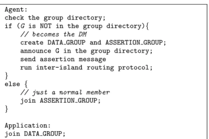
When a host joins a UM group G, it first checks the lo-cal well-known group directory for an announcement for G. If no such announcement is present, it assumes the role of the local DM for G. It then creates two new IP multicast groups locally, DATA GROUP and ASSERTION GROUP, associates them with G, and announces the mappings to the local well-known multicast group directory (see Fig. 2).
The DM of a group G periodically sends ASSERTION messages to G’s ASSERTION GROUP. All members of G
Agent:
check the group directory;
if (G is NOT in the group directory){
// becomes the DM
create DATA GROUP and ASSERTION GROUP; announce G in the group directory; send assertion message
run inter-island routing protocol; }
else {
// just a normal member
join ASSERTION GROUP; }
Application: join DATA GROUP;
Figure 2: Join Group G (Single-DM Model)
must continuously listen to G’s ASSERTION GROUP. When all applications running on the host acting as a DM for group G are no longer interested in G, the DM sends a QUIT message to the ASSERTION GROUP of G.2 When current members of G receive the DM’s QUIT message, or after missing the DM’s ASSERTION messages for a number of periods, they elect a new DM by scheduling their own ASSERTION messages to be sent out after a random de-lay. The first member to send out its ASSERTION message becomes the new DM, others cancel the sending of their AS-SERTION messages. A tie can be resolved by picking the member with the smallest IP address.
To reduce packet loss during change of DM, the old DM continues to forward packets after sending its QUIT message for a short period of time. To ensure smooth transition to a new DM, each ASSERTION message carries information on inter-island routing (e.g., the parent and children nodes on the end-host multicast tree). With this information, a new DM can quickly establish the necessary tunnels to other islands and re-create the inter-island multicast tree if the current DM crashes. ASSERTION messages are sent out at a faster rate than the group advertisement rate to speed up detection of crashed DM. This explains why we use a separate ASSERTION GROUP for each multicast group G instead of simply relying on the cessation of advertisements on the group directory to detect crashed DM.
One enhancement to the basic DM election mechanism is to favor hosts that have more resources. Each host has a pri-ority computed as a function of its resources. This priority is included in the ASSERTION message. A message with higher priority always wins over, or suppresses, a message with lower priority, regardless of the messages’ relative sent order. Thus a host with Ethernet connection can take over the role of DM from a current DM with a dial-up connec-tion. However beware that too many priority levels could lead to many DM changes as members join and leave the multicast group. Hence we stipulate the use of only a small number of priority levels, e.g., based only on DMs’ type of access technology.
2We design for a DM to quit the end-host multicast group when there are no longer any co-hosted applications to re-move a disincentive host owners may have to become a DM. Depending on implementation, a DM could be configured upon startup to continue serving an island even in the ab-sence of co-hosted applications, thereby reducing service dis-ruption due to changing of the DM (see for example the dedicated server scenario in the subsequent subsection).
3.1.2
Dedicated Server
Using normal hosts as DM is necessary to meet UM’s deployability requirement. Nevertheless, when a dedicated server with more computing power and network bandwidth is available, using it as the DM can improve the performance and stability of data delivery. Servers are usually also more stable and properly managed. While a normal host would leave a group when applications running on it are no longer interested in the group, a dedicated server can keep forward-ing a group’s traffic until the last member of the group in the local area network (LAN) leaves the group. This reduces the number of DM changes and enhances the stability of the forwarding service.
To set up a server on a LAN segment, it can be config-ured with an election priority higher than normal hosts’. Servers do not actively participate in DM election, instead, they passively monitor the group directory and all ASSER-TION GROUPs. Upon seeing an ASSERTION message from a host in the same LAN segment as the server, the server sends out its own, higher-priority ASSERTION mes-sage. In this way, a server will always supersede normal hosts in becoming a DM. A server ceases its role as DM for a group on its LAN when it no longer detects IGMP pack-ets for the group on the LAN.3 If no IP multicast router exists in the LAN, the server could act as an IP multicast router and send IGMP queries to solicit IGMP replies from members.
While a server’s assumption of a DM role is based on de-tecting others members on its LAN, its ASSERTION mes-sages are sent to the whole island (which could contain mul-tiple LAN segments). This design decision follows similar motivation for allowing a host to cease being a DM for an is-land upon departure of all co-hosted applications interested in a multicast group: we want to remove a disincentive LAN administrators may have in hosting a UM server.
Since servers rely on IGMP messages to detect group membership, it cannot subsume a DM from another LAN. However, since a server’s ASSERTION message is sent island-wide, only one DM with the highest priority will be elected for the whole island. On islands with multiple LAN seg-ments, when there is no members in the LAN segment in which a server resides, the server will not become a DM (or will cease being a DM), and other members must elect a DM among themselves. To reduce service disruption when a server leaves a group, it can follow the same departure protocol as normal DMs.
Backup servers can be similarly configured with a prior-ity lower than that of the primary server’s, but higher than normal hosts’. During DM election, backup servers auto-matically take over if the primary server does not send out an ASSERTION message. If all servers are down, a normal host will be elected to be the DM by the basic election algo-rithm. Thus the deployment of servers is totally transparent to hosts and applications, except in performance improve-ment.4
3As specified, IGMP messages are not propagated beyond a single LAN [7].
4One could imagine configuring a server to serve the whole island instead of just its own LAN. However, since IGMP messages are not propagated beyond a single LAN seg-ment, this configuration would require further extensions to HGMP such that servers can determine the continuing inter-est of hosts on its island in any particular multicast group.
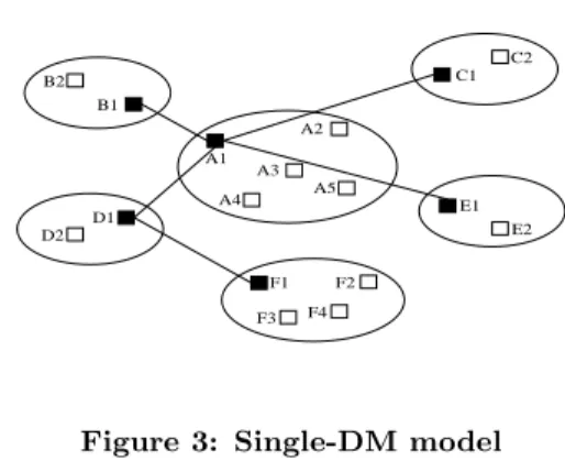
A1 A3 A4 A5 A2 B2 B1 F1 F3 F4 F2 C2 C1 D2 D1 E2 E1
Figure 3: Single-DM model
3.2
Multiple Designated Members
The single-DM model works fine for small IP multicast islands. For a large IP multicast island, this model can result in potential performance problems such as long latency and high traffic concentration. In this section, we discuss how the multi-DM model can alleviate these problems by better utilization of underlying network resources. We also discuss how multiple DMs on an island must coordinate to avoid conflicts with inter-island multicast routing.
3.2.1
Shortcomings of the single-DM model
When there is only one DM in an island, all the group traffic coming into or going out of the island must be pro-cessed by the DM. This leads to two potential problems in large IP multicast islands. For example, in Fig. 3, there are six islands, each with a single DM. Assume the inter-island routing protocol builds a shared-tree among these islands. The ideal way to send a packet from island E to island A is to let E1 send it to A5, and A5 multicast it within island A. However, in Fig. 3, packets from E1 must detour through A1 to enter island A. This results in longer delivery delay for members in island A. If A5 is chosen as the DM, then longer delay are incurred by packets coming from island B. The size of the delay penalty depends on the size of the island and the distribution of member hosts in the island. When there are many group members scattered in a large is-land, with multiple inter-island tunnels to other islands, the DM’s location will have significant impact on performance (e.g., latency) of data delivery. It is difficult for a single DM to deliver good performance to all members in an island.
The other problem is that the single DM becomes a point of traffic concentration because it has to handle all the traf-fic coming in and out of the island. In a large island, other members can likely reduce traffic concentration by using al-ternate paths. For example, in Fig. 3, A5 can take care of the tunnel to E1, so that A1 only needs to handle three tun-nels. Under the single-DM model, A1 and A5 cannot be DM at the same time. Both problems of longer delay and higher traffic concentration still exist if the inter-island topology in Fig. 3 is a per-source tree. Thus these shortcomings are in-herent to the single-DM model regardless of the inter-island routing protocol used.
In any case, for large islands we believe the multiple-DM model described in the next section will be more suitable.
3.2.2
Multi-DM Model
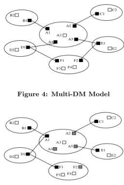
A natural solution to the above problems is to allow each island multiple DMs. In Fig. 4, island A has four DMs and island F has two. A1, A2, A4 and A5 share the work-load of packet forwarding as each maintains a unicast tun-nel. Packets coming into or going out of island A now take shorter paths than always having to detour through A1. The multi-DM model thus solves the problems with the single-DM model. However, it has problems of its own, namely how to elect multiple DMs per island and how to coordinate inter-island multicast forwarding in the presence of multiple DMs.
In the single-DM model, an ASSERTION message can travel the full extent of an IP multicast island. The first group member to send out an ASSERTION message thus effectively suppresses all the other members from becom-ing a DM. To allow multiple DMs, we need to modify this behavior in two aspects: (1) the assertion scope must be allowed to be smaller than the data scope, and (2) overlap of assertion scopes must be tolerated.
When assertion scope is smaller than data scope, mem-bers outside the scope of an ASSERTION message will not hear the message, hence they will start electing a new DM among themselves. This way, multiple DMs can be elected automatically, each with an assertion coverage around its network neighborhood. These DMs, however, share the same island-wide data scope, which means a packet multi-cast by one DM will reach all group members. We describe in the next two subsections how UM ensures no duplication of intra-island packet forwarding.
The ideal way to set assertion scope is to let every DM dynamically adjust its assertion scope, so that there is no overlap between any two scopes and the entire island is cov-ered. However, it is hard to achieve this goal by using IP multicast scoping. When an overlap happens and one DM wishes to give up the overlapped area, it is almost impos-sible to specify a new scope which is “the same as the old one except for the overlapped areas.” Therefore we decide to tolerate overlap of assertion scopes. The only overhead will be redundant assertion messages in the overlapped ar-eas. Currently a DM uses a pre-configured assertion scope and does not adjust it to avoid overlap. How to choose an assertion scope appropriate to a given network remains an open issue.
When an assertion message is sent out, the value of the packet’s initial TTL is carried in its payload. By compar-ing the initial TTL and the received TTL, a receiver can estimate how many hops away a DM is. If a DM sees an-other DM which is very close by, it can cease to be a DM. Conversely, if a host finds that its current DM is too far away, it can become a new DM. In this way, even if a DM is mis-configured with a very large assertion scope, it is still possible to have multiple DMs elected.
Besides the election of multiple DMs, another issue in the multi-DM model is to ensure that inter-island routing still works. In the single-DM model, IP multicast is used only at the last hop in data delivery. That is, packets forwarded into an island will not be forwarded out of the island again. In contrast, an island with multiple DMs has multiple en-trance/exit points for packets. An island can also serve as a transit island in the data delivery path. An island can therefore no longer be viewed as a single point in inter-island routing. If we let each individual DM operate independently
A1 A3 A4 A5 A2 B2 B1 F1 F3 F4 F2 C2 C1 D2 D1 E2 E1
Figure 4: Multi-DM Model
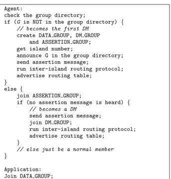
A1 A3 A4 A5 A2 B2 B1 F1 F3 F4 F2 C2 C1 D2 D1 E2 E1
Figure 5: Multi-DM model with shared-tree inter-island routing
as before, there will be duplicate packets and routing loops. In Fig. 4, suppose A3 multicasts a packet. The packet will use four exits, A1, A2, A4 and A5, to leave island A, as intended. But when it reaches island F, F1 and F2 each receives a copy, from D1 and E1 respectively. Both F1 and F2 will multicast the packet onto island F. Members in is-land F now receive two copies of the same packet. When the copy multicast by F2 reaches F1, F1 will forward it to D1, resulting in a routing loop and more duplicates. Therefore, multiple DMs within the same island should cooperate with each other to ensure that a packet enters the island only once and will be forwarded without forming a loop. We next look at several solutions contingent upon the type of inter-island routing protocol used.
3.2.3
Shared-Tree Inter-Island Routing
In protocols like BTP, HMTP, and Yoid a single tree struc-ture is built among all nodes and shared by all data sources. Multicast delivery is achieved by simply flooding the shared-tree. Though different protocols have different ways to con-struct the shared-tree, we are interested only in how to keep such a protocol working when each node is a multi-DM is-land, regardless of any specific protocol detail.
Our approach is to organize the DMs of each island into a two-level hierarchy, with one of the DMs serving asHead DM, and all the othersTail DMs. Head DM runs the inter-island end-host multicast protocol as usual to find its parent DM in other islands. Tail DMs, on the other hand, must always take the Head DM as their parent. In Fig. 5, A1 is the Head DM of island A, A2, A4 and A5 are Tail DMs, and B1 is the root of the inter-island shared-tree. From the other islands’ point of view, island A has only one parent (i.e., B1) and multiple children (i.e., C1, D1 and E1), just
Agent:
check the group directory;
if (G is NOT in the group directory) {
// becomes Head DM
create DATA GROUP, DM GROUP and ASSERTION GROUP;
announce G in the group directory; send assertion message;
send keepalive message;
run inter-island routing protocol; }
else {
join ASSERTION GROUP;
if (no assertion message is heard) {
// becomes a DM
send assertion message; join DM GROUP;
take Head DM as parent;
run inter-island routing protocol; }
// else just be a normal member
}
Application: Join DATA GROUP;
Figure 6: Join Group G (Shared-tree Routing)
as in the single-DM case. In this way, the tree structure is preserved going through a multi-DM island, and packet forwarding does not result in a loop. Suppose B1 sends a packet to A1. A1 will forward it to D1 through its unicast tunnel, as well as send it to the DATA GROUP in island A. A2 and A5 receive the IP multicast packet and forward it to C1 and E1 respectively. There will be no routing loop or packet duplication since all DMs form a shared-tree with both UDP tunnels and IP multicast.
Deciding which of the multiple DMs in an island becomes the Head DM requires coordination among the DMs, which is done via another IP multicast group, DM GROUP. Ini-tially, the first DM in an island becomes the Head DM (Fig. 6). The Head DM periodically sends out a keepalive message to the DM GROUP, advertising its existence. In the presence of multiple DMs in an island, the Head DM is dynamically elected, as follows. Every DM measures its round-trip time (rtt) to the Head DM’s parent (i.e., B1 in Fig. 5). The Head DM includes its rtt value in its keepalive messages. If a Tail DM has a smaller rtt than that adver-tised by the Head DM, it assumes the role of Head DM by sending its own keepalive message with the smaller rtt value. The result is that the Head DM is always the DM with the shortest rtt to the island’s parent. Suppose A4 in Fig. 5 is the first member in island A to join the multicast group. It assumes the role of Head DM for island A and adopts B1 as its parent in the inter-island end-host multicast proto-col. When A1 joins the group later, its joins as a Tail DM. Upon discovering that it is closer to B1 than A4, A1 will replace A4 as the new Head DM. To avoid oscillation, we introduce a hysteresis around the rtt values when changing Head DMs. Note that it is not a DM’s responsibility to find close-by children, instead each DM closest to the current parent becomes the Head DM of an island. After missing keepalive messages from the Head DM for several update periods, each Tail DM will schedule transmission of its own keepalive message, with a random delay. The first one to transmit its keepalive message becomes the new Head DM.
A1 A3 A4 A5 A2 B2 B1 F1 F3 F4 F2 C2 C1 D2 D1 E2 E1
Figure 7: Multi-DM model with source-tree inter-island routing
Agent:
check the group directory;
if (G is NOT in the group directory) {
// becomes the first DM
create DATA GROUP, DM GROUP and ASSERTION GROUP; get island number;
announce G in the group directory; send assertion message;
run inter-island routing protocol; advertise routing table;
}
else {
join ASSERTION GROUP;
if (no assertion message is heard) {
// becomes a DM
send assertion message; join DM GROUP;
run inter-island routing protocol; advertise routing table;
}
// else just be a normal member
}
Application: Join DATA GROUP;
Figure 8: Join Group G (source-tree routing)
3.2.4
Source-Tree Inter-Island Routing
When the end-host protocol used for inter-island multicast builds per-source tree instead of using a group-shared tree, the resulting inter-island topology is not an acyclic graph. Hence the above solution to construct an intra-island tree does not apply. Packet forwarding on per-source multicast topology depends on each node maintaining a routing table containing shortest paths to all data sources. These tables are exchanged between neighbors and packet forwarding is done by reverse path forwarding (RPF) based on the routing tables.
Under the single-DM model, each DM advertises its own IP address in its route updates. When forwarding packets to an island, the DM’s IP address is used by other nodes to identify the island. We need a similar globally unique identifier associated with each island in the multi-DM case. Instead of each DM in an island advertising its own IP ad-dress in its routing table, they must all use this globally unique identifier to identify the island. Under IP multi-cast, an island’s address prefix can be used as its globally unique identifier. Under end-host multicast, however, each
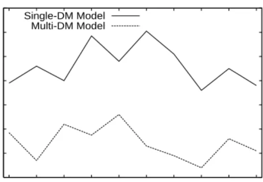
1.8 2 2.2 2.4 2.6 2.8 3 3.2 50 100 150 200 250 300 350 400 450 500 ARDP Island Size Single-DM Model Multi-DM Model
Figure 9: ARDP vs. Island Size (HMTP)
host usually does not know how large its island is, nor how many address prefixes its island encompasses. Our solution is to assign an island number per island. This number can be assigned by the rendezvous host, for example; the only requirement is that each island must have a unique identifier amongst all islands that form a multicast group.
A DM includes its island number in the group advertise-ment sent to the local group directory. In this way, members learn of the island’s number upon joining the group. The island number is used in inter-island route updates to iden-tify the island. For example, in Fig. 7, suppose the island are assigned numbers A, B, C, D, E, and F. E1’s routing table records the shortest path to island B as E-A-B, in-stead of E1-A5-A1-B1. DMs in an island use IP multicast (DM GROUP) to exchange routing tables and updates. In this way, for purposes of inter-island routing and packet for-warding, each island can be viewed as a single node repre-sented by its island number. For example, in Fig. 7, when A5 receives a multicast packet, it will forward it to E1 if the source island is D, but will not forward it at all if the source island is F. This problem and solution bear similarity to inter-domain routing on the Internet using BGP (Border Gateway Protocol), except that while iBGP (internal BGP) uses unicast to exchange route updates, we utilize IP multi-cast.
There is one problem with the above solution. Reverse Path Forwarding (RPF) relies on a packet’s source address in its operation. Under end-host multicast, however, the source address (source island number in this case) is carried in the encapsulation header of tunneled UDP packets. When a DM forwards a packet onto an island, the encapsulation header must be stripped off and only the application payload is sent onto the island. Without source island number, downstream DMs will not be able to apply RPF when they receive the multicast packet. One possible solution is to use IP option to carry the source island number. Applications still receive native IP multicast packets, but UM agents running in DMs consult this option to extract the source island number for RPF checking.
4.
SIMULATION
We conducted simulations to evaluate the performance gain of the multi-DM model over the single-DM model. We use the Internet AS map [3] to represent the inter-domain
1.8 1.9 2 2.1 2.2 2.3 2.4 2.5 2.6 2.7 2.8 50 100 150 200 250 300 350 400 450 500 ARDP Island Size Single-DM Model Multi-DM Model
Figure 10: ARDP vs. Island Size (Narada)
4 6 8 10 12 14 16 18 50 100 150 200 250 300 350 400 450 500
Worst Link Load
Island Size Single-DM Model
Multi-DM Model
Figure 11: Maximum Node Load vs. Island Size
(HMTP) 4 6 8 10 12 14 16 18 50 100 150 200 250 300 350 400 450 500
Worst Link Load
Island Size Single-DM Model
Multi-DM Model
Figure 12: Maximum Node Load vs. Island Size
(Narada)
topology. In each simulation, several ASs are randomly cho-sen as multicast islands. Each island is then populated with router network using the Waxman topology generator. Fi-nally, host nodes are randomly attached to routers as mul-ticast group members. The number of routers in an island varies from 50 to 500, but is the same for all islands per sim-ulation. The results presented here are from simulations of 100 islands with 20 group members in each island. For each physical network link, we assign delay uniformly between 3-10ms. We have also run simulations with other settings, obtaining qualitatively similar results.
Intra-island IP multicast routing assumed per-source short-est path tree similar to that used in DVMRP. For inter-island routing, we simulated two protocols: HMTP for shared-tree routing and Narada for source-shared-tree routing. In the single-DM model, the DM is randomly selected from mem-ber hosts, with uniform probability. In the multi-DM mode, half of the members in an island are randomly selected as DMs, again with uniform probability.5
We use two metrics in our performance evaluation: Av-erage Relative Delay Penalty (ARDP) and worst link load. Relative Delay Penalty (RDP) is the ratio of multicast delay to unicast delay between two nodes. ARDP is the average of RDP over all host pairs. The load of a node is the number of unicast tunnels it must support. For each simulation, we take the average of 100 runs and plot each data point with 95% confidence interval.
Figs. 9 and 10 show that as the island size increases, ARDPs under the single-DM case increases whereas those under the multi-DM case actually decreases. We attribute this to the increasing significance of intra-island latency as the island size increases. The multi-DM model can factor out large intra-island delays in inter-island latencies. This is true for both inter-island routing protocols we have sim-ulated. Figs. 11 and 12 show that while having multiple DMs per island clearly reduces the maximum node load, for the scenarios simulated the effect of island size on maximum node load is not apparent.
We have implemented a prototype of the UM framework and are evaluating its performance with existing applica-tions.
5.
SUMMARY
In response to the slow deployment of IP multicast and the urgent need of applications for multicast delivery, end-host multicast protocols have been proposed to move multicast functionality from routers to end hosts. As a basic service common to most group communication applications, multi-cast may be best implemented as part of the network infras-tructure, in terms of performance and scalability. However, from the deployment point of view, the path of least resis-tance is to evolve from network edges toward network core. Universal Multicast is designed to leverage both router-level and end-host multicast paradigms to achieve a better trade-5Clearly we do not expect half of an island’s population to serve as DMs. Since in our simulations DM that are not very well placed, performance-wise, will not be selected by the end-host multicast protocol to be on the inter-island mul-ticast tree, their existence does not effect the performance metrics studied. It does mean, however, that the perfor-mance numbers reported correspond to cases in which we can find well-placed hosts to serve as DMs. This is a topic of our future work.
off between performance/scalability and deployability. Un-der this framework, a node in an end-host multicast tree can be expanded to encompass an IP multicast island. The system is fully distributed and self-organized, without re-quiring any multicast support from routers, servers, tunnel-points, or operating systems. Nonetheless, the designwill take advantage of all available network and system support for native multicast. In this paper, we propose a novel model that utilizes multiple Designated Members per IP multicast island in inter-island multicast routing. This model allows us to reduce delivery latency and traffic concentration in large islands. It is conceivable that the deployment of mul-ticast service on the Internet will take several stages, from pure end-host based to server/proxy supported, from LAN IP multicast to intra-domain and inter-domain IP multi-cast, from MBGP/MSDP to MASC/BGMP etc. Universal Multicast is not designed for a specific deployment stage, but as a general framework within which applications can be provided with ubiquitous IP multicast delivery immedi-ately, giving network providers incentive to deploy native multicast more widely.
6.
ACKNOWLEDGMENTS
We thank Vasileios Pappas for his work on the implemen-tation of UM and the anonymous reviewers for their helpful comments.
7.
REFERENCES
[1] S. Banerjee, B. Bhattacharjee, and C. Kommareddy. Scalable application layer multicast. InProc. of ACM SIGCOMM, Sept. 2002.
[2] Y. Chawathe, S. McCanne, and E. Brewer. An architecture for Internet content distribution as an infrastructure service.
http://www.cs.berkeley.edu/˜ yatin/papers/scattercast.ps. [3] Q. Chen, H. Chang, R. Govindan, S. Jamin,
S. Shenker, and W. Willinger. The origin of power-laws in Internet topologies revisited. InIEEE INFOCOM, June 2002.
[4] Y. Chu, S. G. Rao, and H. Zhang. A case for end system multicast. InProc. of ACM SIGMETRICS, pages 1–12, June 2000.
[5] L. H. M. K. Costa, S. Fdida, and O. C. M. B. Duarte. Hop by hop multicast routing protocol. InProc. of ACM SIGCOMM, Sept. 2001.
[6] S. Deering and D. Cheriton. Multicast routing in datagram internetworks and extended LANs.ACM Transactions on Computer Systems, 8(2):85–110, May 1990.
[7] W. Fenner. Internet group management protocol, version 2. RFC 2236, IETF, Nov. 1997.
[8] P. Francis. Yoid: your own Internet distribution. http://www.isi.edu/div7/yoid/, Mar. 2001.
[9] M. Handley. Session directories and scalable Internet multicast address allocation.ACM Computer Communication Review, 28(4):105–116, Sept. 1998. [10] D. Helder and S. Jamin. End-host multicast
communication using switch-trees protocols. InGlobal and Peer-to-Peer Computing on Large Scale
Distributed Systems (GP2PC), May 2002.
[11] H. Holbrook and B. Cain. Source-specific multicast for IP. Internet Draft, IETF, Nov. 2000.
[12] J. Liebeherr and T. Beam. HyperCast: A Protocol for Maintaining Multicast Group Members in a Logical Hypercube Topology. InNetworked Group
Communication, pages 72–89, 1999.
[13] D. Pendarakis, S. Shi, D. Verma, and M. Waldvogel. ALMI: an application level multicast infrastructure. In Proceedings of 3rd Usenix Symposium on Internet Technologies and Systems (USITS 2001), Mar. 2001. [14] R. Perlman, C. Lee, T. Ballardie, J. Crowcroft,
Z. Wang, T. Maufer, C. Diot, J. Thoo, and M. Green. Simple multicast: a design for simple, low-overhead multicast. Internet Draft, IETF, Mar. 1999. [15] S. Shi and J. Turner. Routing in overlay multicast
networks. InProc. of IEEE INFOCOM 2002, June 2002.
[16] I. Stoica, T. S. E. Ng, and H. Zhang. REUNITE: a recursive unicast approach to multicast. InProc. of IEEE INFOCOM 2000, Mar. 2000.
[17] W. Wang, D. Helder, S. Jamin, and L. Zhang. Overlay optimizations for end-host multicast. InProc. of the Int’l Workshop on Networked Group Communication (NGC), Oct. 2002.
[18] B. Zhang, S. Jamin, and L. Zhang. Host Multicast: a framework for delivering multicast to end users. In Proc. of IEEE INFOCOM 2002, June 2002.