CHAPTER 1
Introducing Network Design Concepts
Objectives
Upon completion of this chapter, you should be able to answer the following questions: ■ What are the benefits of a hierarchal network
design?
■ What is the design methodology used by network designers?
■ What are the design considerations for the core, distribution, and access layers?
■ What are the design considerations for the network enterprise edge?
■ What are the design considerations that must be met to support remote workers?
■ What are the design considerations for supporting enterprise wireless and/or data center/server farms?
Key Terms
This chapter uses the following key terms. You can find the definitions in the Glossary.
Cisco Enterprise Architectures page 5
deterministic network page 5
top-down approach page 7
content networking page 8
storage networking page 8
network backbone page 9
virtual private networks (VPN) page 9
extranet page 9
multilayer switches page 11
load balancing page 11
Enhanced Interior Gateway Routing Protocol (EIGRP) page 11
Open Shortest Path First (OSPF) Protocol page 11
Spanning Tree Protocol (STP) page 11
full-mesh page 11
partial-mesh page 11
hot-swappable page 13
uninterruptible power supply (UPS) page 13
convergence time page 14
switch block page 17
Rapid Spanning Tree Protocol (RSTP) page 18
access control lists (ACL) page 19
dynamic ACL page 20
reflexive ACL page 20
time-based ACL page 20
Intermediate System-to-Intermediate System (IS-IS) Protocol page 21
Power-over-Ethernet (PoE) page 23
failover page 24
network access control page 30
security policy page 30
server farms page 30
data centers page 30
storage-area networks (SAN) page 32
denial-of-service (DoS) page 32
demilitarized zone (DMZ) page 33
Rapid Spanning Tree Protocol Plus (RSTP+) page 34
wireless LAN (WLAN) page 34
Wired Equivalent Privacy (WEP) page 37
Wi-Fi Protected Access (WPA) page 37
service set identifier (SSID) page 37
cell-switched networks page 40
Asynchronous Transfer Mode (ATM) page 40
Network designers ensure that our communications networks can adjust and scale to the demands for new services.
To support our network-based economy, designers must work to create networks that are available nearly 100 percent of the time.
Information network security must be designed to automatically fend off unexpected security incidents. Using hierarchical network design principles and an organized design methodology, designers create networks that are both manageable and supportable.
Discovering Network Design Basics
The sections that follow cover the basics of network design with regard to the following concepts:
■ Network design overview
■ The benefits of a hierarchical network design ■ Network design methodology
Network Design Overview
Computers and information networks are critical to the success of businesses, both large and small. They connect people, support applications and services, and provide access to the resources that keep the businesses running. To meet the daily requirements of businesses, networks themselves are becom-ing quite complex.
Network Requirements
Today, the Internet-based economy often demands around-the-clock customer service. This means that business networks must be available nearly 100 percent of the time. They must be smart enough to automatically protect against unexpected security incidents. These business networks must also be able to adjust to changing traffic loads to maintain consistent application response times. It is no longer practical to construct networks by connecting many standalone components without careful planning and design.
Building a Good Network
Good networks do not happen by accident. They are the result of hard work by network designers and technicians, who identify network requirements and select the best solutions to meet the needs of a business.
The steps required to design a good network are as follows:
Step 1. Verify the business goals and technical requirements.
Step 2. Determine the features and functions required to meet the needs identified in Step 1.
Step 3. Perform a network-readiness assessment.
Step 4. Create a solution and site acceptance test plan.
Step 5. Create a project plan.
After the network requirements have been identified, the steps to designing a good network are fol-lowed as the project implementation moves forward.
Network users generally do not think in terms of the complexity of the underlying network. They think of the network as a way to access the applications they need, when they need them.
Network Requirements
Most businesses actually have only a few requirements for their network:
■ The network should stay up all the time, even in the event of failed links, equipment failure, and overloaded conditions.
■ The network should reliably deliver applications and provide reasonable response times from any host to any host.
■ The network should be secure. It should protect the data that is transmitted over it and data stored on the devices that connect to it.
■ The network should be easy to modify to adapt to network growth and general business changes. ■ Because failures occasionally occur, troubleshooting should be easy. Finding and fixing a problem
should not be too time-consuming.
Fundamental Design Goals
When examined carefully, these requirements translate into four fundamental network design goals:
■ Scalability: Scalable network designs can grow to include new user groups and remote sites and can support new applications without impacting the level of service delivered to existing users.
■ Availability: A network designed for availability is one that delivers consistent, reliable perform-ance, 24 hours a day, 7 days a week. In addition, the failure of a single link or piece of equipment should not significantly impact network performance.
■ Security: Security is a feature that must be designed into the network, not added on after the net-work is complete. Planning the location of security devices, filters, and firewall features is critical to safeguarding network resources.
■ Manageability: No matter how good the initial network design is, the available network staff must be able to manage and support the network. A network that is too complex or difficult to maintain cannot function effectively and efficiently.
The Benefits of a Hierarchical Network Design
To meet the four fundamental design goals, a network must be built on an architecture that allows for both flexibility and growth.
Hierarchical Network Design
In networking, a hierarchical design is used to group devices into multiple networks. The networks are organized in a layered approach. The hierarchical design model has three basic layers:
■ Core layer: Connects distribution layer devices
■ Distribution layer: Interconnects the smaller local networks
Hierarchical networks have advantages over flat network designs. The benefit of dividing a flat network into smaller, more manageable hierarchical blocks is that local traffic remains local. Only traffic destined for other networks is moved to a higher layer.
Layer 2 devices in a flat network provide little opportunity to control broadcasts or to filter undesirable traffic. As more devices and applications are added to a flat network, response times degrade until the network becomes unusable. Figures 1-1 and 1-2 show the advantages of a hierarchical network design versus a flat network design.
Figure 1-1 Flat Network
Flat Switched Network
One Large Broadcast Domain
Hierarchical Network
Core
Access Distribution
Three Separate Broadcast Domains
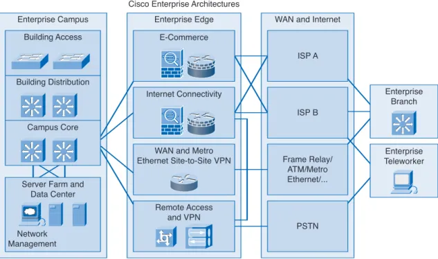
Modular Design of Cisco Enterprise Architectures
The Cisco Enterprise Architectures(see Figure 1-3) can be used to further divide the three-layer hier-archical design into modular areas. The modules represent areas that have different physical or logical connectivity. They designate where different functions occur in the network. This modularity enables flexibility in network design. It facilitates implementation and troubleshooting. Three areas of focus in modular network design are as follows:
■ Enterprise campus: This area contains the network elements required for independent operation within a single campus or branch location. This is where the building access, building distribu-tion, and campus core are located.
■ Server farm: A component of the enterprise campus, the data center server farm protects the server resources and provides redundant, reliable high-speed connectivity.
■ Enterprise edge: As traffic comes into the campus network, this area filters traffic from the exter-nal resources and routes it into the enterprise network. It contains all the elements required for efficient and secure communication between the enterprise campus and remote locations, remote users, and the Internet.
Figure 1-3 Cisco Enterprise Architectures
Enterprise Teleworker Enterprise Branch Enterprise Edge WAN and Internet
ISP A ISP B Frame Relay/ ATM/Metro Ethernet/... PSTN Cisco Enterprise Architectures
E-Commerce
Internet Connectivity
WAN and Metro Ethernet Site-to-Site VPN Remote Access and VPN Enterprise Campus Building Access Building Distribution Campus Core
Server Farm and Data Center
Network Management
The modular framework of the Cisco Enterprise Architectures as depicted in Figure 1-4 has the following design advantages:
■ It creates a deterministic networkwith clearly defined boundaries between modules. This provides clear demarcation points so that the network designer knows exactly where the traffic originates and where it flows.
■ It eases the design task by making each module independent. The designer can focus on the needs of each area separately.
■ It provides scalability by allowing enterprises to add modules easily. As network complexity grows, the designer can add new functional modules.
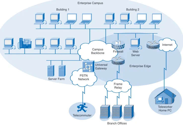
■ It enables the designer to add services and solutions without changing the underlying network design. Figure 1-4 Enterprise Campus
IP Teleworker Home PC Frame Relay PSTN Network Campus Backbone Internet Telecommuter Router Universal Gateway Server Farm Building 1 Building 2 Enterprise Edge Enterprise Campus Firewall Web Server Branch Offices Router
Interactive Activity 1-1: Match the Characteristics of the Hierarchal Model and the Cisco Enterprise Architecture (1.1.2)
In this interactive activity, you match the characteristics of the hierarchal model and the Cisco Enterprise Architecture to their correct location. Use file ia-112 on the CD-ROM that accompanies this book to perform this interactive activity.
Network Design Methodologies
Large network design projects are normally divided into three distinct steps:
Step 1. Identify the network requirements.
Step 2. Characterize the existing network.
Step 1: Identifying Network Requirements
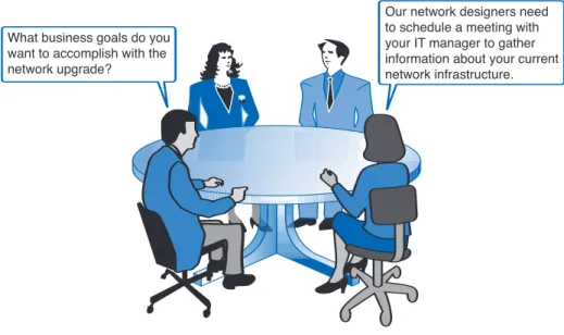
The network designer works closely with the customer to document the goals of the project. Figure 1-5 depicts a meeting between the designer and the business owner. Goals are usually separated into two categories:
■ Business goals: Focus on how the network can make the business more successful
■ Technical requirements: Focus on how the technology is implemented within the network
Step 2: Characterizing the Existing Network
Information about the current network and services is gathered and analyzed. It is necessary to compare the functionality of the existing network with the defined goals of the new project. The designer determines whether any existing equipment, infrastructure, and protocols can be reused, and what new equipment and protocols are needed to complete the design.
Step 3: Designing the Network Topology
A common strategy for network design is to take a top-down approach. In this approach, the network applications and service requirements are identified, and then the network is designed to support them. When the design is complete, a prototype or proof-of-concept test is performed. This approach
ensures that the new design functions as expected before it is implemented.
Figure 1-5 Client Interaction
What business goals do you want to accomplish with the network upgrade?
Our network designers need to schedule a meeting with your IT manager to gather information about your current network infrastructure.
A common mistake made by network designers is the failure to correctly determine the scope of the network design project.
Determining the Scope of the Project
While gathering requirements, the designer identifies the issues that affect the entire network and those that affect only specific portions. By creating a topology similar to Figure 1-6, the designer can isolate areas of concern and identify the scope of the project. Failure to understand the impact of a particular requirement often causes a project scope to expand beyond the original estimate. This oversight can greatly increase the cost and time required to implement the new design.
Figure 1-6 Enterprise Campus IP Teleworker Home PC Frame Relay PSTN Network Campus Backbone Internet Telecommuter Router Universal Gateway Server Farm Building 1 Building 2 Enterprise Edge Enterprise Campus Firewall Web Server Branch Offices Router
Impacting the Entire Network
Network requirements that impact the entire network include the following:
■ Adding new network applications and making major changes to existing applications, such as database or Domain Name System (DNS) structure changes
■ Improving the efficiency of network addressing or routing protocol changes ■ Integrating new security measures
■ Adding new network services, such as voice traffic,content networking, and storage networking ■ Relocating servers to a data center server farm
Impacting a Portion of the Network
Requirements that may only affect a portion of the network include the following:
■ Improving Internet connectivity and adding bandwidth ■ Updating access layer LAN cabling
■ Providing redundancy for key services ■ Supporting wireless access in defined areas ■ Upgrading WAN bandwidth
Interactive Activity 1-2: Determining the Project Scope (1.1.3)
In this interactive activity, you determine whether each of the requirements affects the entire network or only a portion of the network. Use file ia-113 on the CD-ROM that accompanies this book to perform this interactive activity.
Investigating Core Layer Design Considerations
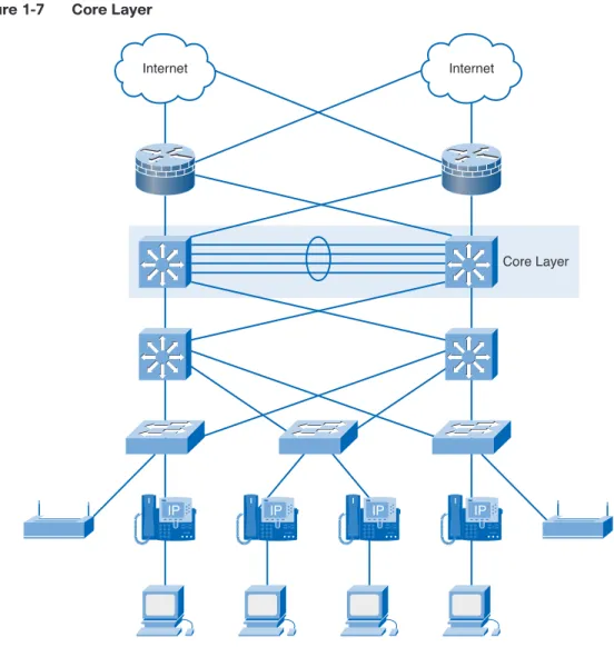
The Cisco three-layer hierarchal model is composed of the core layer, distribution layer, and access layer. Of the three layers, the core layer is responsible for transporting large amounts of data quickly and reliably. The designer must ensure that the core layer is designed with fault tolerance, especially because all users in the network can be affected by a failure. The ability to avoid unnecessary delays in network traffic quickly becomes a top priority for the network designer.What Happens at the Core Layer?
The core layer is sometimes called the network backbone. Routers and switches at the core layer provide high-speed connectivity. In an enterprise LAN, the core layer, shown in Figure 1-7, may connect multiple buildings or multiple sites, and may provide connectivity to the server farm. The core layer includes one or more links to the devices at the enterprise edge to support Internet,virtual private networks (VPN),extranet, and WAN access.
Figure 1-7 Core Layer
IP IP IP IP
Core Layer Internet
Internet
Implementing a core layer reduces the complexity of the network, making it easier to manage and troubleshoot.
Goals of the Core Layer
The core layer design enables the efficient, high-speed transfer of data between one section of the network and another. The primary design goals at the core layer are as follows:
■ Provide 100% uptime. ■ Maximize throughput. ■ Facilitate network growth.
Core Layer Technologies
Technologies used at the core layer include the following:
■ Routers or multilayer switchesthat combine routing and switching in the same device ■ Redundancy and load balancing
■ High-speed and aggregate links
■ Routing protocols that scale well and converge quickly, such as Enhanced Interior Gateway Routing Protocol (EIGRP)and Open Shortest Path First (OSPF) Protocol
Redundant Links
Implementing redundant links at the core layer ensures that network devices can find alternate paths to send data in the event of a failure. When Layer 3 devices are placed at the core layer, these redundant links can be used for load balancing in addition to providing backup. In a flat, Layer 2 network design,Spanning Tree Protocol (STP)disables redundant links unless a primary link fails. This STP behavior prevents load balancing over the redundant links.
Mesh Topology
Most core layers in a network are wired in either a full-meshor partial-meshtopology. A full-mesh topology is one in which every device has a connection to every other device (see Figure 1-8). Although full-mesh topologies provide the benefit of a fully redundant network, they can be difficult to wire and manage and are more costly. For larger installations, a modified partial-mesh topology is used. In a partial-mesh topology, each device is connected to at least two others, creating sufficient redundancy without the complexity of a full mesh.
Figure 1-8 Redundancy in a Mesh Topology
•• •• •• •• •• •• •• •• •• •• •• •• •• •• •• •• •• •• •• •• •• •• •• •• •• •• •• •• •• •• •• •• •• •• •• •• •• •• •• •• •• •• •• •• •• •• •• ••
Building Building
Redundancy in a Mesh Topology
Building •• • ••• • • • • • • • • • • • • • • • • • • • • • • • • • • • • • • • • •• • ••• ••• ••• ••• ••• ••• ••• ••• ••• ••• ••• ••• ••• Gigabit Ethernet or Gigabit EtherChannel
Ethernet or FastEthernet • • • • • •
Access
Server Farm Server Farm
Layer 3 Switched Backbone Layer 3 Switch Layer 2 Switch Distribution Core
Comparing Mesh Topologies (1.2.1)
In this activity, you create and compare full-mesh and partial-mesh topologies between routers. Use file d4-121.pka on the CD-ROM that accompanies this book to perform this activity using Packet Tracer.
Network Traffic Prioritization
Failures at the core layer can potentially affect all users of the network. Therefore, preventing failures becomes a daunting task. The network designer has to incorporate features or additions to the design to minimize or eliminate the effects of a core layer failure. The users on a network do not want to wait to complete their daily tasks because of a lack of care in the design.
Preventing Failures
The network designer must strive to provide a network that is resistant to failures and that can recover quickly in the event of a failure. Core routers and switches can contain the following:
■ Dual power supplies and fans ■ A modular chassis-based design ■ Additional management modules Packet Tracer
Redundant components increase the cost, but they are usually well worth the investment. Core layer devices should have hot-swappablecomponents whenever possible. Hot-swappable components can be installed or removed without first having to turn off the power to the device. Using these components reduces repair time and disruption to network services.
Larger enterprises often install generators and large uninterruptible power supply (UPS)devices. These devices prevent minor power outages from causing large-scale network failures.
Reducing Human Error
Human errors contribute to network failures. Unfortunately, the addition of redundant links and equipment cannot eliminate these factors. Many network failures are the result of poorly planned, untested updates or additions of new equipment. Never make a configuration change on a production network without first testing it in a lab environment! Figure 1-9 shows the percentages of common network outages.
Figure 1-9 Causes of Network Outages
20% Environmental Factors, HW, OS,
Power, Disasters Causes of Network Outages
40% Human Errors
40% Application Failures
Source: Gartner; Copyright © 2001
Failures at the core layer cause widespread outages. It is critical to have written policies and proce-dures in place to govern how changes are approved, tested, installed, and documented. Plan a back-out strategy to return the network to its previous state in case changes are not successful.
Network Convergence
The choice of a routing protocol for the core layer is determined by the size of the network and the number of redundant links or paths available. A major factor in choosing a protocol is how quickly it recovers from a link or device failure.
Convergence Definition and Factors
Network convergence occurs when all routers have complete and accurate information about the net-work. The faster the convergence time, the quicker a network can react to a change in topology. Factors that affect convergence time include the following:
■ The speed at which the routing updates reach all the routers in the network
■ The time that it takes each router to perform the calculation to determine the best paths
Selecting a Routing Protocol for Acceptable Convergence Time
Most dynamic routing protocols offer acceptable convergence times in small networks. In larger net-works, protocols such as Routing Information Protocol Version 2 (RIPv2) may converge too slowly to prevent disruption of network services if a link fails. Generally, in a large enterprise network, EIGRP or OSPF provide the most stable routing solution.
Design Considerations with Convergence in Mind
Most networks contain a combination of dynamic and static routes. Network designers need to consid-er the numbconsid-er of routes required to ensure that all destinations in the network are reachable. Large routing tables can take significant time to converge. The design of network addressing and summariza-tion strategies in all layers affects how well the routing protocol can react to a failure.
Observing Network Convergence (1.2.3)
In this activity, you use the existing topology and add a new LAN segment to observe network convergence. Use file d4-123.pka on the CD-ROM that accompanies this book to perform this activity using Packet Tracer.
Investigating Distribution Layer Design
Considerations
The next layer of the Cisco hierarchical model is the distribution layer. This layer is associated with routing, filtering, and is the communication point between the core layer and the access layer. A network designer must create a distribution layer design that complements the needs of the other two layers.
What Happens at the Distribution Layer?
The distribution layer represents a routing boundary between the access layer and the core layer. It also serves as a connection point between remote sites and the core layer.
Distribution Layer Routing
The access layer is commonly built using Layer 2 switching technology. The distribution layer (see Figure 1-10) is built using Layer 3 devices. Routers or multilayer switches, located at the distribution layer, provide many functions critical for meeting the goals of the network design, including the following:
■ Filtering and managing traffic flows ■ Enforcing access control policies Packet Tracer
■ Summarizing routes before advertising the routes to the Core ■ Isolating the core from access layer failures or disruptions ■ Routing between access layer VLANs
Distribution layer devices are also used to manage queues and prioritize traffic before transmission through the campus core.
Figure 1-10 Distribution Layer
Distribution IP IP IP IP Core Internet Internet Access
Trunks
Trunk links are often configured between access and distribution layer networking devices. Trunks are used to carry traffic that belongs to multiple VLANs between devices over the same link. The network designer considers the overall VLAN strategy and network traffic patterns when designing the trunk links.
Redundant Links
When redundant links exist between devices in the distribution layer, the devices can be configured to load balance the traffic across the links. Figure 1-11 shows the redundant links at the distribution layer. Load balancing is another option that increases the bandwidth available for applications.
Figure 1-11 Redundancy at the Distribution Layer Trunk and Redundant Links Distribution IP IP IP IP Core Internet Internet Access Packet Tracer Activity
Distribution Layer Topology
Distribution layer networks are usually wired in a partial-mesh topology. This topology provides enough redundant paths to ensure that the network can survive a link or device failure. When the dis-tribution layer devices are located in the same wiring closet or data center, they are interconnected using gigabit links. When the devices are separated by longer distances, fiber cable is used. Switches that support multiple high-speed fiber connections can be expensive, so careful planning is necessary to ensure that enough fiber ports are available to provide the desired bandwidth and redundancy.
Demonstrating Distribution Layer Functions (1.3.1)
In this activity, you demonstrate the functions performed by the distribution layer devices. Use file d4-131 on the CD-ROM that accompanies this book to perform this activity using Packet Tracer.
Limiting the Scope of Network Failure
A failure domain defines the portion of the network affected when either a device or network application fails.
Limiting the Size of Failure Domains
Because failures at the core layer of a network have a large impact, the network designer often concentrates on efforts to prevent failures. These efforts can greatly increase the cost to implement the network. In the hierarchical design model, it is easiest and usually least expensive to control the size of a failure domain in the distribution layer. In the distribution layer, network errors can be contained to a smaller area, thus affecting fewer users. When using Layer 3 devices at the distribution layer, every router functions as a gateway for a limited number of access layer users. Figure 1-12 shows the manner in which redundant cabling and devices can be configured to limit the effects of a link or device failure.
Figure 1-12 Protection Against Single Device Failures
Distribution Layer Distribution Layer Access Layer Core Layer Data Center Access Layer
Switch Block Deployment
Routers, or multilayer switches, are usually deployed in pairs, with access layer switches evenly divided between them. This configuration is referred to as a building or departmental switch block. Each switch blockacts independently of the others. As a result, the failure of a single device does not cause the network to go down. Even the failure of an entire switch block does not impact a significant number of end users.
Investigating Failure Domains (1.3.2)
In this activity, you turn off the devices and disable interfaces to see the resulting network failures. Use file d4-132.pka on the CD-ROM that accompanies this book to perform this activity using Packet Tracer.
Building a Redundant Network at the Distribution Layer
To reduce downtime, the network designer deploys redundancy in the network.
Devices at the distribution layer have redundant connections to switches at the access layer and to devices at the core layer. If a link or device fails, these connections provide alternate paths. Using an appropriate routing protocol at the distribution layer, the Layer 3 devices react quickly to link failures so that they do not impact network operations.
Providing multiple connections to Layer 2 switches can cause unstable behavior in a network unless STP is enabled. Without STP (see Figure 1-13), redundant links in a Layer 2 network can cause broadcast storms. Switches are unable to correctly learn the ports, so traffic ends up being flooded throughout the switch. By disabling one of the links, STP guarantees that only one path is active between two devices (see Figure 1-14). If one of the links fails, the switch recalculates the spanning-tree topology and automatically begins using the alternate link.
Rapid Spanning Tree Protocol (RSTP), as defined in IEEE 802.1w, builds upon the IEEE 802.1d technology and provides rapid convergence of the spanning tree.
Figure 1-13 Traffic Patterns Without STP Packet Tracer
Activity
Broadcast packet from PC1.
Network with a loop, broadcasts are flooded. PC1
Figure 1-14 Traffic Patterns with STP
One port blocked by STP eliminates loop and stops flooding of broadcasts. Broadcast packet
from PC1.
PC1
Consider the case in which a high-volume, enterprise server is connected to a switch port. If that port recalculates because of STP, the server is down for 50 seconds. It would be difficult to imagine the number of transactions lost during that timeframe.
In a stable network, STP recalculations are infrequent. In an unstable network, it is important to check the switches for stability and configuration changes. One of the most common causes of frequent STP recalculations is a faulty power supply or power feed to a switch. A faulty power supply causes the device to reboot unexpectedly.
Traffic Filtering at the Distribution Layer
Access control lists (ACL)are a tool that can be used at the distribution layer to limit access and to prevent unwanted traffic from entering the core network. An ACL is a list of conditions used to test network traffic that attempts to travel through a router interface. ACL statements identify which packets to accept or which to deny.
Filtering Network Traffic
To filter network traffic, the router examines each packet and then either forwards or discards it, based on the conditions specified in the ACL. There are different types of ACLs for different purposes. Standard ACLs filter traffic based on the source address. Extended ACLs can filter based on multiple criteria, including the following:
■ Source address ■ Destination address ■ Protocols
■ Port numbers or applications
■ Whether the packet is part of an established TCP stream
Complex ACLs
Standard and extended ACLs serve as the basis for other, more complex types of ACLs. With Cisco IOS Software, you can configure three complex ACL features:
■ Dynamic ACL: Requires a user to use telnet to connect to the router and authenticate. Once authenticated, traffic from the user is permitted. Dynamic ACLs are sometimes referred to as “lock and key” because the user is required to log in to obtain access.
■ Reflexive ACL: Allows outbound traffic and then limits inbound traffic to only responses to those permitted requests. This is similar to the established keyword used in extended ACL statements, except that these ACLs can also inspect User Datagram Protocol (UDP) and Internet Control Message Protocol (ICMP) traffic, in addition to TCP.
■ Time-based ACL: Permits and denies specified traffic based on the time of day or day of the week.
Placing ACLs
Traffic that travels into an interface is filtered by the inbound ACL. Traffic going out of an interface is filtered by the outbound ACL. The network designer must decide where to place ACLs within the network to achieve the desired results.
It is important to remember the following rules for designing and applying ACLs:
■ There can be one ACL per protocol per direction per interface. ■ Standard ACLs should be applied closest to the destination. ■ Extended ACLs should be applied closest to the source.
■ The inbound or outbound interface should be referenced as if looking at the port from inside the router.
■ Statements are processed sequentially from the top of the list to the bottom until a match is found. If no match is found, the packet is denied and discarded.
■ There is an implicit “deny any” at the end of all ACLs. This statement does not appear in the configuration listing.
■ The network administrator should configure ACL entries in an order that filters from specific to general. Specific hosts should be denied first, and groups or general filters should come last.
■ The match condition is examined first. The “permit” or “deny” is examined only if the match is true. ■ Never work with an ACL that is actively applied.
■ Use a text editor to create comments that outline the logic. Then fill in the statements that perform the logic.
■ The default behavior is that new lines are always added to the end of the ACL. Ano access-listx command removes the whole list.
■ An IP access control list sends an ICMP host unreachable message to the sender of the rejected packet and discards the packet in the bit bucket.
■ An ACL should be removed carefully. Removing an access list immediately stops the filtering process.
■ Outbound filters do not affect traffic that originates from the local router.
Interactive Activity 1-3: Match ACLs to the Appropriate Statements (1.3.4)
In this interactive activity, you determine which ACL has been applied to the correct statement. Use file ia-134 on the CD-ROM that accompanies this book to perform this interactive activity.
Placing ACLs (1.3.4)
In this activity, you place the ACLs onto the appropriate interface in the topology. Use file d4-134.pka on the CD-ROM that accompanies this book to perform this activity using Packet Tracer.
Lab 1-1: Creating an ACL (1.3.4)
In this lab, you create an ACL to meet the conditions specified in the lab. Refer to the hands-on lab in Part II of this Learning Guide. You may perform this lab now or wait until the end of the chapter.
Routing Protocols at the Distribution Layer (1.3.5)
Another important function that occurs at the distribution layer is route summarization, also called route aggregation or supernetting.
Route Summarization
Route summarization has several advantages for the network, such as the following:
■ One route in the routing table that represents many other routes, creating smaller routing tables ■ Less routing update traffic on the network
■ Lower overhead on the router
Summarization can be performed manually or automatically, depending on which routing protocols are used in the network.
Classless routing protocols such as RIPv2, EIGRP, OSPF, and Intermediate System-to-Intermediate System (IS-IS) Protocolsupport route summarization based on subnet addresses on any boundary. Classful routing protocols such as RIPv1 automatically summarize routes on the classful network boundary, but do not support summarization on any other boundaries.
Figure 1-15 shows information on individual and summarized routes. Packet Tracer
Figure 1-15 Individual and Summarized Routes Fa0/0 Up date R1 R3 R2 172.16.0.0/16 172.17.0.0/16 Fa0/0 Fa0/0 Fa0/1 S0/0/0 S0/0/1DCE S0/0/0 DCE Classless Routing 172.19.0.0/16 10.1.0.0/16 172.18.0.0/16 Individual Routes 172.16.0.0/16 172.17.0.0/16 172.18.0.0/16 172.19.0.0/16 Summary Routes 172.16.0.0/14 S0/0/1
Interactive Activity 1-4: Identify Summary Routes (1.3.5)
In this interactive activity, you select the appropriate summary route from the distribution router to the core in a given topology. Use file ia-135 on the CD-ROM that accompanies this book to perform this interactive activity.
Investigating Access Layer Design Considerations
The access layer is used to control user access to the internetwork resources. The network designer has to facilitate the traffic generated from the access layer as it is bound for other segments or other layers within the network. Without an appropriate design, the access layer could quickly become inundated with traffic, resulting in less-than-acceptable performance for the end users.What Happens at the Access Layer?
The access layer, as illustrated in Figure 1-16, represents the edge of the network where end devices connect. Access layer services and devices reside inside each building of a campus, each remote site and server farm, and at the enterprise edge.
Figure 1-16 Access Layer Distribution Layer IP IP IP IP Core Layer Internet Internet Access Layer
Access Layer Physical Considerations
The access layer of the campus infrastructure uses Layer 2 switching technology to provide access into the network. The access can be either through a permanent wired infrastructure or through wire-less access points. Ethernet over copper wiring poses distance limitations. Therefore, one of the pri-mary concerns when designing the access layer of a campus infrastructure is the physical location of the equipment.
Wiring Closets
Wiring closets can be actual closets or small telecommunication rooms that act as the termination point for infrastructure cabling within buildings or within floors of a building. The placement and physical size of the wiring closets depends on network size and expansion plans.
The wiring closet equipment provides power to end devices such as IP phones and wireless access points. Many access layer switches have Power-over-Ethernet (PoE)functionality.
Unlike a typical wiring closet, inside a server farm or data center the access layer devices are typically redundant multilayer switches that combine the functionality of both routing and switching. Multilayer switches can provide firewall and intrusion protection features and Layer 3 functions.
The Impact of Converged Networking at the Access Layer
The modern computer network consists of more than just personal computers and printers connecting to the access layer. Many different devices, as shown in Figure 1-17, can connect to an IP network, including the following:
■ IP telephones ■ Video cameras
■ Videoconferencing systems
Figure 1-17 Access Layer Connections
Access Layer Connections
1-58713-212-5 ds330117.eps 02/25/08
ICC Macmillan Inc.
All of these services can be converged onto a single physical access layer infrastructure. However, the logical network design to support them becomes more complex because of considerations such as quality of service (QoS), traffic segregation, and filtering. These new types of end devices, and the associated applications and services, change the requirements for scalability, availability, security, and manageability at the access layer.
The Need for Availability at the Access Layer
In early networks, high availability was usually present only at the network core, enterprise edge, and data center networks. With IP telephony, there is now an expectation that every individual telephone should be available 100 percent of the time.
Redundant components and failoverstrategies can be implemented at the access layer to improve reliability and increase availability for the end devices.
Access Layer Management
Improving the manageability of the access layer is a major concern for the network designer. Access layer management is crucial because of the following:
■ The increase in the number and types of devices connecting at the access layer ■ The introduction of wireless access points into the LAN
Designing for Manageability
In addition to providing basic connectivity at the access layer, the designer needs to consider the following:
■ Naming structures ■ VLAN architecture ■ Traffic patterns
■ Prioritization strategies
Configuring and using network management systems for a large converged network are very important. Figure 1-18 shows an example of network management software. It is also important to standardize configurations and equipment when possible.
Figure 1-18 Network Management Software: Cisco Assistant
Following good design principles improves the manageability and ongoing support of the network by
■ Ensuring that the network does not become too complex ■ Allowing easy troubleshooting when a problem occurs ■ Making it easier to add new features and services in the future
Exploring Access Layer Functions (1.4.1)
In this activity, you explore different access layer functions. Use file d4-141.pka on the CD-ROM that accompanies this book to perform this activity using Packet Tracer.
Packet Tracer Activity
Network Topologies at the Access Layer
Most recent Ethernet networks use a star topology, which is sometimes called a hub-and-spoke topolo-gy. In a star topology, each end device has a direct connection to a single networking device. This sin-gle networking device is usually a Layer 2 or multilayer switch. A wired star topology in the access layer typically has no redundancy from individual end devices to the switch. For many businesses, the cost of additional wiring to create redundancy is usually too high. However, if costs are not a factor, the network can be configured as a full-mesh topology (see Figure 1-19) to ensure redundancy.
Figure 1-19 Star and Full-Meshed Topologies
Star Fully Meshed
Table 1-1 documents the advantages, disadvantages, and wiring of a star topology.
Table 1-1 Star Topology Advantages, Disadvantages, and Wiring
Advantages Disadvantages Ethernet Wiring
Easy installation The central device represents a Twisted-pair wiring to connect to single point of failure. the individual end devices. Minimal configuration The capabilities of the central Fiber to interconnect the access
device can limit overall performance switches to the distribution layer for access to the network. devices.
The topology does not recover in the event of a failure when there are no redundant links.
Creating Topologies (1.4.2)
In this activity, you create an access layer star topology. Use file d4-142.pka on the CD-ROM that accompanies this book to perform this activity using Packet Tracer.
How VLANs Segregate and Control Network Traffic
Using VLANs and IP subnets is the most common method for segregating user groups and traffic within the access layer network.
VLANs in the Past
With the introduction of Layer 2 switching, VLANs were used to create end-to-end workgroup networks. The networks connected across buildings or even across the entire infrastructure. End-to-end VLANs are no longer used in this way. The increased number of users and the volume of network traffic that these users generate are too high to be supported.
Packet Tracer Activity
VLANs Now
Today, VLANs are used to separate and classify traffic streams and to control broadcast traffic within a single wiring closet or building. Figure 1-20 shows VLANs segregating traffic within a network. Although large VLANs that span entire networks are no longer recommended, they may be required to support special applications, such as wireless roaming and wireless IP phones.
Figure 1-20 Segregating VLAN Traffic
VLAN4
VLAN3
VLAN2
The recommended approach is to contain VLANs within a single wiring closet. This approach increases the number of VLANs in a network, which also increases the number of individual IP subnets. It is recommended practice to associate a single IP subnet with a single VLAN. IP addressing at the access layer becomes a critical design issue that affects the scalability of the entire network.
Lab 1-2: Monitoring VLAN Traffic (1.4.3)
In this lab, you monitor various traffic types as it passes through a VLAN. Refer to the hands-on lab in Part II of this Learning Guide. You may perform this lab now or wait until the end of the chapter.
Services at the Network Edge
When creating possible solutions for a client, network designers must consider which services the net-work will provide, how many users the netnet-work will have, and which applications are to be imple-mented or used. It is expected that the hardware will have the ability to facilitate the demand placed on the network. Realistically, the hardware might be unable to support large quantities of traffic with-out having another method for prioritizing the traffic being transmitted. The network designer has to design the QoS mechanisms as a complement to the hardware.
Providing QoS to Network Applications
Networks must provide secure, predictable, measurable, and at times, guaranteed services. Networks also need mechanisms to control congestion when traffic increases. Congestion is caused when the demand on the network resources exceeds the available capacity.
All networks have limited resources. For this reason, networks need QoS mechanisms. The ability to provide QoS depends on traffic classification and the assigned priority.
Classification
Before designing QoS strategies, it is necessary to classify applications based on specific delivery requirements. Figure 1-21 shows priority queues used for QoS. Classifying data at or near the source enables the data to be assigned the appropriate priority as it moves through the entire network. Segregating traffic with similar characteristics into classes, and then marking that traffic, is a function of the network devices at the access and distribution layers. An example of this strategy is to place the voice traffic on an access switch into a single VLAN. The device then marks the traffic originating from the voice VLAN with the highest priority.
Figure 1-21 Marking and Prioritizing Traffic
IP Voice Over IP
Web Page Financial Transaction
All communication has access to the media, but higher priority communication has a greater percentage of the packets. High Priority Queue
Low Priority Queue Medium Priority Queue
Line to Network
1-58713-212-5 ds330121.eps
Security at the Network Edge
Many of the security risks that occur at the access layer of the network result from poorly secured end devices. User error and carelessness account for a significant number of network security breaches. Three types of common security risks that occur at the access layer are as follows:
■ Viruses ■ Worms ■ Trojan horses
Providing adequate security for end devices may not be in the scope of a network design project. Nevertheless, the designer needs to understand the network impact of a security incident, such as a worm or a Trojan, at an end device. The designer can then better determine which network security measures to put in place to limit the effects on the network.
Permitting network access to only known or authenticated devices limits the ability of intruders to enter the network. It is important to apply wireless security measures that follow recommended practices.
Lab 1-3: Identifying Network Vulnerabilities (1.4.5)
In this lab, you use the SANS site to identify Internet security threats. Refer to the hands-on lab in Part II of this Learning Guide. You may perform this lab now or wait until the end of the chapter.
Security Measures
The vulnerabilities previously identified show that, for the most part, a network is an extremely unse-cure environment. Network designers must place security as a top priority in their designs. Antivirus software is one way to prevent an attack, but software cannot prevent physical breaches of the network or its applications. Consideration must be taken when designing any network to secure the facilities and hardware from unauthorized access.
Providing Physical Security
Physical security of a network is important. Most network intruders gain physical entry at the access layer. On some network devices, such as routers and switches, physical access can provide the opportunity to change passwords and obtain full access to devices.
Obvious measures, such as locking wiring closets and restricting access to networking devices, are often the most effective ways to prevent security breaches. In high-risk or easily accessible areas, it might be necessary to equip wiring closets with additional security, such as cameras or motion-detection devices and alarms. Figure 1-22 shows an area visibly marked to forbid unauthorized personnel from entering the area. Some devices, such as keypad locks, can record which codes are used to enter the secured areas.
Figure 1-22 Unauthorized Entry
No Unauthorized
Securing Access Layer Networking Devices
The measures listed here can provide additional security to networking devices at the access layer:
■ Setting strong passwords
■ Using Secure Shell (SSH) to administer devices ■ Disabling unused ports
Switch port security and network access controlcan ensure that only known and trusted devices have access to the network.
Recommended Practice on Security
Security risks cannot be eliminated or prevented completely. Effective risk management and assess-ment can significantly minimize the existing security risks. When considering security measures, it is important to understand that no single product can make an organization secure. True network security comes from a combination of products, services, and procedures and a thorough security policyand a commitment to adhere to that policy.
Lab 1-4: Gaining Physical Access to the Network (1.4.6.2)
In this lab, you learn the risks associated with allowing physical access to the network by unauthorized persons. Refer to the hands-on lab in Part II of this Learning Guide. You may perform this lab now or wait until the end of the chapter.
Lab 1-5: Implementing Switch Port Security (1.4.6.3)
In this lab, you implement port security to prevent unauthorized users. Refer to the hands-on lab in Part II of this Learning Guide. You may perform this lab now or wait until the end of the chapter.
Investigating Server Farms and Security
Most enterprise networks provide users with Internet-accessible services, such as e-mail and e-commerce. The availability and security of these services are crucial to the success of a business.
What Is a Server Farm?
Managing and securing numerous distributed servers at various locations within a business network is difficult. Recommended practice centralizes servers in server farms. Server farms are typically located in computer rooms and data centers. Figure 1-23 shows the difference between centralized and decentralized server configurations.
Figure 1-23 Centralized and Decentralized Server Farms
Centralized Server Farm
Decentralized Workgroup Servers Creating a server farm results in the following benefits:
■ Network traffic enters and leaves the server farm at a defined point. This arrangement makes it easier to secure, filter, and prioritize traffic.
■ Redundant, high-capacity links can be installed to the servers and between the server farm network and the main LAN. This configuration is more cost-effective than attempting to provide a similar level of connectivity to servers distributed throughout the network.
■ Load balancing and failover can be provided between servers and between networking devices. ■ The number of high-capacity switches and security devices is reduced, helping to lower the cost
of providing services.
Observing and Recording Server Traffic (1.5.1)
In this activity, you observe and record the way in which traffic moves to and from the servers on the network. Use file d4-151.pka on the CD-ROM that accompanies this book to perform this activity using Packet Tracer.
Packet Tracer Activity
Security, Firewalls, and Demilitarized Zones
Data center servers can be the target of malicious attacks and must be protected.
Attacks against server farms can result in lost business for e-commerce and business-to-business applications and in information theft. Both LANs and storage-area networks (SAN)must be secured to reduce the chances of such attacks. Hackers use a variety of tools to inspect networks and to launch intrusion and denial-of-service (DoS)attacks. Figure 1-24 shows the devices and possible security solutions for a network.
Figure 1-24 Security Solutions
IDS1
Aggregation
Access
Web
Servers DatabaseServers ApplicationServers IDS2
IDS3
Protecting Server Farms Against Attack
Firewalls are often deployed to provide a basic level of security when internal and external users attempt to access the Internet via the server farm. To properly secure server farms, a more thorough approach must be followed. Such an approach takes advantage of the strengths of the following network products that can be deployed in a server farm:
■ Firewalls
■ LAN switch security features
■ Host-based and network-based intrusion detection and prevention systems ■ Load balancers
■ Network analysis and management devices
Although these devices and solutions are not all inclusive, they do go far in protecting the network from the adverse effects of possible intrusions.
Demilitarized Zones
In the traditional network firewall design, servers that needed to be accessed from external networks were located on a demilitarized zone (DMZ). Users accessing these servers from the Internet or other untrusted external networks were prevented from seeing resources located on the internal LAN. LAN users were treated as trusted users and usually had few restrictions imposed when they accessed servers on the DMZ. Figure 1-25 shows a multilayer security topology. Designing a multilayer approach to security limits traffic and the potential for the entire network from being breached by an intrusion.
Figure 1-25 Multilayer Security
Intrusion Prevention Internal Protected
Servers Corporate LAN Servers
DMZ Servers
Multilayer Security Topology Internet
Cisco ASA with firewall and intrusion detection services.
Multilayer Switching with Filtering
1-58713-212-5 ds330125.eps 02/25/08
ICC Macmillan Inc.
Protecting Against Internal Attacks
Today’s networks are more likely to face an attack originating from the access layer of the internal network than from external sources. As a result, the design of server farm security is different from the older DMZ model. A layer of firewall features and intrusion protection is required between the servers and the internal networks, and between the servers and the external users. An additional security layer between the servers may also be required.
The sensitivity of data stored on the servers and contained in the transactions traveling the network determines the appropriate security policy for the design of the server farm.
High Availability
In addition to providing an extra layer of security, server farms are usually required to provide high availability for network applications and services. A highly available network is one that eliminates or reduces the potential impact of failures. This protection enables the network to meet requirements for access to applications, systems, and data from anywhere, at any time.
Building In Redundancy
To achieve high availability, servers are redundantly connected to two separate switches at the access layer. This redundancy provides a path from the server to the secondary switch if the primary switch fails (see Figure 1-26). Devices at the distribution and core layers of the server farm network are also
redundantly connected. Spanning-tree protocols, such as Rapid Spanning Tree Protocol Plus (RSTP+), manage redundant Layer 2 links. Hot Standby Router Protocol (HSRP) and routing protocols provide support for Layer 3 redundancy and failover.
Figure 1-26 Network Redundancy
Primary Link Secondary Link
Distribution Layer
Access Layer
Virtualization
Many separate logical servers can be located on one physical server. The physical server uses an operating system specifically designed to support multiple virtual images. This feature is known as virtualization. This technology reduces the cost of providing redundant services, load balancing, and failover for critical network services.
Using Redundant Links on Server Farm Devices (1.5.3)
In this activity, you set up redundant switch links in a server farm and observe what happens when one device fails. Use file d4-153.pka on the CD-ROM that accompanies this book to perform this activity using Packet Tracer.
Investigating Wireless Network Considerations
Wireless networks are becoming more and more common. Coffee shops, bookstores, and public parks are adding wireless networking for their customers. The seamless integration of wireless does, however, pose a challenge to the network designer. Implementing wireless networking while maintaining functionality, manageability, and security of the wired network can introduce new issues that the designer must address.
Network Design Considerations Unique to WLANs
Before designing an indoor wireless LAN (WLAN)implementation, the network designer needs to fully understand how the customer intends to use the wireless network. Figure 1-27 shows a sample WLAN topology.
Packet Tracer Activity
Figure 1-27 WLAN Topology Access Points Access Points Wireless Clients Wireless Clients Floor Switch Floor Switch Network/ WAN Authentication Servers Backbone
Switch 1 BackboneSwitch 2
The designer learns about the network requirements by asking the customer questions. The answers to these questions affect how a wireless network is implemented. Examples of some of these questions include the following:
■ Will wireless roaming be required? ■ What authentication for users is needed?
■ Will open access (hotspots) be provided for the guests?
■ Which network services and applications are available to wireless users? ■ What encryption technique can be used?
■ Are wireless IP telephones planned? ■ Which coverage areas need to be supported? ■ How many users are in each coverage area?
If the designer does not get answers to the questions or fully understand the customer requirements, implementing a wireless LAN will be difficult, if not impossible. For example, the requirements to provide unsecured hotspots are significantly less complex to design than authenticated access to protected internal servers.
Physical Network Design
In typical wireless network designs, most of the effort focuses on the physical coverage areas of the network.
The network designer conducts a site survey to determine the coverage areas for the network and to find the optimum locations for mounting wireless access points. The site survey results help determine the access point hardware, types of antennas, and the desired wireless feature sets. The designer determines that roaming between overlapping coverage areas can be supported. Figure 1-28 shows a physical WLAN topology.
Figure 1-28 Physical WLAN Topology
Corporate Data
Access Point
Access Point
Guest Network
Corporate Voice
Logical Network Design
Designing the logical network usually causes network designers the most difficulty. Customers often want to provide different levels of access to different types of wireless users. In addition, wireless networks must be both easy to use and secure. Resolving both the desired features and the constraints presents many different ways to design and configure wireless LANs.
An example of a complex wireless network design is a business that needs to offer the following services:
■ Open wireless access for their visitors and vendors ■ Secured wireless access for their mobile employees ■ Reliable connectivity for wireless IP phones
Network Access Considerations Unique to WLANs
Each type of wireless access requires unique design considerations.
Open Guest Access
When visitors and vendors are at a business site, they often require access to e-mail and websites. This type of access must be convenient to use, and typically is not Wired Equivalent Privacy (WEP)or Wi-Fi Protected Access (WPA)encrypted. To help guest users connect to the network, the Access Point service set identifier (SSID)is broadcast.
Many hotspot guest systems use DHCP and a logging server to register and record wireless use. Guest users typically access the wireless network by opening a browser window and agreeing to a specified usage policy. The guest registration system records the user information and hardware address and then begins logging the IP traffic. These systems require an application server to be installed on the same network or VLAN as the access points.
Secured Employee Access
Some WLAN devices do not support isolated guest access. To secure employee access, use an entirely separate WLAN infrastructure that does not include guest access. The recommended practice is to separate the internal users on a different VLAN. Figure 1-29 shows open guest and secured employee access WLANs. This setup allows for guests to access the Internet or other permitted area without providing total access to the network.
Best Practice Guidelines for WLAN Access
Other wireless implementation recommended practices include the following:
■ Nonbroadcast SSID ■ Strong encryption ■ User authentication
■ VPN tunneling for sensitive data ■ Firewall and intrusion prevention
In areas where secured wireless is restricted to a few devices, MAC address filtering can be used to limit access.
One of the primary benefits of wireless networking is ease and convenience of connecting devices. Unfortunately, that ease of connectivity, and the fact that the information is transmitted through the air, makes a wireless network vulnerable to interception and attacks.
Figure 1-29 Open Guest and Secured Employee Access WLANs
Data SSID Guest SSID
Guest Voice Data Voice SSID Open Guest Access
Point Access LayerSwitch
Data VLAN Voice VLAN Guest VLAN
Secured Access
Point Access LayerSwitch
Data VLAN Voice VLAN Guest VLAN
Data SSID Guest SSID
Guest Voice
Data
Voice SSID
Standard best practices for securing a wireless access point and the associated wireless transmissions include the following procedures:
■ Modify the default SSID, and do not broadcast it unless necessary. ■ Use strong encryption.
■ Deploy mutual authentication between the client and the network using pre-shared keys or an implementation of Extensible Authentication Protocol (EAP).
■ Use VPNs or WPA combined with MAC ACLs to secure business-specific devices. ■ Use VLANs to restrict access to network resources.
■ Ensure that management ports are secured.
■ Deploy lightweight access points, because they do not store security information locally. ■ Physically hide or secure access points to prevent tampering.
■ Monitor the exterior building and site for suspicious activity.
Some of these factors affect network design (for example, the location and type of authentication servers and VPN endpoints and the choice of lightweight access points).
Supporting WANs and Remote Workers
In many companies, not every employee works on the main site premises. Employees who work offsite can include the following:
■ Remote workers ■ Mobile workers ■ Branch employees
Remote workers usually work one or more days a week from home or from another location. Mobile workers may be constantly traveling to different locations or be permanently deployed at a customer site. Some workers are employed at small branch offices. In any case, these employees need to have connectivity to the enterprise network. As the Internet has grown, businesses have turned to it as a means of extending their own networks.
Design Considerations at the Enterprise Edge
The enterprise edge is the area of the network where the enterprise network connects to external net-works. Routers at the enterprise edge provide connectivity between the internal campus infrastructure and the Internet. They also provide connectivity to remote WAN users and services. The design requirements at the enterprise edge differ from those within the campus network. Figure 1-30 shows the Cisco Enterprise Architecture with an emphasis on the enterprise edge.
Figure 1-30 Cisco Enterprise Architecture
Enterprise Teleworker Enterprise Branch
Enterprise Edge WAN and Internet
ISP A ISP B Frame Relay/ ATM/Metro Ethernet/... PSTN Cisco Enterprise Architectures
E-Commerce
Internet Connectivity
WAN and Metro Ethernet Site-to-Site VPN Remote Access and VPN Enterprise Campus Building Access Building Distribution Campus Core
Server Farm and Data Center
Network Management
Cost of Bandwidth
Most campus networks are built on Ethernet technology. However, WAN connectivity at the enterprise edge is usually leased from a third-party telecommunications service provider. Because these leased services can be expensive, the bandwidth available to WAN connections is often significantly less than the bandwidth available in the LAN.
QoS
The difference in bandwidth between the LAN and the WAN can create bottlenecks. These bottlenecks cause data to be queued by the edge routers. Anticipating and managing the queuing of data requires a QoS strategy. As a result, the design and implementation of WAN links can be complicated.
Security
Because the users and services accessed through the edge routers are not always known, security requirements at the enterprise edge are critical. Intrusion detection and stateful firewall inspection must be implemented to protect the internal campus network from potential threats.
Remote Access
In many cases, the campus LAN services must extend through the enterprise edge to remote offices and workers. This type of access has different requirements than the level of public access provided to users coming into the LAN from the Internet.
Integrating Remote Sites into the Network Design
Designing a network to support branch locations and remote workers requires the network designer to be familiar with the capabilities of the various WAN technologies. Traditional WAN technologies include the following:
■ Leased lines
■ Circuit-switched networks
■ Packet-switched networks, such as Frame Relay networks
■ Cell-switched networkssuch as Asynchronous Transfer Mode (ATM)networks In many locations, newer WAN technologies are available, such as the following:
■ Digital subscriber line (DSL) ■ Metro Ethernet
■ Cable modem ■ Long-range wireless
■ Multiprotocol Label Switching (MPLS)
Most WAN technologies are leased on a monthly basis from a telecommunications service provider. Depending on the distances, this type of connectivity can be quite expensive. WAN contracts often include service level agreements (SLA). These agreements guarantee the service level offered by the service provider. SLAs support critical business applications, such as IP telephony and high-speed transaction processing to remote locations. Figure 1-31 shows several WAN technologies.
Figure 1-31 WAN Technologies • • • • • • • • SP SP SP DSLAM Cable Modem DSL Modem 512 Kbps 512 Kbps SP POP Branch Office (Industrial Park) Branch Office (Main Street) T3/E3 T1/E1 1.544/2.48 Mbps 44.736/34.368 Mbps Head Office (Downtown) Large Business
with Branch Offices in Same City Large Business Medium sized Business Branch Office Branch Office Branch Office Branch Office Branch Office Branch Office (Suburb) Metro Ethernet 10 Gbps
MPLS
Cisco IOS MPLS enables enterprises and service providers to build next-generation intelligent net-works. MPLS encapsulates packets with an additional header containing “label” information. The labels are used to switch the packets through the MPLS network. MPLS can be integrated seamlessly over any existing infrastructure, such as IP, Frame Relay, ATM, or Ethernet. MPLS is independent of access technologies.
MPLS technology is critical to scalable VPNs and end-to-end QoS. MPLS enables efficient use of existing networks to meet future growth and rapid fault correction of link and node failure. The tech-nology also helps deliver highly scalable, end-to-end IP services with simpler configuration, manage-ment, and provisioning for both Internet providers and subscribers.