1336 PLUS
II
Adjustable
Frequency
AC Drive
Available in ratings from 0.37 to 448 kW (0.5 to 600 horsepower), the drive helps to provide a single
solution for virtually all of your speed control requirements. Commonality of design across the entire
range, coupled with identical control interface functions, device communications, training and
maintenance, provide you with a tremendous advantage in your control needs. Add that to integration
with Allen-Bradley SMC
™and SMP
™power products, the 1305 drive, the
1336 IMPACT
™and 1336 FORCE
™field-oriented control drives (all of which
use the same control interface and communication options) and you’ve just
gained significant advantage in system design, component integration,
operator training and maintenance.
1336 PLUS
II
Product Data
Product Description. . . 4
Specifications . . . 6
Function Description . . . 11
Fault and Parameter List. . . 18
1336 PLUS
II
PRE-INSTALLATION. . . 21
IP 20 (NEMA Type 1) Dimensions . . . 22
IP 65/54 (NEMA Type 4/12) Dimensions . . . 28
IP 20 (NEMA Type 1) Bottom View Dimensions . . . 29
Mounting Requirements . . . 31
Input Conditioning. . . 31
AC Supply Source . . . 32
Power Wiring – TB1 . . . 36
Control and Signal Wiring . . . 40
General Wiring Information . . . 40
Terminal Block – TB2 . . . 41
Terminal Block – TB3 . . . 41
Encoder Inputs . . . 45
Pulse Input/Output . . . 46
Digital Outputs . . . 46
Analog Inputs/Outputs . . . 47
Motor Cables. . . 50
User Supplied Enclosures . . . 55
Derating Guidelines. . . 56
1336 PLUS
II
Remote Device Distances . . . 61
1336 PLUS
II
SELECTION GUIDE. . . 63
Catalog Number Explanation . . . 63
Diagnostics
Features
Protective
•
Detection and Trip:
Undervoltage Overvoltage Drive Overcurrent Overtemperature External Signal Drive Output Short Ground Fault Encoder Loss At temperature Load Loss Single Phase
•
Overcurrent Stall
•
Overvoltage Stall
•
Six Drive Alarms
•
Fault Reset Input
Special Function
•
Auto Economizer
•
Process PI Controller
•
Traverse Function
•
Selectable Fault
Reset & Run
•
Auto Restart on Power Up
•
Speed Sensitive Electronic
Overload
•
Auto-tuning
•
Step Logic
Operational
•
Control
•
Selectable Volts/Hertz Mode
•
Multi-lingual selection
Programmable
•
Dual Accel/Decel Profiles
•
Three Skip Frequencies
•
DC Injection Braking
•
Dynamic Braking
•
Slip Compensation
•
Negative Slip Compensation
(Droop)
•
S Curve Accel/Decel Profile
•
Line Loss Restart Mode
•
Proactive Current Limit
•
Last Four Event Fault Memory
•
Flying Start
•
Seven Preset Speeds
I/O Interface
•
Control Output Contacts
(2) Form A (N.O.)
(2) Form C (N.O. - N.C.)
Programmable to 17
different drive variables.
•
Flexible Analog
Inputs/Outputs
•
Pulse Train Input
•
Encoder Feedback Closed
Loop Speed Control
•
High Speed Input
Real time preventive maintenance coupled with
customized status and fault reporting.
Depending upon your particular drive configuration, status and
fault conditions can be reported through the Human Interface
Module or through the SCANport
™Communications Port. Fault
diagnostic routines are started each time the 1336 PLUS
II
is
powered up. Throughout the entire run sequence, the drive will
continue to look for potential fault conditions.
To allow real-time preventive maintenance, drive output current
and control conditions can be selectively monitored while the drive
is running. The operator is made aware of alarm conditions such as
current limit, bus voltage status, motor overload or drive overload
before the drive reaches a fault level. Should a fault occur, plain
language diagnostic messages will help identify and isolate the
problem, allowing personnel to take quick, corrective action.
Electrical
IGBT’s (Insulated Gate Bipolar Transistors)
•
Quiet motor operation through programmable carrier frequency.
•
Third Generation devices – Reduced switching and
conduction losses.
•
Used on complete line 0.37-448 kW (0.5-600 HP).
Status LEDs.
Four status indicators located on the control board.
Dynamic Current Control
•
Multiple sensors.
•
Exceptional torque production through
Control.
•
Proactive current limit control – Reduces trips.
•
Ability to start low inductance motors.
Independent Certification.
C-UL Listed for dual U.S. and
Canadian Certification. Designed to meet EN, IEC, VDE and other
international standards.
Isolated Power and Logic
eliminates noise to provide reliable
and stable operation.
DC Cooling Fan
on many ratings eliminates the need for a
transformer and voltage tapping; accommodates global usage.
Internal Logic Supply from DC Bus
does not require separate
control power wiring, improved ride-thru capability.
Communications
. Designed to accommodate on-board
communications for all ratings.
Packaging
Small size
conserves expensive panel space.
Planer Construction
eliminates most internal cables and connectors.
Increases reliability.
Laminar Bus Design
reduces internal inductance, thereby
reducing snubber losses and improving IGBT performance.
Removable Human Interface
provides simplicity of programming
and flexibility of operation.
Thermal Dissipation Management.
Design and extensive
infra-red testing minimizes hot spots to maximize reliability.
NEMA and European standards.
Designed for acceptability
throughout the world.
IP 65 & 54 (NEMA Type 4 & 12)
configurations accommodated with
“heat sink through the back” design.
The 1336 PLUS
II
The standard solution to your application needs.
The 1336 PLUS
II
provides ratings from 0.37-448 kW (0.5-600 HP)
in three voltage ranges – 200-240V AC, 380-480V AC and
500-600V AC. The 1336 PLUS
II
is a micro-processor based
adjustable frequency PWM AC drive. Its advanced design provides
exceptional reliability when controlling 3-phase motors. The output
can be tuned to provide optimum performance for virtually any load
condition. Selectable or V/Hz operation provides
outstanding motor control.
Simplicity
Design and programming simplicity is evident in:
•
Condensed packaging
that allows for easy mounting,
installation and wiring in all types of applications.
•
Common assembly parts
that reduces the need to stock
a multitude of parts.
•
Easy to program parameters
that are organized in a group
and element structure for quick access to related functions.
•
Simple tuning
for optimum torque performance.
•
An easy to read Supertwist Liquid Crystal Display
gives
2 lines of 16 characters each for easy “one finger”
programming and drive monitoring.
•
Serial communications
that provide easy integration and
access to peripheral equipment – Fully compatible with all
Allen-Bradley PLC
®or SLC
™equipment.
•
Common options
that are used throughout the entire
family of Drives.
Flexibility
Digitally programmable to help provide precise and
accurate control.
The l336 PLUS
II
uses digitally programmable features to achieve
precise and consistently accurate control, setup and operation.
The drive can be programmed locally from the Human Interface
Module or through a serial communications port using a PLC, SLC,
or
DriveTools
™programming software.
Configurable I/O allows simple connection to many
customer preformed control schemes.
Control inputs and outputs can be programmed to meet nearly
every application requirement.
Performance
Powerful algorithms provide unparalleled
performance.
Starting acceleration and running torque in excess of 250%
combined with a constant torque speed range of 120:1 allow the
1336 PLUS
II
to handle the tough applications other drives can’t.
200-240V Drive
380-480V Drive
500-600V Drive
AC Input Overvoltage Trip
285V AC
570V AC
690V AC
AC Input Undervoltage Trip
138V AC
280V AC
343V AC
Bus Overvoltage Trip
405V DC
810V DC
1013V DC
Bus Undervoltage Trip
200V DC
400V DC
498V DC
Nominal Bus Voltage
324V DC
648V DC
810V DC
Heat Sink Thermistor
Monitored by microprocessor overtemp trip.
Drive Overcurrent Trip
Software Current Limit:
20 to 160% of VT rated current.
Hardware Current Limit:
180 to 250% of VT rated current (dependent on drive rating).
Instantaneous Current Limit: 220 to 300% of VT rated current (dependent on drive rating).
Line transients
Up to 6000 volts peak per IEEE C62.41-1991.
Control Logic Noise Immunity
Showering arc transients up to 1500 volts peak.
Power Ride-Thru
15 milliseconds at full load (refer to
Page 13
).
Logic Control Ride-Thru
0.5 seconds minimum, 2 seconds typical (refer to
Page 13
).
Ground Fault Trip
Phase-to-Ground on Drive Output.
Short Circuit Trip
Phase-to-Phase on Drive Output.
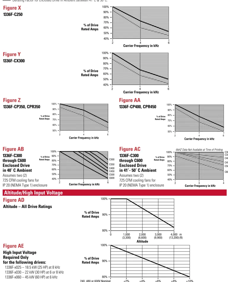
Altitude
1000 m (3300 ft) maximum without derating.
(refer to the Derating Guidelines on
Pages 56-60
).
Ambient Operating Temperature
IP00, Open:
0 to 50 degrees C (32 to 122 degrees F).
IP20, NEMA Type 1:
0 to 40 degrees C (32 to 104 degrees F).
IP54, NEMA Type 12:
0 to 40 degrees C (32 to 104 degrees F).
IP65, NEMA Type 4:
0 to 40 degrees C (32 to 104 degrees F).
(refer to the Derating Guidelines on
Pages 56-60
).
Storage Temperature (all constructions)
- 40 to 70 degrees C (- 40 to 158 degrees F).
Relative Humidity
5 to 95% non-condensing.
Shock
15G peak for 11 ms duration (±1.0 ms).
Vibration
0.006 inches (0.152 mm) displacement, 1G peak.
Agency Certification
U.L. Listed
CSA Certified
Marked for all applicable directives
1Emissions
EN 50081-1
EN 50081-2
EN 55011 Class A
EN 55011 Class B
Immunity
EN 50082-1
EN 50082-2
IEC 801-1, 2, 3, 4, 6, 8 per EN 50082-1, 2
Low Voltage
EN 60204-1
PREN 50178
U
L
C Q E T N O C D N I 6 L 6 5 D E T S ILU
L
Q E T N O C D N I 6 L 6 5 D E T S ILProtection Specifications
Environmental Specifications
Input Data
Voltage Tolerance:
–10% of Minimum, +10% of Maximum.
Frequency Tolerance:
48-62 Hz.
Input Phases:
Three-Phase input provides full rating for all drives.
Single-Phase operation is possible for A & B Frame drives
at a derating of 50%.
(refer to frame designations on
Page 22
and the Derating Guidelines on
Pages 56-60
).
Displacement Power Factor
A1 - A3 Frame:
0.80 Standard, 0.95 with Optional Inductor.
A4 Frame & Up:
0.95 Standard.
Efficiency
97.5% at rated amps, nominal line volts.
Maximum Short Circuit Current Rating
200,000A rms symmetrical, 600 volts (when used with AC line fuses specified on
Page 37
).
Method
Sine coded PWM with programmable carrier frequency. Ratings apply to all drives.
A Frame
2-10 kHz. Drive Rating based on 4 kHz.
B Frame
2-8 kHz. Drive Rating based on 4 kHz.
C & D Frame
2-6 kHz. Drive Rating based on 4 kHz.
E Frame & Up
2-6 kHz. Drive Rating based on 2 kHz.
(refer to frame designations on
Page 22
and the Derating Guidelines on
Pages 56-60
).
Output Voltage Range
0 to rated voltage.
Output Frequency Range
0 to 400 Hz.
Frequency Accuracy
Digital Input:
Within ±0.01% of set output frequency.
Analog Input:
Within ±0.4% of maximum output frequency.
Selectable Motor Control
control with full tuning. Standard V/Hz with full custom capability.
Accel/Decel
Two independently programmable accel and decel times.
Each time may be programmed from 0 to 3600 seconds in 0.1 second increments
1.
Intermittent Overload
Constant Torque:
150% of rated output for 1 minute.
Variable Torque:
115% of rated output for 1 minute.
Current Limit Capability
Proactive Current Limit programmable from 20 to 160% of rated output current.
Independently programmable proportional and integral gain.
Inverse Time Overload Capability
Class 10 protection with speed sensitive response.
Investigated by U.L. to comply with N.E.C. Article 430. U.L. file E59272, volume 4/6.
Local Programming and Display Panel
Backlit Supertwist LCD display. 2 lines, 16 characters each. Multi-lingual display of status, faults
Electrical Specifications
Control Specifications
Requirements: Each 1336 PLUS
II
Drive has constant and variable torque capabilities.
Note: Drive ratings are at nominal values. Refer to Derating Guidelines on
Pages 56-60.
Constant Torque
Variable Torque
Variable Torque
Cat.
Input
Input
Output
Output
Input
Input
Output
Output
Input
Input
Output
Output
No.
kVA
Amps
kVA
Amps
kVA
Amps
kVA
Amps
kVA
Amps
kVA
Amps
200-240V Drives
240V Drives
AQF05 1.1 2.8 0.9 2.3 1.1 2.8 0.9 2.3 AQF07 1.4 3.5 1.2 3.0 1.4 3.5 1.2 3.0 AQF10 2.2 5.4 1.8 4.5 2.2 5.4 1.8 4.5 AQF15 2.9 7.3 2.4 6.0 2.9 7.3 2.4 6.0 AQF20 3.9 9.7 3.2 8.0 3.9 9.7 3.2 8.0 AQF30 5.7 14.3 4.8 12 5.7 14.3 4.8 12 AQF50 8.5 21.3 7.2 18 8.5 21.3 7.2 18 AQF75 9.0 22.6 8.8 22 9.0 22.6 8.8 22 A007 10-12 28 8.8 22 10 23 8.8 22 A010 12-14 35 14 34 14 35 14 34 A015 17-20 49 19 48 20 49 19 48 A020 22-26 63 26 65 26 63 26 65 A025 26-31 75 31 77 31 75 31 77 A030 27-33 79 32 80 33 79 32 80 A040 41-49 119 48 120 49 119 48 120 A050 52-62 149 60 150 62 149 60 150 A060 62-74 178 72 180 74 178 72 180 A075 82-99 238 96 240 99 238 96 240 A100 100-120 289 116 291 120 289 116 291A125
112-134 322
129
325
134
322
129
325
380-480V Drives
480V Drives
400V Drives
BRF05 0.9-1.0 1.3 0.9 1.1 1.1 1.4 1.0 1.2 0.9 1.4 1.0 1.33 BRF07 1.3-1.6 2.0 1.3 1.6 1.7 2.1 1.4 1.7 1.4 2.1 1.4 1.89 BRF10 1.7-2.1 2.6 1.7 2.1 2.2 2.8 1.8 2.3 1.8 2.8 1.8 2.55 BRF15 2.2-2.6 3.3 2.2 2.8 2.8 3.5 2.4 3.0 2.3 3.5 2.4 3.33 BRF20 3.0-3.7 4.6 3.0 3.8 3.8 4.8 3.2 4.0 3.2 4.8 3.2 4.44 BRF30 4.2-5.1 6.4 4.2 5.3 5.7 7.2 4.8 6.0 4.7 7.2 4.8 6.66 BRF50 6.6-8.0 10.0 6.7 8.4 8.5 10.7 7.2 9.0 7.0 10.7 7.2 9.99 BRF75 8.9-11.3 13.6 10.6 13.3 13 15.7 12.3 15.4 10.3 15.7 12.3 19.43 BRF100 10.8-13.6 16.4 12.8 16.1 18.6 22.4 17.5 22 14.7 22.4 17.5 22.00 BRF150 16.1-20.4 24.5 19.1 24 20.4 24.5 19.1 24 16.1 24.5 19.1 24.00 BRF200 18-23 28 22 27 23 28 22 27 18 28 22 27.75 B015 16-21 25 19 24.2 23 28 22 27 18 28 22 29.97 B020 21-26 32 25 31 29 35 27 34 23 35 27 37.74 B025 26-33 40 31 39 36 43 33 42 28 43 33 46.62 B030 30-38 46 36 45 41 49 38 48 32 49 38 53.28 BX040 40-50 61 47 59 50 61 47 59 40 61 47 66.60 B040 38-48 58 48 60 52 63 52 65 41 63 52 72.15 B050 48-60 73 60 75 62 75 61 77 49 75 61 83.25 BX0601 62 75 61 77 62 75 61 77 62 75 61 85.47 B060 54-68 82 68 85 77 93 76 96 61 93 76 106.56 B075 69-87 105 84 106 99 119 96 120 78 119 98 133.20 B100 90-114 137 110 138 124 149 120 150 98 149 120 166.50 B125 113-143 172 138 173 148 178 143 180 117 178 143 199.80 BX150 148 178 143 180 148 178 143 180 148 178 143 199.80 B150 130-164 197 159 199 198 238 191 240 157 238 191 266.40 B200 172-217 261 210 263 241 290 233 292 191 290 233 324.12 B250 212-268 322 259 325 268 322 259 325 212 322 259 360.75 BP/BPR250 212-268 322 259 325 297 357 287 360 235 357 287 399.60 BX250 212-268 322 259 325 297 357 287 360 228 357 279 399.60 B300 235-297 357 287 360 350 421 339 425 261 397 319 471.75 BP/BPR300 235-297 357 287 360 350 421 339 425 277 421 339 471.75 B350 277-350 421 339 425 392 471 378 475 294 446 359 527.25 BP/BPR350 277-350 421 339 425 392 471 378 475 310 471 378 527.25 B400 310-392 471 387 475 433 521 418 525 326 496 398 582.75 BP/BPR400 310-392 471 378 475 438 527 424 532 347 527 424 532.05 B450 343-433 521 418 525 486 585 470 590 372 565 454 654.90 BP/BPR450 347-438 527 424 532 438 527 424 532 347 527 424 532.00 B500 385-486 585 470 590 552 664 534 670 437 664 534 743.70
Constant Torque
Variable Torque
Cat.
Input
Input
Output
Output
Input
Input
Output
Output
No.
kVA
Amps
kVA
Amps
kVA
Amps
kVA
Amps
500-600V Drives
600V Drives
CWF10 2.1-2.5 2.4 2.1 2.0 2.5 2.4 2.1 2.0 CWF20 4.2-5.0 4.8 4.2 4.0 5.0 4.8 4.2 4.0 CWF30 6.2-7.5 7.2 6.2 6.0 7.5 7.2 6.2 6.0 CWF50 8.3-10.0 9.6 8.3 8.0 10.0 9.6 8.3 8.0 CWF75 9-11 10 10 10 11 10 10 10 CWF100 11-13 12 12 12 13 12 12 12 CWF150 17-20 19 19 19 20 19 19 19 CWF200 21-26 25 24 24 26 25 24 24 C025 27-32 31 30 30 32 31 30 30 C030 31-37 36 35 35 37 36 35 35 C040 38-45 44 45 45 45 44 45 45 C050 48-57 55 57 57 57 55 57 57 C060 52-62 60 62 62 62 60 62 62 C075 73-88 84 85 85 88 84 85 85 C100 94-112 108 109 109 112 108 109 109 C125 118-142 137 137 138 142 137 137 138 C150 144-173 167 167 168 173 167 167 168 C200 217-261 251 251 252 261 251 251 252 C250 244-293 282 283 284 293 282 283 284 CX300 256-307 295 297 300 307 295 297 298 C300 258-309 297 299 300 309 297 299 300 C350 301-361 347 349 350 361 347 349 350 CP/CPR350 301-361 347 349 350 361 347 349 350 C400 343-412 397 398 400 412 397 398 400 CP/CPR400 343-412 397 398 400 412 397 398 400 C450 386-464 446 448 450 464 446 448 450 C500 429-515 496 498 500 515 496 498 500 C600 515-618 595 598 600 618 595 598 600Option L4E/L7E1or L4 Contacts must be capable of operating at 10mA current levels without signal degradation. Contact Closure Interface Board Requirements Reed type input devices are recommended.
The L4E/L7E options are compatible with the following Allen-Bradley PLC modules:
•1771-OYL •1771-OZL
Note: Option L4 is the same as Option L4E but without encoder feedback terminals. Option L5E/L8E1or L5 Circuits used with Option L5/L8E must be capable of operating with high = true logic.
+24V AC/DC Interface Board Requirements DC external circuits in the low state must generate a voltage of no more than 8V DC. Leakage current must be less than 1.5 mA into a 2.5k ohm load.
AC external circuits in the low state must generate a voltage of no more than 10V DC. Leakage current must be less than 2.5 mA into a 2.5k ohm load.
Both AC and DC external circuits in the high state must generate a voltage of +20 to +26 volts and source a current of approximately 10 mA for each input.
The L5E/L8E options are compatible with these Allen-Bradley PLC®modules:
• 1771-OB •1771-OQ16 •1771-OB16
•1771-OBD •1771-OYL •1771-OBN
•1771-OZL •1771-OQ •1771-OBB
Analog Option Card Slot A
No Option Card
Two single-ended, non-isolated inputs configurable for a
potentiometer reference, 0-10V, or 0-20 mA signal
LA2
Dual Isolated Input Card
LA6
Isolated Bipolar/Isolated Thermistor Input Card
LA7
Isolated Bipolar Input/Isolated Input Card
Analog Option Card Slot B
No Option Card
One single-ended, non-isolated input configurable for a
potentiometer reference, 0-10V, or 0-20 mA signal and two
single-ended, non-isolated 0-10V only outputs.
LA1
Dual Analog Output Card
LA3
Dual Isolated Output Card
LA4
Isolated Input/Isolated Output Card
LA5
Analog Output/Pulse Output/Pulse Input Card
Digital Input Specifications
Frequency Resolution:
Maximum frequency programmed divided by 32767 (15 bits).
60 Hz – 0.0018 Hz.
100 Hz – 0.003 Hz.
400 Hz – 0.012 Hz.
Contact Outputs
115V AC, 30V DC – 5.0 Amp Resistive – 2.0 Amp Inductive.
(2) Form C Contacts.
(2) Form A Contacts.
All contacts are fully programmable for closure relative to 17 different drive variables
selected through the “CR1-4 Out Select” parameters.
Requirements
Line Driver Encoder 5V DC or 8-15V DC Output.
Minimum Current – 10mA per Channel.
Quadrature or Pulse.
Single Ended or Differential.
Maximum Input Frequency – 250 kHz
Remote I/O
Single drop remote I/O to Allen-Bradley PLCs and SLC 500. Supports full block transfer and
link mode discrete transfer.
RS232/422/485
DFI Protocol – DH485 Protocol – Customer Specific Protocol.
DeviceNet
™DeviceNet to SCANport module – Available for all drive ratings.
Flex
™I/O
Flex I/O to SCANport module – Available for all drive ratings.
SLC
SLC to SCANport module – Available for all drive ratings.
Flexible Analog Inputs and Outputs
Digital Inputs and Outputs
Encoder Inputs
New vector control adds exceptional torque performance to the 1336 PLUS
II
.
This powerful algorithm provides the following performance enhancements.
•
Outstanding low speed torque at speeds as low as 15 rpm, providing a 120:1
constant torque speed range.
•
Improved acceleration control can provide up to 250% breakaway/acceleration torque to move the toughest loads with ease.
•
Solid “out-of-the-box” performance. Enhanced performance can be gained by programming the setup parameters with actual motor
nameplate values. Optimum results can be achieved by programming the actual amps required to generate no load flux and the actual
voltage needed for IR compensation. If these values are not known, setup procedures can determine the exact values.
•
A fast accel mode is provided. Disabling the Adaptive Current Limit feature provides the lowest possible acceleration time for
low inertia applications.
•
A fast flux-up mode is programmable to aid in acceleration with large motors.
•
Selectable Volts/Hertz modes are also available. When selected, they provide full functionality
including Start Boost and Run Boost, Boost Slope and “Full Custom” V/Hz operation.
Simple process control, monitoring a feedback device and adjusting drive output according to feedback requirements can be accomplished
with the 1336 PLUS
II
Proportional and integral gain adjustments plus feedback scaling, error inversion, output clamping and integrator
reset functions allow the Process PI function to control the output of the 1336 PLUS
II
based on the PI reference (setpoint) and the
PI feedback. If the feedback device indicates that the process is moving away from the desired setpoint, the PI software responds by
adjusting the drive output until the feedback again equals the setpoint. Selectable inputs provide “auto/manual” capability for open
loop threading operation. Programmable presets and preloads assure smooth transitions.
PI Reference PI Reference Select pi reference
∑
∑
√
PI Config.sqrt_fdbk PI Config.inv_error PI Config.reset_int PI Feedback Freq Command PI ErrorMaster Frequency Reference
Process KI s Process KP Integral Term = 0 PI + Clamp PI – Clamp PI Output Speed Adder Output Frequency Speed Command Speed Ramp pi feedback PI Feedback Select Compute Speed Accel Control + –1 – + +
∑
+ + PI Output +32767 Parameter 65 –32767 +32767 0 0Sensorless Vector Motor Control
0 100 99 98 97 % of Speed 96 95 10 20 30 40 50 % of Load 60 70 80 90 100 With Slip Compensation Without Slip Compensation
For those applications that require excellent speed regulation,
the 1336 PLUS
II
offers optional encoder feedback. This option
provides closed loop speed regulation from no load to full load
of 0.1%. A feedback encoder and interface board (L4E, L5E or L6E*)
with encoder inputs is required.
*The encoder loss detection feature of the 1336 PLUS II requires the use of L7E, L8E or L9E.
To develop torque in an induction motor, rotor speed “slips” relative
to stator speed. The amount of slip is proportional to the motor
load. While this increased slip provides the necessary torque,
load speed is sacrificed. For those applications where this
speed decrease is unacceptable, the 1336 PLUS
II
offers Slip
Compensation. As load increases, the drive automatically increases
output frequency to provide needed motor slip without a decrease
in speed. The amount of compensation is proportional to the load
increase, allowing one setting for the entire speed range. The
1336 PLUS
II
Slip Compensation function can provide typical
speed regulation of 0.5%.
•
Slip compensation is based on programmed motor flux instead
of drive rated amps, providing more accurate speed regulation.
•
Slip compensation is active for both steady state and
accel/decel conditions.
•
Dynamic response to load changes is parameter adjustable.
•
Slip compensation enhances torque performance at all speeds.
0 Encoder 100 99 98 97 % of Speed 96 95 None 10 20 30 40 50 % of Load 60 70 80 90 100 Slip Comp 0.5% 0.1% 3% Typical
Some applications require that the drive “pick up” a spinning load at its current speed and direction, then accelerate or decelerate to the
actual commanded speed and direction. The 1336 PLUS
II
offers a programmable feature called Flying Start. This feature has the ability
to determine the speed and direction of a rotating motor and begin its output at that speed. The drive will then bring the motor to the
commanded speed. Flying start can be accomplished with or without a motor mounted encoder.
Encoder Feedback
Slip Compensation
Flying Start
The 1336 PLUS
II
can be programmed to perform seven logic steps with or without the use of a programmable controller. These steps can
be based on:
•
Time
•
Digital Input
•
Time and Digital Input
•
Encoder Feedback Counts or Pulse Input Counts
The Step Logic is selected as a continuous loop or fault (End Fault).
Step Logic
The 1336 PLUS
II
has the ability to ride through short power
interruptions. On loss of input power to the drive, the drive offers
two methods of operation.
Diagram 1
With the Line Loss Fault parameter disabled, if a power
interruption occurs (
T1
) the drive will continue to operate off stored
DC bus energy until bus voltage drops to 85% of its nominal value
(
T2
). At this point, the drive output is shut off, allowing the DC bus
to discharge more slowly. The drive will retain its logic and
operating status as long as bus voltage is above the absolute
minimum bus voltage (refer to
Page 7
). If bus voltage should fall
below this level (
T5
), the drive will trip and Undervolt Fault will be
displayed. If input power is restored before this minimum is
reached (
T3
) and bus voltage rises above the 85% level (
T4
), the
drive will restore output power to the motor and resume running.
Diagram 2
With the Line Loss Fault parameter enabled, if input power is lost
(
T1
) the drive will continue to operate until the bus voltage falls
below 85% of nominal (
T2
). At this point the drive output is turned
off and a 500 mS timer is started. One of the following conditions
will then occur:
1. The bus voltage will fall below minimum before the time expires
(
T6
). This will generate an Undervoltage Fault.
2. The bus voltage will remain below 85% but above minimum and
the timer expires (
T5
). This will generate a Line Loss Fault.
3. The input power is restored (
T3
) and the bus voltage rises above
the 85% level before the timer expires (
T4
). This allows the drive
to turn its output on and resume running.
In the event that a line loss condition occurs, the 1336 PLUS
II
provides a variety of programmable selections to control the timing
and method of reconnecting the motor after power returns. Choices include:
•
Use flying start to determine motor speed.
•
Check for motor terminal voltage to determine motor speed.
Output
DIAGRAM 1
T1
T1 = Loss of Power
T2 = Bus Level at 85% of Nominal, Outputs Shut Off T3 = Power Returned
T4 = Outputs Turned On
T5 = Minimum Bus Voltage Level, Undervoltage Fault Point T2 T3T4 T5 Logic Output Off 100% VBUS 85% VBUS Minimum VBUS Undervoltage Fault (depends on [Low Bus Fault])
Output
T1
T1 = Loss of Power
T2 = Bus Level at 85% of Nominal, Outputs Shut Off T3 = Power Returned
T4 = Outputs Turned On
T5 = 500mS Time Out, Line Loss Fault
T6 = Minimum Bus Voltage Level, Undervoltage Fault Point
T2 T4 T6 T5 T3 Logic Output Off 100% VBUS 85% VBUS Minimum VBUS Undervoltage Fault (depends on [Low Bus Fault])
Line Loss Fault
DIAGRAM 2
Power Loss Ride-Thru
The 1336 PLUS
II
offers a fully programmable Volts-per-Hertz mode
that allows maximum performance for applications requiring
multiple motors on a common drive, particularly if the motors are
not of equal size and type (i.e. a 3.7 kW/5 HP and 11 kW/15 HP
motor on a 15 kW/20 HP drive).
Motor
I
2t
protection is separated from the drive power overload
feature. The electronic motor overload operates independently to
provide improved Class 10 protection. Operation at full load amps
will raise the overload to approximately 70-80% of its trip level.
Overloading beyond FLA will move the value towards tripping level
(100%) based on
I
2t
Trip curves are provided for both hot and cold
states. Parameter settings include:
•
Overload Amps from the motor nameplate FLA.
•
Motor OL Fault parameter to disable the fault condition.
•
In addition, Bit 14 (Motor OL Trip) of the Drive Alarm parameter is
high (1) any time the existing level of output current will cause an
Overload Fault to occur.
The overload feature remains speed sensitive with
3 derating choices:
•
Max Derate is used for motors not designed for variable speed.
•
Min Derate is used for motors with a 4:1 speed range (not
intended for operation below 25% of base Speed).
•
No Derate is used for variable speed motors with a speed range
capability of 10:1 or better.
This feature combines stator flux control with an economizer routine to help the end user save energy costs. The Auto Economizer monitors
drive current and compares it against the full load amps (Overload Amps) that the user has programmed into the drive. In load situations
(i.e. idle) where the actual current draw of the motor is significantly less than the programmed overload amps, the drive will automatically
begin reducing the output voltage to the motor. This minimizes flux current in a lightly loaded motor and results in a lower kW usage.
Min Derate 0 80 100 60 40 20 % of Load % of Load % of Load No Derate 0 80 100 60 40 20 % of Base Speed Max Derate 0 80 100 60 40 20 0 25 50 75 100125150175200 Overload Patterns 1 10 1 10 100 1000
Time to Trip vs. Current (Firmware 4.01 & Up)
Multiple of [Overload Amps]
T ime to T rip - Seconds 115% Cold Hot Voltage 0
0 Frequency Motor Rated Maximum
Start Boost
Break Voltage Break Frequency
Maximum Base Voltage
Base Frequency Maximum VoltageMaximum Frequency Motor Rated
Volts-per-Hertz
Motor Overload Protection
Many applications require a “holding brake” function to stop
motor rotation between operations. The 1336 PLUS
II
provides a
programmable DC Hold level and DC Hold time to develop holding
torque in the motor after a ramp-to-stop.
For applications that require a quick stopping time, the 1336 PLUS
II
can “inject” a DC voltage into the motor for a programmed time to
brake the motor to a stop. While this does not take the place of an
external brake for emergency stopping, it is an effective stopping
method under normal operation.
The drive is capable of extended or unlimited injection braking for
both stopping and holding a motor. It provides:
•
Injection braking at selectable levels for extended periods
up to 90 seconds.
•
Extended Hold Braking (up to 90 seconds).
•
Continuous (event ended) Hold Braking. This is accomplished by
setting the Stop mode to “Ramp to Hold”. In this mode, the drive
will decelerate according to the programmed decel ramp. When
the drive reaches zero Hertz output, it will supply programmed
current for hold braking per the DC Hold Level parameter
(limited to 70% of drive rating) until;
a) a Start command is issued,
or
b) the Enable input is opened.
The 1336 PLUS
II
offers the ability to automatically reset a fault (if the condition that causes the fault is no longer present) and restart.
Both the number of reset attempts (0-9) and the time between reset attempts (0-30 Sec.) are programmable. If the condition causing the
fault is still present when the number of “reset/run tries” is exceeded, the drive will shut down and issue a "Max Retries Exceeded" Fault.
This feature will not operate for ground faults or shorted output faults.
The 1336 PLUS
II
displays which of the available adapters currently
“owns” certain control functions. To avoid conflict, some owners
are exclusive (only one device can issue a direction command), while
others can have multiple control (many devices can simultaneously
issue a start command). Owner displays are excellent diagnostic tools,
displaying precisely where drive control commands are coming from.
All external control connections to the 1336 PLUS
II
are made through
a multi-connection communication bus called SCANport. A Frame
drives have 5 available adapter ports while B Frame & larger drives
Volts/Speed Ramp-to-Stop Time Stop Command e g a tl o V d e e p S DC Hold Level DC Hold Time Brake-to-Stop Volts/Speed Voltage
Time Stop Command Speed DC Hold Level DC Hold Time Volts/Speed Ramp-to-Hold Time Stop Command e g a tl o V d e e p S DC Hold Level
Reissuing a Start Command at this point will cause the drive to Restart and Ramp as shown
Opening Enable Input instead of reissuing a Start Command will cause drive to Stop
Adapter 1 currently controlling direction Typical Owner Direction Command
0 1 0 0 0 0 0 0 1 1 1 0 1 1 1
Braking
Reset/Run
Owners
Masks
The 1336 PLUS
II
output frequency can be programmed to modulate
around a set frequency. This is accomplished by programming three
parameters to develop an inertia compensated triangular waveform
– Traverse Period, Max Traverse, and P Jump. In surface driven
winding applications, the waveform developed can be used by
traverse drives to perform the traverse function electronically.
A traverse drive will move the thread back and forth in a diamond
pattern to distribute the thread evenly across a tube surface. To
prevent a build up of thread at the same points on the surface, this
pattern must be altered. This can be accomplished by continuously
varying the speed of the traverse in a cyclical manner over a
specified speed range. With the use of inertia compensation,
the result is a series of distributed diamond patterns over the
entire tube surface.
For applications that require unattended operation, the 1336 PLUS
II
offers the ability to resume running once power is restored after a
power outage. If
"Run On Power Up"
is activated and input power
is lost, when power is restored the drive will
automatically
restart
and run at current command speed if all required signals
are present (Enable, Auxiliary, Not-Stop and Start).
Many control systems issue a 4-20 mA control signal for the drive
to use as a speed reference. The drive will run at minimum speed
with a 4 mA signal and maximum speed with a 20 mA signal. The
drive can also invert this signal to run minimum speed at 20 mA
and maximum speed at 4 mA. Since a minimum signal of 4 mA is
required, the drive must have a “fall back” instruction in the event
of a signal loss (failed transducer or broken wire). The 1336 PLUS
II
contains a “loss select” parameter that offers five choices for
signal failure mode.
1. Stop the drive and issue a fault.
2. Go to minimum speed and issue a warning.
3. Go to maximum speed and issue a warning.
4. Maintain speed and issue a warning.
5. Go to a preset speed and issue a warning.
Time Output
Frequency
Power Lost Power Restored
Output Frequency
Time
Signal Loss –– Warning Issued Drive Ramps to Preset Speed Drive at Command Frequency
Seconds Hertz Maximum Traverse (–) Traverse P-Jump P-Jump (+) P-Jump (–) Output Reference Traverse Period –20 0 10 20 30 40 50 60 20 40 Maximum Traverse (+)
Traverse Function
Run On Power Up
Many mechanical systems have resonant frequencies that can
cause severe vibration. If theses systems are run at these speeds
continuously, this vibration can cause mechanical breakdowns.
The 1336 PLUS
II
offers three programmable Skip Frequencies
that prevent the drive from running continuously at resonant
speeds. An additional parameter allows a programmable Skip
Bandwidth around the skip frequencies
In order to provide complete flexibility in monitoring drive
performance, the 1336 PLUS
II
offers a Process Mode for the
liquid crystal super-twist display on the Human Interface Module.
This feature provides two lines of 16 characters each that can
display any two drive parameters scaled into user selectable units.
Each line uses 8 value display characters and 8 programmable
text characters to create the process display. Simple keystrokes
can designate the process display as the standard display shown
at power up.
The 1336 PLUS
II
contains a fault buffer that records the last four
faults the drive experienced. The buffer stores faults in a first-in
first-out manner. Additional diagnostic parameters are listed in
the Diagnostic Group (Refer to the Parameter List on
Page 18
).
e vi r D y c n e u q e r F l a u t c A Frequency Time Skip Frequency Command Frequency Skip Band 3rd Fault Buffer 1 4th Fault
Next Fault Buffer 0
2nd Fault Buffer 2
1st Fault Buffer 3
Skip Frequencies
Process Display
Frequency Setup (continued)
Pulse In Scale 264 Factor 1/4096 1024 PPR
Encoder PPR 46 Factor 1/4096 1024 PPR
Feature Select
Dwell Frequency 43 0.1 Hertz 0.0/7.0 Hz 0.0 Hz
Dwell Time 44 1 Second 0/10 Sec 0 Sec
Speed Control 77 Settings Selection Parameter Slip Comp Slip @ F.L.A. 42 0.1 Hertz 0.0/10.0 Hz 1.0 Hz
Slip Comp Gain 195 None 1/40 1
Run On Power Up 14 Settings Selection Parameter Disabled
Reset/Run Tries 85 1 Try 0/9 0 Tries
Reset/Run Time 15 0.1 Second 0.5/30.0 Sec 1.0 Sec S Curve Enable 57 Settings Selection Parameter Disabled S Curve Time 56 0.1 Second 0.0/1800.0 Sec 0.0 Sec Language 47 Settings Selection Parameter English Flying Start En 155 Settings Selection Parameter Disabled FStart Forward 156 1 Hz 0/400 Hz 60 Hz FStart Reverse 157 1 Hz 0/400 Hz 0 Hz LLoss Restart 228 Settings Selection Parameter Track Volts LLoss Mode 256 Settings Selection Parameter LoBus>Off LLoss Volts 320 1 Volt 40/80/100 Volts/200/400/500 Volts 59/117/146 Volts Loss Recover 321 1 Volt 20/40/50 Volts/200/400/500 Volts 29/59/73 Volts Ride Thru Volts 322 1 Volt 40/80/100 Volts/200/400/500 Volts 29/59/73 Volts Min Bus Volts 323 1 Volt 100/200/250 Volts/200/400/500 Volts 194/388/485 Volts Traverse Inc 78 0.01 Sec 0.00/30.00 Sec 0.00 Sec Traverse Dec 304 0.01 Sec 0.00/30.00 Sec 0.00 Sec Max Traverse 79 0.01 Hz 0.00/50% [Maximum Freq] 0.00 Hz P Jump 80 0.01 Hz 0.00/25% [Maximum Freq] 0.00 Hz Bus Regulation 288 Settings Selection Parameter Disabled Load Loss Det 290 Settings Selection Parameter Disabled
Load Loss Level 291 1 % 0/100 % 0 %
Load Loss Time 292 1 Second 0/30 Sec 0 Sec Bus Reg Level**/ 325 1 Volt 358/716/895 Volts 358/716/895 Volts Max Bus Volts* 403/807/1009 Volts
Digital I/O
Input Mode 241 Mode # Selection Parameter Status TB3 Term 22 242 Settings Selection Parameter Rev/For Input 3 TB3 Term 23 243 Settings Selection Parameter Jog Input 4 TB3 Term 24 244 Settings Selection Parameter Aux Fault Input 5 TB3 Term 26 245 Settings Selection Parameter Spd Sel 3 Input 6 TB3 Term 27 246 Settings Selection Parameter Spd Sel 2 Input 7 TB3 Term 28 247 Settings Selection Parameter Spd Sel 1 Input 8 Input Status 55 Settings Selection Parameter
CR1 Out Select 158 Settings Selection Parameter At Speed CR2 Out Select 174 Settings Selection Parameter Running CR3 Out Select 175 Settings Selection Parameter Fault CR4 Out Select 176 Settings Selection Parameter Alarm Dig Out Freq 159 0.01 Hz 0.00 Hz/ [Maximum Freq] 0.00 Hz
Dig Out Current 160 0% 0/200% 0%
Dig Out Torque 161 0.1A 0.0/200% of [Rated Amps] 0.0A
Dig At Temp 267 1° C 0/255° C 0
PI Max Error 293 0.01 Hz ±400.00 Hz None Pulse Out Select 280 Settings Selection Parameter Output Freq Pulse Out Scale 281 Factor 1/4096 1024 PPR Pulse In Scale 264 Factor 1/4096 1024 PPR At Time* 327 0.01 Sec 0.00/360.00 0.00 Sec Remote CR Output* 326 Settings None xxxx0000
Analog I/O Anlg In 0 Lo 237 0.1 % ±300.0% 0.0% Anlg In 0 Hi 238 0.1 % ±300.0% 100.0% Anlg In 1 Lo 239 0.1% ±300.0% 0.0% Anlg In 1 Hi 240 0.1% ±300.0% 100.0% Anlg In 2 Lo 248 0.1% ±300.0% 0.0% Anlg In 2 Hi 249 0.1% ±300.0% 100.0%
Analog Trim En 90 Settings Selection Parameter Disabled Anlg Signal Loss 250 Settings Selection Parameter Disabled 4-20mA Loss Sel 150 Settings Selection Parameter Min/Alarm Anlg Out 0 Sel 25 Settings Selection Parameter Frequency Anlg Out 0 Offset 154 Disabled Selection Parameter Disabled Anlg Out 0 Abs 233 Disabled Selection Parameter Enabled
Anlg Out 0 Lo 234 0.1% ±300.0% 0.0%
Anlg Out 0 Hi 235 0.1% ±300.0% 100.0%
Anlg Out 1 Sel 274 Settings Selection Parameter Current Anlg Out 1 Abs 277 Enabled Selection Parameter Enabled Anlg Out 1 Offset 278 Enabled Selection Parameter Disabled
Anlg Out 1 Lo 275 0.1% ±300.0% 0.0%
Anlg Out 1 Hi 276 0.1% ±300.0% 100.0%
Slot A Option 252 Settings Selection Parameter Standard Group/Param. No. Disp. Units Min./Max. Values Default
Metering
Output Current 54 0.1A 0/200% Rtd. Drv. Out. Current None Output Voltage 1 1 Volt 0/200% Rtd. Drv. Out. Volts None Output Power 23 1 kW ±200% Rtd. Drv. Out. Power None DC Bus Voltage 53 1 Volt 0/200% DC Bus Volt Max. None Output Freq 66 0.01 Hertz ±400.00 Hz None Freq Command 65 0.01 Hertz ±400.00 Hz None Anlg In 0 Freq 138 0.01 Hertz 0.00/400.00 Hz None Anlg In 1 Freq 139 0.01 Hertz 0.00/400.00 Hz None Anlg In 2 Freq 140 0.01 Hertz 0.00/400.00 Hz None Encoder Freq 63 0.01 Hertz 0.00/400.00 Hz None Pulse Freq 254 0.01 Hertz 0.00/400.00 Hz None MOP Freq 137 0.01 Hertz 0.00/400.00 Hz None
Heatsink Temp 70 1° C 0/255° C None
Power OL Count 84 1 % 0/200% None
Motor OL Count 202 1 % 0/200% None
Last Fault 4 Fault # None None
Torque Current 162 0.1A ±200% Drive Rating None Flux Current 163 0.1A ±200% Drive Rating None % Output Power 3 1 % ±200% Drv. Rated Out. Power None % Output Curr 2 1 % 0/200% Rated Drv. Out. Curr. None Elapsed Run Time 279 0.1 Hr 0/6553.5 0
Setup
Input Mode 241 Mode # None Status
Freq Select 1 5 Settings Selection Parameter Adapter 1 Accel Time 1 7 0.1 Second 0.0/3600.0 Sec 10.0 Sec Decel Time 1 8 0.1 Second 0.0/3600.0 Sec 10.0 Sec Minimum Freq 16 1 Hertz 0/120 Hz 0 Hz Maximum Freq 19 1 Hertz 25/400 Hz 60 Hz Stop Select 1 10 Settings Selection Parameter Coast Current Limit 36 1% 20/300% (0.0/300.0***) Rated Amps150% Current Lmt Sel 232 Settings Selection Parameter Current Lmt Adaptive I Lim 227 Settings Selection Parameter Enabled Overload Mode 37 Settings Selection Parameter No Derate Overload Amps 38 0.1A 20/115% Drive Rated Amps 115% Drv. Rtd. VT Scaling 203 Settings Selection Parameter Disabled Motor NP RPM 177 1 RPM 60/24000 RPM 1750 RPM Motor NP Hertz 178 1 Hertz 1/400 Hz 60 Hz Motor NP Volts 190 1 Volt 0/2 x Drive Rated Volts Drv. Rated Volts Motor NP Amps 191 1 Amp 0/2 x Drive Rated Amps Drv. Rated Amps
Advanced Setup
Minimum Freq 16 1 Hertz 0/120 Hz 0 Hz Maximum Freq 19 1 Hertz 25/400 Hz 60 Hz PWM Frequency 45 2 kHz 2/8 kHz (A & B Frame) Based on Drv Type
2 kHz 2/6 kHz (C Frame & up) Based on Drv Type Accel Time 2 30 0.1 Second 0.0/3600.0 Sec 10.0 Sec Decel Time 2 31 0.1 Second 0.0/3600.0 Sec 10.0 Sec Sync Time 307 0.0 Second 0.0/6000.0 Sec 0.0 Sec Stop Select 1 10 Display Drive None Coast DC Hold Time 12 1 Second 0/90.0 Sec 0.0 Sec
DC Hold Level 13 1 % 0/150 % 100 %
Hold Level Sel 231 Settings Selection Parameter DC Hold Lvl Bus Limit En 11 Settings Selection Parameter Disabled Motor Type 41 Settings Selection Parameter Induction Stop Select 2 52 Settings Selection Parameter Coast
KP Amps 193 NA 25/400 100
Speed Brake En* 319 Settings Selection Parameter Disabled Frequency Setup
Freq Select 1 5 Settings Selection Parameter Adapter 1 Freq Select 2 6 Settings Selection Parameter Preset 1 Jog Frequency 24 0.1 Hertz 0.0/400.0 Hz 10.0 Hz Preset Freq 1 27 0.1 Hertz 0.0/400.0 Hz 0.0 Hz Preset Freq 2 28 0.1 Hertz 0.0/400.0 Hz 0.0 Hz Preset Freq 3 29 0.1 Hertz 0.0/400.0 Hz 0.0 Hz Preset Freq 4 73 0.1 Hertz 0.0/400.0 Hz 0.0 Hz Preset Freq 5 74 0.1 Hertz 0.0/400.0 Hz 0.0 Hz Preset Freq 6 75 0.1 Hertz 0.0/400.0 Hz 0.0 Hz Preset Freq 7 76 0.1 Hertz 0.0/400.0 Hz 0.0 Hz Skip Freq 1 32 1 Hertz 0/400 Hz 400 Hz Skip Freq 2 33 1 Hertz 0/400 Hz 400 Hz Skip Freq 3 34 1 Hertz 0/400 Hz 400 Hz Skip Freq Band 35 1 Hertz 0/15 Hz 0 Hz
groups for ease of programming. Grouping replaces a sequentially
numerical parameter list with functional parameter groups that
increase operator efficiency and help reduce programming time.
Faults
Fault Buffer 0 86 Fault Code Fault Storage None Fault Buffer 1 87 Fault Code Fault Storage None Fault Buffer 2 88 Fault Code Fault Storage None Fault Buffer 3 89 Fault Code Fault Storage None Clear Fault 51 Settings Selection Parameter Ready Cur Lim Trip En 82 Settings Selection Parameter Disabled Shear Pin Fault 226 Settings Selection Parameter Disabled Motor OL Fault 201 Settings Selection Parameter Enabled Motor Therm Flt 268 Fault Code Fault Storage Enabled Line Loss Fault 40 Settings Selection Parameter Disabled Blwn Fuse Flt 81 Settings Selection Parameter Enabled Low Bus Fault 91 Settings Selection Parameter Enabled
Fault Data 207 Param. # 1/255 None
Flt Motor Mode 143 Settings Read Only None Flt Power Mode 144 Settings Read Only None Fault Frequency 145 0.01 Hertz 0.00/400.00 Hz None Fault Status 1 146 Bit 1/0 Read Only None Fault Status 2 286 Fault Code Fault Storage None Fault Alarms 1 173 Bit 1/0 Read Only None Fault Alarms 2 287 Fault Code Fault Storage None Flt Clear Mode 39 Settings Selection Parameter Enabled Ground Warning 204 Settings Selection Parameter Disabled Phase Loss Mode* 330 Settings Selection Parameter Disabled Phase Loss Level* 331 0.1 Volts 5.1/10.1/12.7Volts/22.5/45.0/56.2 Volts 9.0/18.0/22.5 Volts Precharge Fault* 332 Settings Selection Parameter Enabled
Diagnostics
Drive Status 1 59 Bit 1/0 Read Only None Drive Status 2 236 Bit 1/0 Read Only None Application Sts 316 Bit 1/0 Read Only None Drive Alarm 1 60 Bit 1/0 Read Only None Drive Alarm 2 269 Bit 1/0 Read Only None Latched Alarms 1 205 Bit 1/0 Read Only None Latched Alarms 2 270 Bit 1/0 Read Only None Input Status 55 Bit 1/0 Read Only None Freq Source 62 Settings Read Only Use Last Freq Command 65 0.01 Hertz ±400.00 None Drive Direction 69 Settings Read Only None Stop Mode Used 26 Settings Read Only Coast Motor Mode 141 Settings Read Only None Power Mode 142 Settings Read Only None
Output Pulses 67 1 Pulse 0/65535 None
Current Angle 72 1 Deg. Read Only None
Heatsink Temp 70 1° C. 0/255° C None
Set Defaults 64 Settings Selection Parameter Ready DC Bus Memory 212 1 Volt Read Only None
Meas. Volts 272 1 Volt Read Only None
EEPROM Cksum 172 None Read Only None
Ratings
Rated Volts 147 1 Volt Read Only Drive Rating Rated Amps 170 0.1 A Read Only Drive Rating
Rated kW 171 kW Read Only Drive Rating
Firmware Ver. 71 None Read Only 0.00
Cntrl Board Rev 251 None Read Only 0.00 Rated CT Amps 148 0.1A Read Only Drive Rating Rated CT kW 149 kW Read Only Drive Rating Rated VT Amps 198 0.1A Read Only Drive Rating Rated VT kW 199 kW Read Only Drive Rating
Drive Type 61 Read Only Drive Rating
Masks
Direction Mask 94 Bit 1/0 0/1 01111110
Start Mask 95 Bit 1/0 0/1 01111111
Jog Mask 96 Bit 1/0 0/1 01111111
Reference Mask 97 Bit 1/0 0/1 01111111
Accel Mask 98 Bit 1/0 0/1 01111111
Decel Mask 99 Bit 1/0 0/1 01111111
Fault Mask 100 Bit 1/0 0/1 01111111
MOP Mask 101 Bit 1/0 0/1 01111111
Owners (continued)
MOP Owner 110 Bit 1/0 Read Only None
Traverse Owner 306 Bit 1/0 Read Only None
Sync Owner 309 Bit 1/0 Read Only None
Local Owner 179 Bit 1/0 Read Only None Adapter I/O
Data In (8) 111-118 Parameter # None 0 Data Out (8) 119-126 Parameter # None 0 Alt Type 2 Cmd 315 Settings Selection Parameter Disabled
Process Display
Process 1 Par 127 Parameter # None 1 Process 1 Scale 128 Numeric ±327.67 +1.00 Process 1 Txt 1-8 129-136 ASCII Code None Volts Process 2 Par 180 Parameter # None 54 Process 2 Scale 181 Numeric ±327.67 +1.00 Process 2 Txt 1-8 182-189 ASCII Code None Amps
Encoder Feedback
Speed Control 77 Settings Selection Parameter Slip Comp Encoder Type 152 Settings Selection Parameter Quadrature
Encoder PPR 46 Factor 1/4096 1024 PPR
Maximum Speed 151 1 Hertz 0/400 Hz 400 Hz
Motor Poles 153 1 Pole Read Only None
Speed Kl 165 Numeric 0/20000 100
Speed KP 164 Numeric 0/20000 0
Speed Error 166 0.01 Hz ±8.33% [Base Frequency] None Speed Integral 167 0.01 Hz ±8.33% [Base Frequency] None Speed Adder 168 0.01 Hz ±8.33% [Base Frequency] None Slip Adder 255 0.01 Hz ±8.33% [Base Frequency] None Motor NP RPM 177 1 RPM 60/24000 RPM 1750 RPM Motor NP Hertz 178 1 Hertz 1/400 Hz 60 Hz
Encoder Counts 283 1 Count ±32767 0
Enc Count Scale 282 0/4096 None
Encoder Loss Sel 284 Settings Selection Parameter Disabled Encoder Freq 63 0.01 Hertz 0.00/400.00 Hz None Max Enc Counts* 328 1 Count 0/32767 0
Process PI
Speed Control 77 Settings Selection Parameter Slip Comp
PI Config 213 Bit 1/0 0/1 00000000
PI Status 214 Bit 1/0 Read Only None
PI Ref Select 215 Settings Selection Parameter Preset 1 PI Fdbk Select 216 Settings Selection Parameter Analog In 1 PI Reference 217 0.01 Hertz ±400.00 Hz None PI Feedback 218 0.01 Hertz ±400.00 Hz None PI Error 219 0.01 Hertz ±400.00 Hz None PI Output 220 0.01 Hertz ±400.00 Hz None
KI Process 221 N/A 0/1024 128
KP Process 222 N/A 0/1024 256
PI Neg Limit 223 0.01 Hz ±400.00 Hz –8.33% [Max Freq] PI Pos Limit 224 0.01 Hz ±400.00 Hz +8.33% [Max Freq] PI Preload 225 0.01 Hz ±8.33 [Max Freq] 0.00 Hz
Motor Control
Control Select 9 Settings Selection Parameter Sens Vector Flux Amps Ref 192 0.1A 0.0/75% Drive VT Rtd. Amps 0.0A IR Drop Volts 194 1 Volt 0/25% Drive Rated Voltage 0 Volts Flux Up Time 200 0.1 Sec 0.0/5.0 Sec 0.0 Sec Start Boost 48 1 Volt 0/9.5% Drive Rated Voltage 0 Volts Run Boost 83 1 Volt 0/9.5% Drive Rated Voltage 0 Volts
Boost Slope 169 None 1.0/8.0 1.5
Break Voltage 50 1 Volt 0/50% Drive Rated Voltage 25% Drive Rtd. V Break Frequency 49 1 Hertz 0/120 Hz 25% [Max. Freq] Base Voltage 18 1 Volt 25/120% Drive Rated Voltage Drive Rtd. Volts Base Frequency 17 1 Hertz 25/400 Hz 60 Hz Maximum Voltage 20 1 Volt 25/120% Drive Rated Voltage Drive Rtd. Volts
Run/Accel Volts 317 1% 50%/100% 100%
Sync Loss Sel 310 Settings Selection Parameter Disabled
Sync Loss Gain 311 Numeric 0/100 40
02 Auxiliary Fault The auxiliary input interlock is open
03 Power Loss Fault DC bus voltage remained below 85% of nominal for longer than 500ms 04 Undervolt Fault DC Bus voltage fell below the minimum value
05 Overvolt Fault DC bus voltage exceeded maximum value
06 Motor Stall Fault Current remained over 150% of [Rated Amps] for more than 4 seconds 07 Overload Fault Internal electronic overload trip
08 Overtemp Fault Heatsink temperature exceeds a predefined value of 90° C (195° F) 09 Open Pot Fault An external pot is connected and the common side of the pot is open
10 Serial Fault A SCANport adapter has been disconnected and the [Logic Mask] bit for that adapter is set to “1” 11 Op Error Fault A SCANport device requests a Read or Write of data type not supported
12 Overcurrent Flt Overcurrent is detected in instantaneous overcurrent trip circuit
13 Ground Fault A current path to earth ground in excess of 100A has been detected at one or more of the drive output terminals 14 Option Error An analog option board has been installed in the wrong slot
15 Motor Thermistor An analog option board with thermistor input is installed and the value at the terminals is less than 60 ohms or greater than 3300 ohms 16 Bipolar Dir Flt 3 Wire-Bipolar input is the active frequency reference and direction control is not possible
2 Wire-Run Forward or Run Reverse commands attempt direction control, but bipolar input is not masked from direction control 19 Precharge Fault The precharge device was open 20ms after the end of a line loss condition or the bus charging alarm remains on for 20 seconds 22 DSP Reset Fault Power-up has been attempted with an Open Stop contact or Closed Start contact
23 Loop Overrn Fault An overrun of the 2.5ms control loop has occurred 24 Motor Mode Fault A fault has been detected originating from the Control Board 26 Power Mode Fault The internal power mode variable received an incorrect value 29 Hertz Err Fault This fault indicates that there is not a valid operating frequency
30 Hertz Sel Fault A frequency select parameter has been programmed with an out-of-range value 32 EEPROM Fault EEPROM is being programmed and will not write a new value
33 Max Retries Fault Drive unsuccessfully attempted to reset a fault and resume running for the programmed number of tries 34 Prm Access Flt A communication error occurred between the microprocessor and serial EEPROM or DSP
35 Neg Slope Fault Drive software detected a portion of the v/hz curve with a negative slope 36 Diag C Lim Flt The [Cur Lim Trip En] parameter was enabled
38 Phase U Fault A phase-to-ground fault has been detected between the drive and motor in this phase 39 Phase V Fault A phase-to-ground fault has been detected between the drive and motor in this phase 40 Phase W Fault A phase-to-ground fault has been detected between the drive and motor in this phase 41 UV Short Fault Excessive current has been detected between these two output terminals
42 UW Short Fault Excessive current has been detected between these two output terminals 43 VW Short Fault Excessive current has been detected between these two output terminals
47 Xsistr Desat Flt Output transistor(s) operating in the active region instead of desaturation. (Frame C & Above) 48 Reprogram Fault The drive was commanded to write default values to EEPROM
49 Input Phase Flt The drive is operated on single phase power
50 Poles Calc Fault Generated if the calculated value of [Motor Poles] is less than 2 or greater than 32 51 Bgnd 10ms Over Microprocessor loop fault
52 Fgnd 10ms Over Microprocessor loop fault
53 EE Init Read Trouble reading EEPROM during initialization or gate drive board needs replacing 54 EE Init Value Stored parameter value out of range on initialization
55 Temp Sense Open Heatsink thermistor is open or malfunctioning
56 Precharge Open The precharge circuit was commanded to close, but was detected to be open
57 Ground Warning A current path to earth ground in excess of 2A has been detected at one or more of the drive output terminals 58 Blwn Fuse Flt The bus fuse in 30kW (40 HP) and up drives has blown
61 Mult Prog Input A single source input function has been programmed to more than one input or more than one “Run Reverse” input 62 Ill Prog Input [Fault Data] = 98: “3 Wire” is selected as the [Input Mode] and one or more digital inputs are programmed to “Run Reverse” 63 Shear Pin Fault Programmed [Current Limit] amps has been exceeded
64 Power Overload The drive rating of 150% for 1 minute has been exceeded
65 Adptr Freq Err The SCANport adapter sent an illegal frequency reference to the drive
66 EEPROM Checksum The checksum read from the EEPROM does not match the checksum calculated from the EEPROM data 68 ROM or RAM Fit Internal power-up ROM or RAM tests have not executed properly
69 Step Logic Flt [SLx Step Jump] is set to “End Fault” or [Encoder Counts] has reached the endpoint of ±32767
Over 40 faults can be displayed through the Human Interface Module. The display indicates a fault by showing a brief text statement
relating to the fault that will be displayed until a drive reset is initiated.
Fault
1336 PLUS
II
Pre-Installation
ATTENTION:
The following information is merely a guide for proper installation. The Allen-Bradley Company cannot assume
responsibility for the compliance or the noncompliance to any code, national, local or otherwise for the proper
installation of this drive or associated equipment.
Features
All Dimensions in Millimeters and (Inches) All Weights in Kilograms and (Pounds)
C Max. D A Y CC E B Z BB AA A 215.9 (8.50) 215.9 (8.50) 215.9 (8.50) 260.0 B 290.0 (11.42) 290.0 (11.42) 290.0 (11.42) 350.0 C Max. 160.0 (6.30) 180.5 (7.10) 207.0 (8.15) 212.0 D 185.2 (7.29) 185.2 (7.29) 185.2 (7.29) 230.0 E 275.0 (10.83) 275.0 (10.83) 275.0 (10.83) 320.0 Y 15.35 (0.60) 15.35 (0.60) 15.35 (0.60) 15.35 Z 7.5 (0.30) 7.5 (0.30) 7.5 (0.30) 15.35 AA 130.0 (5.12) 130.0 (5.12) 130.0 (5.12) 130.0 BB 76.2 (3.00) 76.2 (3.00) 76.2 (3.00) 133.0 CC 85.3 (3.36) 85.3 (3.36) 85.3 (3.36) 86.0 Shipping Weights 4.31 (9.5) 5.49 (12.1) 6.71 (14.8) 15.90
Mounting Holes (4) – See Detail
7.0 (0.28)
7.0 (0.28) 12.7 (0.50)
12.7 (0.50)
Mounting Hole Detail
Three-Phase Rating 1, 2 200-240V 0.37-0.75 kW 0.5-1 HP 1.2-1.5 kW 1.5-2 HP 2.2-3.7 kW 3-5 HP – 5.5-11 kW 7.5-15 HP 15-22 kW 20-30 HP 30-45 kW 40-60 HP 56-93 kW 75-125 HP – – 380-480V 0.37-1.2 kW 0.5-1.5 HP 1.5-2.2 kW 2-3 HP 3.7 kW 5 HP 5.5-15 kW * 7.5-20 HP 11-22 kW * 15-30 HP 30-45 kW 40-60 HP 45-112 kW 60-150 HP 112-187 kW 150-250 HP 187-336 kW 250-450 HP 187-448 kW 250-600 HP 500-600V – – – 0.75-15 kW 1-20 HP – – 18.5-45 kW 25-60 HP 56-93 kW 75-125 HP 112-187 kW 150-300 HP 261-298 kW 350-400 HP 224-448 kW 300-600 HP Frame Reference A1 A2 A3 A4 B1/B2 C D E F G Frame Reference A1 A2 A3 A4
Bottom View Will Vary with HP – See Bottom View Dimensions
Use care when choosing Frame Reference - Some ratings may exist in another frame size.
*
IP 20 (NEMA Type 1) Dimensions – Frames A1 Through A4
IP 20 (NEMA Type 1) Dimensions – Frames B, C, D
Bottom View Will Vary with HP See Bottom View Dimensions
F G
C Max.
All Dimensions in Millimeters and (Inches) All Weights in Kilograms and (Pounds)
D A Y CC E B Z BB AA 7.1 (0.28) 7.1 (0.28) 12.7 (0.50) 12.7 (0.50) 10.4 (0.41) Dia. 19.0 (0.75) Dia. 14.7 (0.58)
Mounting Hole Detail (Frames B & C)
Mounting Hole Detail (Frame D)
Mounting Holes (4) – See Detail
Frame D Frames B & C
IP 20 (NEMA Type 1) & Open Dimensions – Frame E
C Max.
All Dimensions in Millimeters and (Inches) All Weights in Kilograms and (Pounds)
D A Y CC E B Z BB AA
Mounting Holes (4) – See Detail
Shipping Weight 186 (410) 163 (360) CC 151.9 (5.98) 126.3 (4.97) Frame Reference E – Enclosed E – Open A 511.0 (20.12) 511.0 (20.12) B 1498.6 (59.00) 1498.6 (59.00) C Max. 424.4 (16.71) 372.6 (14.67) D 477.5 (18.80) 477.5 (18.80) E 1447.8 (57.00) 1447.8 (57.00) Y 16.8 (0.66) 16.8 (0.66) Z 40.1 (1.61) 40.1 (1.61) AA 195.0 (7.68) 138.4 (5.45) BB 901.4 (35.49) 680.0 (26.77) 37.9 (1.49)
Mounting Hole Detail
See Bottom View Dimensions for Details
10.4 (0.41) Dia. 133.4
(5.25)
17.0 (0.67)
IP 20 (NEMA Type 1) & Open Dimensions – Frame F
2286.0 (90.00) 762.0 (30.00) 252.7 (9.95) 635.0 (25.00) Open Chassis 487.7 (19.20) 37.9 (1.49) 274.8 (10.82) 193.0 (7.60) 1219.2 (48.00) 527.1 (20.75) 31.5 698.5Removable Lifting Angle
63.5 (2.50)
196.9 (7.75)
108.0 (4.25) x 158.8 (6.25) Removable Plate for 19.1 (0.75) Fan Vertical CL 711.2 (28.00) Fan Horiz. CL 82.6 (3.25) 501.7 (19.75) 158.8 (6.25)
Open Dimensions – Frame F “Roll-In” Chassis
DANGER DANGER DANGER DANGER DANGER DANGER T-L3 R-L1 S-L2 W-M3 TE U-M1 PE V-M2 717.6 (28.25) 463.6 (18.25) 635.0 (25.00) 1543.3 (60.76)IP 20 (NEMA Type 1) & Open Dimensions – Frame G
2324.1 (91.50) Removable Lifting Angle
762.0 (30.00) Open Chassis Dimensions
635.0 (25.00) 63.5 (2.50) Conduit Access Area 648.0 (25.51) 19.3 (0.76) 1524.0 (60.00) 117.3 (4.62) Depth = 508.3 (20.01) Weight = 453.6 kg (1000 lbs.)
All Dimensions in Millimeters and (Inches) Important: Two (2) 725 CFM fans are
required if an open type drive is mounted in a user supplied enclosure.
IP 65/54 (NEMA Type 4/12) Dimensions
Typical Top and Bottom
Detail A See Detail A See Detail B A D F G H C E B 12.7 (0.50) 12.4 (0.49) 7.9 (0.31) Frame Reference A1 A2 A3 A4 B1 B2 A 430.0 (16.93) 430.0 (16.93) 430.0 (16.93) 655.0 (25.79) 655.0 (25.79) 655.0 (25.79) B 525.0 (20.67) 525.0 (20.67) 525.0 (20.67) 650.0 (25.59) 650.0 (25.59) 900.0 (35.43) C 350.0 (13.78) 350.0 (13.78) 350.0 (13.78) 425.0 (16.74) 425.0 (16.74) 425.0 (16.74) E 500.1 (19.69) 500.1 (19.69) 500.1 (19.69) 625.1 (24.61) 625.1 (24.61) 875.0 (34.45) D 404.9 (15.94) 404.9 (15.94) 404.9 (15.94) 629.9 (24.80) 629.9 (24.80) 629.9 (24.80) F 250.0 (9.84) 250.0 (9.84) 250.0 (9.84) 293.0 (11.54) 293.0 (11.54) 293.0 (11.54) G N/A N/A N/A 63.5 (2.50) 63.5 (2.50) 63.5 (2.50) H N/A N/A N/A 76.2 (3.00) 76.2 (3.00) 76.2 (3.00) All Dimensions in Millimeters and (Inches)
All Weights in Kilograms and (Pounds)
7.1 (0.28) Dia. 12.7 (0.50) 12.7 (0.50) Dia. 14.3 (0.56) Dia. Drive Heatsink Detail B 19.1 (0.75) 19.1 (0.75) Dia. 5.5 kW (7.5 HP) at 200-240V AC 11 kW (15 HP) at 380-480V AC 7.5-11 kW (10-15 HP) at 200-240V AC 15-22 kW (20-30 HP) at 380-480V AC Approx. Ship Weight 16.8 (37.0) 17.9 (39.4) 18.6 (41.0) 39.5 (87.0) 44.7 (98.5) 56.5 (124.5)
IP 20 (NEMA Type 1) Bottom View Dimensions – Frames A-C
All Dimensions in Millimeters and (Inches)
Frames B and C
Frames A1 through A4
L M Frame Reference A1 A2 A3 A4 L 111.8 (4.40) 132.3 (5.21) 158.8 (6.25) 164.0 (6.45) M 105.4 (4.15) 126.0 (4.96) 152.4 (6.00) 164.0 (6.45) N 86.3 (3.40) 106.9 (4.21) 133.4 (5.25) 139.0 (5.47) P 31.0 (1.22) 31.0 (1.22) 31.0 (1.22) 27.0 (1.06) Q 69.1 (2.72) 69.1 (2.72) 69.1 (2.72) 65.0 (2.56) R 102.1 (4.02) 102.1 (4.02) 102.1 (4.02) 97.0 (3.82) S 135.4 (5.33) 135.4 (5.33) 135.4 (5.33) 128.7 (5.07) Q R P S 28.6/34.9 (1.13/1.38) Conduit Knockout - 3 Plcs. 22.2 (0.88) Conduit Knockout - 1 Plc. M N L Q R P S 22.2/28.6 (0.88/1.13) Conduit Knockout - 3 Plcs. 22.2 (0.88) Conduit Knockout - 1 Plc.Fans will be present on A4 Frame Fans are present on these drives
Input Catalog kW/HP
Voltage Frame Number Rating
230 A4 F75 5.5 (7.5) 460 A4 F75 5.5 (7.5) F100 7.5 (10) F150 11 (15) F200 15 (20) 575 A4 F30 2.2 (3) F50 3.7 (5) F75 5.5 (7.5) F100 7.5 (10) F150 11 (15) F200 15 (20)
IP 20 (NEMA Type 1) Bottom View Dimensions – Frames D-G
305.3 (12.02) 178.3 (7.02) 50.8 (2.0) 38.6 (1.52) 432.3 (17.02) 88.9/101.6 (3.50/4.00) Conduit Knockout - 3 Plcs. 12.7 (0.50) Conduit Knockout - 6 Plcs.All Dimensions in Millimeters and (Inches)
209.6 (8.25)
Frame E
Frame G
Frame D
343.9 (13.54) 261.4 (10.29) 131.6 (5.18) 198.1 (7.80) 52.1 (2.05) 144.0 (5.67) 169.4 (6.67) 204.5 (8.05) 153.7 (6.05) 311.2 (12.25) 260.4 (10.25) 34.9 (1.38) Conduit Knockout - 3 Plcs. 34.9/50.0 (1.38/1.97) Conduit Knockout - 1 Plc. 62.7/76.2 (2.47/3.00) Conduit Knockout - 2 Plcs. (Bottom) (Top) 29.0 (1.14) 15.9 (0.63) Dia. - 2 Mtg. Holes 431.8 (17.00) 381.0 (15.00) 298.5 (11.75) 42.9 (1.69) 254.0 (10.00) 547.6 (21.56) Conduit Access Area Conduit Access Area660.4 (26.00) 50.8 (2.00)
431.8 (17.00)