Chapter 1
Rotation of an Object About a Fixed
Axis
1.1
The Important Stuff
1.1.1
Rigid Bodies; Rotation
So far in our study of physics we have (with few exceptions) dealt with particles, objects whose spatial dimensions were unimportant for the questions we were asking. We now deal with the (elementary!) aspects of the motion of extended objects, objects whose dimensions are important.
The objects that we deal with are those which maintain a rigid shape (the mass points maintain their relative positions) but which can change their orientation in space. They can havetranslational motion, in which their center of mass moves but also rotational motion, in which we can observe the changes in direction of a set of axes that is “glued to” the object. Such an object is known as a rigid body. We need only a small set of angles to describe the rotation of a rigid body. Still, the general motion of such an object can be quite complicated.
Since this is such a complicated subject, we specialize further to the case where a line of points of the object is fixed and the object spins about a rotation axis fixed in space. When this happens, every individual point of the object will have a circular path, although the radius of that circle will depend on which mass point we are talking about. And the orientation of the object is completely specified by one variable, an angle θ which we can take to be the angle between some reference line “painted” on the object and the x axis (measured counter-clockwise, as usual).
Because of the nice mathematical properties of expressing the measure of an angle in radians, we will usually express angles in radians all through our study of rotations; on occasion, though, we may have to convert to or from degrees or revolutions. Revolutions, degrees and radians are related by:
1 revolution = 360 degrees = 2πradians 1
q
r
s
Figure 1.1: A point on the rotating object is located a distancerfrom the axis; as the object rotates through an angle θ it moves a distance s.
[Later, because of its importance, we will deal with the motion of a (round) object which rolls along a surface without slipping. This motion involves rotation and translation, but it is not much more complicated than rotation about a fixed axis.]
1.1.2
Angular Displacement
As a rotating object moves through an angle θ from the starting position, a mass point on the object at radiusrwill move a distances;s length of arc of a circle of radiusr, subtended by the angleθ.
When θ is in radians, these are related by
θ = s
r θ in radians (1.1)
If we think about the consistency of the units in this equation, we see that since s and
r both have units of length, θ is really dimensionless; but since we are assuming radian measure, we will often write “rad” next to our angles to keep this in mind.
1.1.3
Angular Velocity
The angular position of a rotating changes with time; as with linear motion, we study the rate of change of θ with time t. If in a time period ∆t the object has rotated through an angular displacement ∆θ then we define theaverage angular velocityfor that period as
ω = ∆θ
∆t (1.2)
A more interesting quantity is found as we let the time period ∆t be vanishingly small. This gives us the instantaneous angular velocity,ω:
ω = lim ∆t→0 ∆θ ∆t = dθ dt (1.3)
Angular velocity has units of rad
s , or equivalently, 1 s or s−
1.1. THE IMPORTANT STUFF 3 In more advanced studies of rotational motion, the angular velocity of a rotating object is defined in such a way that it is avector quantity. For an object rotating counterclockwise about a fixed axis, this vector has magnitudeωand points outward along the axis of rotation. For our purposes, though, we will treat ω as a number which can be positive or negative, depending on the direction of rotation.
1.1.4
Angular Acceleration; Constant Angular Acceleration
The rate at which the angular velocity changes is the angular acceleration of the object. If the object’s (instantaneous) angular velocity changes by ∆ω within a time period ∆t, then the average angular accelerationfor this period is
α= ∆ω
∆t (1.4)
But as you might expect, much more interesting is the instantaneous angular accelera-tion, defined as α= lim ∆t→0 ∆ω ∆t = dω dt (1.5)
We can derive simple equations for rotational motion if we know that α is constant. (Later we will see that this happens if the “torque” on the object is constant.) Then, if θ0
is the initial angular displacement, ω0 is the initial angular velocity and α is the constant
angular acceleration, then we find:
ω = ω0+αt (1.6)
θ = θ0+ω0t+ 12αt2 (1.7)
ω2 = ω02+ 2α(θ−θ0) (1.8)
θ = θ0+ 12(ω0+ω)t (1.9)
whereθ andωare the angular displacements and velocity at timet. θ0 and ω0 are the values
of the angle and angular velocity at t= 0.
These equations have exactly the same form as the equations for one–dimensional linear motion given in Chapter 2 of Vol. 1. The correspondences of the variables are:
x↔θ v ↔ω a↔α .
It is almost always simplest to set θ0 = 0 in these equations, so you will often see
Eqs. 1.6—1.9 written with this substitution already made.
1.1.5
Relationship Between Angular and Linear Quantities
As we wrote in Eq. 1.1, when a rotating object has an angular displacement ∆θ, then a point on the object at a radius r travels a distance s=rθ. This is a relation between the angular motion of the point and the “linear” motion of the point (though here “linear” is a bit of a misnomer because the point has a circular path). The distance of the point from the axis
does not change, so taking the time derivative of this relation give the instantaneous speed of the particle as:
v = ds
dt =r dθ
dt =rω (1.10)
which we similarly call the point’slinear speed(or, tangential speed),vT) to distinguish
it from the angular speed. Note, all points on the rotating object have the same angular speed but their linear speeds depend on their distances from the axis.
Similarly, the time derivative of the Eq. 1.10 gives the linear acceleration of the point:
aT =
dv dt =r
dω
dt =rα (1.11)
Here it isessential to distinguish thetangential acceleration from thecentripetal acceleration that we recall from our study of uniform circular motion. It isstill true that a point on the wheel at radius r will have a centripetal acceleration given by:
ac = v2 r = (rω)2 r =rω 2 (1.12)
These two components specify the acceleration vector of a point on a rotating object. (Of course, if α is zero, then aT = 0 and there is only a centripetal component.)
1.1.6
Rotational Kinetic Energy
Because a rotating object is made of many mass points in motion, it has kinetic energy; but since each mass point has adifferent speedv our formula fromtranslational particle motion,
K = 1 2mv
2no longer applies. If we label the mass points of the rotating object as m
i, having
individual (different!) linear speeds vi, then the total kinetic energy of the rotating object is
Krot = X i 1 2miv 2 i = 12 X I miv2i
If ri is the distance of the ith mass point form the axis, thenvi =riω and we then have:
Krot = 12 X i mi(riω)2 = 12 X i (mir2i)ω2 = 12 X i miri2 ! ω2 . The sum P
imir2i is called themoment of inertiafor the rotating object (which we discuss
further in the next section), and usually denotedI. (It is also called therotational inertia
in some books.) It has units of kg·m2 in the SI system. With this simplification, our last
equation becomes
1.1. THE IMPORTANT STUFF 5
1.1.7
The Moment of Inertia; The Parallel Axis Theorem
For a rotating object composed of many mass points, the moment of inertiaI is given by
I =X
i
mir2i (1.14)
I has units of kg·m2 in the SI system, and as we use it in elementary physics, it is a scalar 1 (i.e. a single number which in fact is always positive). More frequently we deal with a
rotating object which is a continuous distribution of mass, and for this case we have the more general expression
I =
Z
r2dm (1.15)
Here, the integral is performed over the volume of the object and at each point we evaluate
r2, where r is the distance measured perpendicularly from the rotation axis.
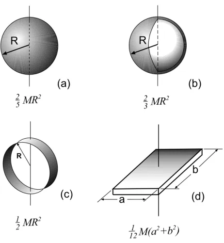
The evaluation of this integral for various of cases of interest is a common exercise in multi-variable calculus. In most of our problems we will only be using a few basic geometrical shapes, and the moments of inertia for these are given in Figure 1.2 and in Figure 1.3.
Suppose the moment of inertia for an object of mass M with the rotation axis passing through the center of mass is ICM. Now suppose we displace the axis parallel to itself by a
distance D. This situation is shown in Fig. 1.4. The moment of inertia of the object about the new axis will have a new value I, given by
I =ICM+MD2 (1.16)
Eq. 1.16 is known as the Parallel Axis Theorem and is sometimes handy for computing moments of inertia if we already have a listing for a moment of inertia through the object’s center of mass.
1.1.8
Torque
We can impart an acceleration to a rotating object by exerting a force on it at a particular point. But it turns out that the force is not the simplest quantity to use in studying rotations; rather it is the torque imparted by the force.
Suppose the force F (whose direction lies in the plane of rotation) is applied at a point
r (relative to the rotation axis which is at the origin O). Suppose that the (smallest) angle betweenrandFisφ. Then the magnitude of the torqueexerted on the object by this force is
|τ|=rF sinφ (1.17)
By some very simple regrouping, this equation can be written as
τ =r(F sinφ) =rFt
R R1 R2 R R L
L
L
(a) (b) (c) (d) (e) (f)MR
2 12M(R
1+
R
2)
2 2ML
2MR
2 1 4ML
2 1 12+
1 12 1ML
2 3MR
2 1 2Figure 1.2: Formulae for the moment of inertiaIfor simple shapes about the axes, as shown. In each case, the mass of the object isM. (a) Hoop about symmetry axis. (b) Annular cylinder about symmetry axis. (c) Solid cylinder (disk) about symmetry axis. (d) Solid cylinder (disk) about axis through CM, perpendicular to symmetry axis. (e) Thin rod about axis through CM, perpendicular to length. (f) Thin rod about axis through one end, perpendicular to length.
1.1. THE IMPORTANT STUFF 7
R
R
(a)
(b)
R(c)
a
(d)
b
MR
2 2 5MR
2 2 3MR
2 1 2M(a
2+b
2)
1 12Figure 1.3: More formulae for moment of inertia I for simple shapes about the axes, as shown. (a) Solid sphere; axis is through a diameter. (b) Spherical shell; axis is through a diameter. (c) Hoop; axis is through a diameter. (d) Rectangular slab; axis is perpendicular, through the center.
CM CM
D
M
(a) (b)
Figure 1.4: (a) Moment of inertia about an axis through the center of mass of an object isICM. (b) We
displace the axis so that it is parallel and a distanceDaway. New moment of inertia is given by the Parallel Axis Theorem. This object looks like some kind of potato, but the theorem will work for any vegetable.
O P r F O P r F O P r F Ft r (a) (b) (c) f f f
Figure 1.5: (a) Rigid body rotates about pointO. A force Fis exerted at point P. (b) Torqueτ can be viewed as the product of the distancerand the tangential component of the force,Ft. (c) Torqueτ canalso be viewed as the product of the forceF and the distancer⊥ (often called the moment arm, or lever arm).
where Ft=F sinφ is the component of the force perpendicular to r, or as
τ = (rsinφ)F =r⊥F
wherer⊥=rsinφis the distance between the axis and the line which we get by “extending”
the force vector into a line often called the line of action. The distance r⊥ is called the
moment arm of the force F. These different ways of thinking about the terms in Eq. 1.17 are illustrated in Fig. 1.5.
Formula 1.17 gives us the magnitude of the torque; strictly speaking, torque is a vector and in more advanced studies of rotations, it must be treated as such. The (vector) torque due a force F is defined as
τττ =r×F
so we see that Eq. 1.17 gives the magnitude of thisvector. For now we will treat torque as anumber which is positive if the force gives a counterclockwise rotation and negative if the force gives a clockwise rotation. What we are callingτ here is really the component of the torque vector along the rotation axis.
To repeat, τ is positive or negative depending on whether the rotation which the force (acting alone) induces is counter-clockwise or clockwise. (However — on occasion we may want to choose the other convention.)
When a number of individual forces act on a rotating object, we can compute the net torque:
τnet=
X
τi
1.1.9
Torque and Angular Acceleration (Newton’s Second Law for
Rotations)
The angular acceleration of a rotating object is proportional to the net torque on the object; they are related by:
1.1. THE IMPORTANT STUFF 9
Linear Quantity Angular Quantity
x θ v ω a α m I F τ p L
Table 1.1: Correspondences between linear and angular quantities where I is the moment of inertia of the object.
This equation looks a lot like Newton’s Second Law for one–dimensional motion, Fx =
max.
1.1.10
Work, Energy and Power in Rotational Motion
As with the (abbreviated) formula for the work done by a force for a small displacement, linear motion, W = Fxdx, we have a formula for the work done by a torque for a small
angular displacementdθ:
W =τ dθ
For a finite angular displacement from θi toθf, the work done is
W =
Z θf
θi
τ dθ
1.1.11
The New Equations Look Like the Old Equations
Although the rotational motion we have begun to study in this chapter is really quite a different thing from the linear motion we have studied up to now, it is of great help in using (or at least remembering) the equations by drawing correspondences between the new rotational quantities and the old linear quantities. These are summarized in Table 1.1. For completeness, we include the quantityangular momentum,L, which will be discussed in the next chapter.
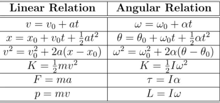
The basic relations between the old linear quantities and the corresponding relations between the new angular quantities are summarized in Table 1.2. Of course, the first three pairs of equations deal with the special case of constant linear or angular acceleration.
A few pointers for solving problems which involve rotations:
•The objects which rotate are (obviously) all extended objects, that is, they have dimensions (width, height. . . ) which can’t be ignored. In some problems the center of mass of the rigid body does move and we may need to understand how the gravitational potential energy of the object changes. The basic answer is that we compute the gravitational potential energy by treating all the mass of the object as being located at its center of mass.
Linear Relation Angular Relation v =v0+at ω=ω0+αt x=x0+v0t+12at2 θ =θ0+ω0t+12αt2 v2 =v2 0 + 2a(x−x0) ω2 =ω02+ 2α(θ−θ0) K = 1 2mv 2 K = 1 2Iω 2 F =ma τ =Iα p=mv L=Iω
Table 1.2: Correspondences between basic equations for linear and angular motion. • Some problems involve a pulley which turns because a string is tightly wrapped around it or because a string passes over the pulley and does not slip against it. In those cases the string exerts a force on the pulley which is tangential, and we use this fact in computing the torque on the pulley. But see the next point. . .
• When a string does pass over a real pulley (i.e. it has mass even though we might still ignore friction in the bearings) and exerts forces on the pulley, the string tension willnot be the same on both sides of the place where it is in contact. This differs from the problems in the chapter on forces where pulleys were involved; there, we used the idealization of massless pulleys, and the tension was the same on both sides.
1.2
Worked Examples
1.2.1
Angular Displacement
1. (a) What angle in radians is subtended by an arc that has length1.80 m and is part of a circle of radius 1.20 m? (b) Express the same angle in degrees. (c) The angle between two radii of a circle is 0.620 rad. What arc length is subtended if the radius is 2.40 m? [HRW5 11-1]
(a)Eq. 1.1 relates arclength, radius and subtended angle. We find:
θ = s
r =
1.80 m
1.20 m = 1.50 rad The subtended angle is 1.50 radians.
(b)To express this angle in degrees use the relation: 360 deg = 2πrad (or, 180 deg =πrad). Then we have:
1.50 rad = (1.50 rad) 180 deg
πrad
!
= 85.9◦
(c) We can find the arc length subtended by an angle θ by the relation: s =θr. Then for an angle of 0.620 rad and radius 2.40 m, the arclength is
1.2. WORKED EXAMPLES 11
1.2.2
Angular Velocity
2. What is the angular speed in radians per second of (a) the Earth in its orbit about the Sun and (b) the Moon in its orbit about the Earth? [Ser4 10-3]
(a)The Earth goes around in a (nearly!) circular path with a period of one year. In seconds, this is: 1 yr = (1 yr) 365.25 day 1 yr ! 24 hr 1 day ! 3600 s 1 hr = 3.156×10⁷s
In one year its angular displacement is 2π radians (all the way around) so its angular speed is ω = ∆θ ∆t = 2π (3.156×10⁷s) = 1.99×10 −7 rad s
(b) How long does it take the moon to go around the earth? That’s a number we need to look up. You ought to know that it is about a month, but any good reference source will tell you that it is 27.3 days, officially called the sidereal period of the moon.. (Things get confusing because of the motion of the earth; full moons occur every 29.5 days, a period which is called the synodic period.) Converting to seconds, we have:
P = 27.3 days = (27.3 days) 24 hr 1 day ! 3600 s 1 hr = 2.36×10⁶s
In that length of time the angular displacement of the moon is 2π so its angular speed is
ω= ∆θ ∆t = 2π (2.36×10⁶s) = 2.66×10 −6 rad s
1.2.3
Angular Acceleration; Constant Angular Acceleration
3. The angular position of a point on the rim of a rotating wheel is given by
θ = 4.0t−3.0t2+t3, where θ is in radians if t is given in seconds. (a) What are
the angular velocities at t = 2.0 s and t = 4.0 s? (b) What is the average angular acceleration for the time interval that begins at t = 2.0 s and ends at t = 4.0 s? (c) What are the instantaneous angular accelerations at the beginning and end of this time interval? [HRW5 11-5]
(a) In the problem we are given the angular position θ as a function of time. To find the (instantaneous) angular velocity at any time, use Eq. 1.3 and find:
ω(t) = dθ dt = d dt 4.0t−3.0t2+t3 = 4.0−6.0t+ 3.0t2
where, if t is given in seconds, ω is given in rad s .
The angular velocities at the given times are then
ω(2.0 s) = 4.0−6.0(2.0) + 3.0(2.0)2 = 4.0rad s
ω(4.0 s) = 4.0−6.0(4.0) + 3.0(4.0)2 = 28.0rad s
(b) Since we have the values of ω and t = 2.0 s and t = 4.0 s, Eq. 1.4 gives the average angular acceleration for the interval:
α = ∆ω ∆t =
(28.0rads −4.0rads ) (4.0 s−2.0 s) = 12.0rads2
The average angular acceleration is 12.0rad s2 .
(c) We find the instantaneous angular acceleration from Eq. 1.5:
α(t) = dω dt = d dt 4.0−6.0t+ 3.0t2 = −6.0 + 6.0t
where, if t is given in seconds, αis given in rads2 .
Then at the beginning and end of our time interval the angular accelerations are:
α(2.0 s) = −6.0 + 6.0(2.0) = 6.0rad s2 α(4.0 s) =−6.0 + 6.0(4.0) = 18.0rads2
4. An electric motor rotating a grinding wheel at 100 rev/min is switched off. Assuming constant negative angular acceleration of magnitude 2.00rads2 , (a) how
long does it take the wheel to stop? (b) Through how many radians does it turn during the time found in (a)? [Ser4 10-5]
(a)Convert the initial rotation rate to radians per second: 100 rev min = 100 rev min 2πrad 1 rev ! 1 min 60 s = 10.5rad s
When the wheel has stopped then of course its angular velocity is zero. Since we know ω0,
ω and α we can use Eq. 1.6 to get the elapsed time:
ω=ω0+αt =⇒ t = (ω−ω0) α and we get: t= (0−10.5 rad s ) (−2.00rads2 ) = 5.24 s
1.2. WORKED EXAMPLES 13 The wheel takes 5.24 s to stop.
(b)We want to find the angular displacementθ during the time of stopping. Since we know that the angular acceleration is constant we can use Eq 1.9, and it might be simplest to do so. then we have:
θ= 12(ω0+ω)t = 12(10.5rads + 0)(5.24 s) = 27.5 rad .
The wheel turns through 27.5 radians in coming to a halt.
5. A phonograph turntable rotating at 3313 rev/min slows down and stops in 30 s
after the motor is turned off. (a) Find its (uniform) angular acceleration in units of rev/min2. (b) How many revolutions did it make in this time?
[HRW5 11-12]
(a)Here we are given the initial angular velocity of the turntable and its final angular velocity (namely zero, when it stops) and the time interval between them. We can use Eq. 1.6 to find α, which we are told is constant. We have:
α= ω−ω0
t
We don’t need to convert the units of the data to radians and seconds; if we watch our units, wecan use revolutions and minutes. Noting that the time for the turntable to stop is
t= 30 s = 0.50 min, and withω0 = 33.3minrev and ω = 0 we find:
α = 0−33.3 rev min 0.50 min =−66.7 rev min2
The angular acceleration of the turntable during the time of stopping was −66.7minrev2. (The minus sign indicates a deceleration, that is, an angular acceleration opposite to the sense of the angular velocity.)
(b) Here we want to find the value of θ at t = 0.50 min. To get this, we can use either Eq. 1.7 or Eq. 1.9. With θ0 = 0, Eq. 1.9 gives us:
θ = θ0+ 12(ω0+ω)t
= 12(33.3minrev + 0)(0.50 min) = 8.33 rev
The turntable makes 8.33 revolutions as it slows to a halt.
6. A disk, initially rotating at 120rads , is slowed down with a constant angular acceleration of magnitude 4.0rad
s2 . (a) How much time elapses before the disk
(a) We are given the initial angular velocity of the disk,ω0 = 120 rads . (We let the positive
sense of rotation be the same as that of the initial motion.) We are given the magnitude of the disk’s angular acceleration as it slows, but then we must write
α =−4.0rad s2 .
The final angular velocity (when the disk has stopped!) isω = 0. Then from Eq. 1.6 we can solve for the timet:
ω=ω0+αt =⇒ t= ω−ω0 α and we get: t= (0−120 rad s ) (−4.0rad s2 ) = 30.0 s
(b) We’ll let the initial angle be θ0 = 0. We can now use any of the constant–α equations
containingθ to solve for it; let’s choose Eq. 1.8, which gives us:
ω2 =ω02+ 2α(θ) =⇒ θ= (ω 2−ω2 0) 2α and we get: θ = (0 2 −(120 rad s )2) 2(−4.0rads2 ) = 1800 rad
The disk turns through an angle of 1800 radians before coming to rest.
7. A wheel, starting from rest, rotates with a constant angular acceleration of
2.00rads2 . During a certain 3.00 s interval, it turns through 90.0 rad. (a) How long
had the wheel been turning before the start of the 3.00 s interval? (b) What was the angular velocity of the wheel at the start of the 3.00 s interval? [HRW5 11-19]
(a) We are told that some time after the wheel starts from rest we measure the angular displacement forsome 3.00 s interval and it is 9.00 rad. Suppose we start measuring time at the beginning of this interval; since this time measurement isn’t from the beginning of the wheel’s motion, we’ll call itt0. Now, with the usual choiceθ
0= 0 we know that at t0 = 3.00 s
we haveθ = 90.0 rad. Also α= 2.00 rad
s2 . Using Eq. 1.7 get:
90.0 rad =ω0(3.00 s) + 21(2.00rads2 )(3.00 s)
2
which we can use to solve for ω0:
ω0(3.00 s) = 90.0 rad−21(2.00rads2 )(3.00 s)
2 = 81.0 rad
so that
ω0 = 27.0rads
1.2. WORKED EXAMPLES 15 Now suppose we measure time from the beginning of the wheel’s motion with the variable
t. We want to find the length of time required for ω to get up to the value 27.0rads . For this period the initial angular velocity is ω0 = 0 and the final angular velocity is 27.0rads . Since
we haveα we can use Eq. 1.6 to get t:
ω=ω0+αt =⇒ t= ω−ω0 α which gives t = (27.0 rad s −0 rad s ) 2.00 rads2 = 13.5 s
This tells us that the wheel had been turning for 13.5 s before the start of the 3.00 s interval.
(b)In part (a) we found that at the beginning of the 3.00 s interval the angular velocity was 27.0rads .
1.2.4
Relationship Between Angular and Linear Quantities
8. What is the angular speed of a car travelling at 50 kmhr and rounding a circular turn of radius 110 m? [HRW5 11-27]
To work consistently in SI units, convert the speed of the car:
v = 50km hr = (50 km hr) 103m 1 km ! 1 hr 3600 s ! = 13.9m s
The relation between the car’s “linear” speed v and its angular speed ω as it goes around the track is v =rω. This gives:
ω= v r = 13.9ms 110 m = 0.126 rad s
9. An astronaut is being tested in a centrifuge. The centrifuge has a radius of
10 m and, in starting, rotates according toθ = 0.30t2, where t in seconds gives θ in
radians. When t= 5.0 s, what are the astronaut’s (a) angular velocity, (b) linear speed, (c) tangential acceleration (magnitude only) and (d) radial acceleration (magnitude only)? [HRW5 11-32]
(a) We are given θ as a function of time. We get the angular velocity from its definition, Eq. 1.3, ω= dθ dt = d dt(0.30t 2) = 0.60t
where we mean that when t is in seconds,ω is given in rads . Whent = 5.0 s this is
ω= (0.60)(5.0) m s = 3.0
rad s
(b)The linear speed of the astronaut is found from Eq. 1.10 (the linear or tangential speed of a mass point):
v =Rω = (10 m)(0.60t) = 6.0t
where we mean that when t is given in seconds, v is given in ms. When t= 5.0 s this is
v = (6.0)(5.0) m
s = 30.0 m
s
(c)The (magnitude of the) tangential acceleration of a mass point is given by Eq. 1.11. We will need the angular accelerationα, which is
α= dω dt = d dt(0.60t) = 0.60 so that aT =Rα = (10 m)(0.60) = 6.0sm2 .
Here, since aT is constant we have written in the appropriate units, which are mpss. (Since
aT is constant, the answer is the same at t = 5.0 s as at any other time.)
(d)The radial acceleration of the astronaut is our old friend (?) the centripetal acceleration. From Eq. 1.12 we can get the magnitude of ac from:
ac =Rω2 = (10 m)(0.60t)2 = 3.6t2
where we mean that ift is given in seconds, ac is given inmpss. When t= 5.0 s this is
ac = (3.6)(5.0)2 ms2 = 90
m s2
1.2.5
Rotational Kinetic Energy
10. Calculate the rotational inertia of a wheel that has a kinetic energy of24,400 J
when rotating at 602 rev/min. [HRW5 11-45]
Find the angular speed ω of the wheel, in rads :
ω= 602minrev 2πrad 1 rev ! 1 min 60 s = 63.0rads
We have ω and the kinetic energy of rotation, Krot, so we can find the rotational kinetic
energy from Krot = 12Iω2 =⇒ I = 2Krot ω2 We get: I = 2(24,400 J) (63.0rads )2 = 12.3 kg·m 2
1.2. WORKED EXAMPLES 17
20 40 60 80
CM
Figure 1.6: Rotating system for Example 11.
1.2.6
The Moment of Inertia (and More Rotational Kinetic
En-ergy)
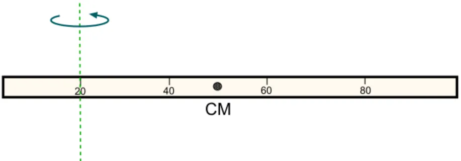
11. Calculate the rotational inertia of a meter stick with mass 0.56 kg, about an axis perpendicular to the stick and located at the 20 cm mark. [HRW5 11-53]
A picture of this rotating system is given in Fig. 1.6. The stick is one meter long (being a meter stick and all that) and we take it to be uniform so that its center of mass is at the 50 cm mark. But the axis of rotation goes through the 20 cm mark.
Now if the axis did pass through the center of mass (perpendicular to the stick), we would know how to find the rotational inertia; from Figure 1.2 we see that it would be
ICM = 121ML2 = 121 (0.56 kg)(1.00 m)2 = 4.7×10⁻²kg·m2
The rotational inertia about our axis will not be the same.
We note that our axis is displaced from the one through the CM by 30 cm. Then the Parallel Axis Theorem (Eq. 1.16) tells us that the moment of inertia about our axis is given by
I =ICM+MD2
where ICM= 4.7×10⁻²kg·m2, as we’ve already found, M is the mass of the rod and D is
the distance the axis is displaced (parallel to itself), namely 30 cm. We get:
I = 4.7×10⁻²kg·m2+ (0.56 kg)(0.30 m)2 = 9.7×10⁻²kg·m2
So the rotational inertia of the stick about the given axis is 0.097 kg·m2.
12. Two masses M and m are connected by a rigid rod of length Land negligible mass as in Fig. 1.7. For an axis perpendicular to the rod, show that the system has the minimum moment of inertia when the axis passes through the center of mass. Show that this moment of inertia is I =µL2, where µ=mM/(m+M).
[Ser4 10-21]
L-x L
x
M m
Figure 1.7: Rotating system for Example 12.
As noted in the figure, let the distance of the axis from the massM bex; then its distance from mass m must be L−x. The definition of the moment of inertia tells us that for this system I = X i miri2 = Mx2+m(L−x)2 =Mx2+m(L2−2Lx+x2) = (M +m)x2−2mLx+mL2
The final expression shows that as a function of x, I is quadratic with a positive coefficient in front of the x2 term. The graph of this function is a parabola which faces up, and it has
a minimum at the value of x for which dI/dx= 0. Solving for this value, we get:
dI
dx = 2(M +m)x−2mL= 0 =⇒ x =
mL
(M +m) (Note, since m
(M+m) is a number between zero and 1 thisis a point between the two masses.)
Now, taking the origin to be at mass M, the coordinate of the center of mass of this system is located at xCM = (M ·0 +m·L) (m+M) = mL (m+M)
so the axis of minimumI does indeed pass through the center of mass. Substituting this value of x into the expression for I we find:
Imin = M mL (M +m) !2 +m L− mL (M +m) !2 = Mm 2L2 (M +m)2 +m L(M +m)−mL (M+m) !2 = Mm 2L2 (M +m)2 +m ML (M +m) !2 = Mm 2L2 +mM2L2 (M +m)2 = mM(m+M) (M +m)2 L 2
1.2. WORKED EXAMPLES 19 30o 1.25 m 0.75 kg T mg 30o (a) (b)
Figure 1.8: The pendulum of Example 13, at a position of 30◦from the vertical. The second picture shows
the forces acting on the ball at the end of the rod.
= mM
(M +m)L
2
Now if we let µ=mM/(M +m) we can write this as
Imin =µL2 .
1.2.7
Torque
13. A small 0.75 kg ball is attached to one end of a 1.25 m long massless rod, and the other end of the rod is hung from a pivot. When the resulting pendulum is
30◦ from the vertical, what is the magnitude of the torque about the pivot? [HRW5
11-61]
Draw a picture of the system! In Fig. 1.8 we show the basic geometry and also the forces which are acting on the ball at the end of the rod. (The rod is massless so no external forces act on it; we only need to worry about the torque produced by the forces acting on the ball.) To calculate the torques due to each force, we need the magnitude of the force, the distance at which it acts from the pivot (here, it is 1.25 m) and the angle between the force and the lever arm (that is, the line joining the pivot to the place where the force acts).
You might think we would want to find the tension T in the rod before calculating the torques, but it is not necessary. The force of the rod on the ball points along the vector r. Soφ = 0 and there is no torque.
The force of gravity makes an angle of 30◦ from the vectorr and since it has magnitude
mg, the magnitude of its torque is
τ =rFsinφ= (1.25 m)(0.75 kg)(9.80sm2) sin 30◦ = 4.6 N·m The net torque has magnitude 4.6 N·m.
C
A
B
O
90o 160o 135oF
AF
CF
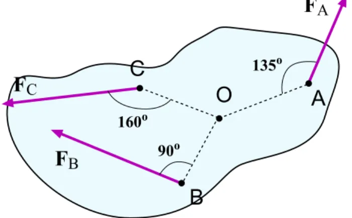
BFigure 1.9: Forces acting on a rotating body in Example 14.
14. The body in Fig. 1.9 is pivoted at O. Three forces act on it in the directions shown on the figure: FA = 10 N at point A, 8.0 m from O; FB = 16 N at point B,
4.0 m from O; and FC = 19 N at point C, 3.0 m from O. What is the net torque
about O? [HRW5 11-64]
Start with the force applied at pointA. HererA= 8.0 m and for our purposes φAcan be
taken as 135◦ or 45◦. Themagnitude of the torque imparted by F
A is |τA|=|rAFAsinφA|=|(8.0 m)(10.0 N) sin(135◦)|= 56.6 N·m
Clearly FA is a force which gives a torque in the counterclockwise (positive, usually) sense,
so we write:
τA = +56.6 N·m
Next, the force applied at B. With rB = 4.0 m and φB = 90◦ we find: |τB|=|rBFBsinφB|=|(4.0 m)(16.0 N) sin(90◦)|= 64.0 N·m
but FB is clearly a force which gives aclockwise (i.e. negative) torque, and so
τB =−64.0 N·m
And finally, the force applied at C. With rC = 3.0 m andφC = 160◦, we have |τC| =|rCFCsinφC|=|(3.0 m)(19.0 N) sin(160◦)|= 19.5 N·m .
One can see that FC gives a counterclockwise torque and so
τC = +19.5 N·m
Now find the total torque!
τnet=
X
τi = (56.6 N·m) + (−64.0 N·m) + (19.5 N·m) = 12.1 N·m
1.2. WORKED EXAMPLES 21
1.2.8
Torque and Angular Acceleration (Newton’s Second Law for
Rotations)
15. When a torque of 32.0 N·m is applied to a certain wheel, the wheel acquires an angular acceleration of 25.0rad
s2 . What is the rotational inertia of the wheel?
[HRW5 11-65]
Torque, angular acceleration and the moment of inertia are related by τ =Iα. Solving for I, we find: I = τ α = 32.0 N·m 25.0rads2 = 1.28 kg·m2
16. A thin spherical shell has a radius of 1.90 m. An applied torque of 960 N·m
imparts to the shell an angular acceleration equal to6.20rad
s2 about an axis through
the center of the shell. (a) What is the rotational inertia of the shell about the axis of rotation? (b) Calculate the mass of the shell. [HRW5 11-69]
(a) From the relation between (net) torque, moment of inertia and angular acceleration,
τ =Iαwe have
I = τ
α
Using the given torque on the shell and its angular acceleration we find that the rotational inertia of the shell is
I = (960 N·m) (6.20rad
s2 )
= 155 kg·m2 .
(b) From Figure 1.3 the moment of inertia for a spherical shell of mass M and radius R
rotating about any diameter is
I = 23MR2
We know I and R so we can solve for the mass of the shell:
M = 3I 2R2 =
3(155 kg·m2)
2(1.90 m)2 = 64.4 kg
17. A wheel of radius 0.20 M is mounted on a frictionless horizontal axis. A massless cord is wrapped around the wheel and attached to a 2.0 kg object that slides on a frictionless surface inclined at 20◦ with the horizontal, as shown in
Fig. 1.10. The object accelerates down the incline at2.0ms2. What is the rotational
inertia of the wheel about its axis of rotation? [HRW5 11-72]
As in most problems of this type, we will find a solution by diagramming the forces which act on each mass and then using Newton’s laws to set up equations. Here there are two masses we need to isolate: The block and the pulley.
20
o2.0 kg
Figure 1.10: Sliding mass on string and pulley, as described in Example 17.
mg
mg sin
q
mg cos
q
T
N
R
T
(a)
(b)
Figure 1.11: (a) Forces on the sliding mass in Example 17. (b) Force (and its position of application on the pulley) in Example 17.
1.2. WORKED EXAMPLES 23 We start with the sliding mass; the forces acting on it are shown in Fig. 1.11(a). There is the downward force of gravity mg on the mass, which we separate into its components:
mgsinθ down the slope and mgcosθ into the plane. There is the normal force N of the surface (outward and perpendicular to the slope) and the tension of the stringT which points up the slope. Since in this problem we take the surface to be frictionless, that’s all.
The block can only move along the slope so the forces perpendicular to the slope must cancel. This gives N = mgcosθ, which we don’t really need! If the acceleration down the slope isa, then adding up the “down–the–slope” forces and using Newton’s 2nd law gives:
mgsinθ−T =ma (1.19)
Now consider the pulley. With the string wrapped around it at a radius R, the action of the string on the wheel is that of a tangential force of magnitude T applied at a distance R, shown in Fig. 1.11(b). The force is perpendicular to the line joining the axle and the point of application so that it gives a (counterclockwise) torque of magnitude rF sinφ =RT. Then the relation between torque and angular acceleration gives:
τ =RT =Iα
where I is the moment of inertia of the wheel.
Now if the string is wrapped around the wheel then as it rolls off the edge of the wheel it must be true that the linear acceleration of any piece of the string is the same as the tangential acceleration of the wheel’s edge, and this is also the same as the acceleration of the mass down the slope. Since the tangential acceleration of the edge of the wheel is
at=Rα, we havea=Rα, or α=a/R. Putting this into the last equation gives
RT =I a
R or T = Ia R2
and this gives an expression for T that we can put into Eq. 1.19. Doing this, we get
mgsinθ− Ia
R2 =ma
Solving for I we find
Ia/R2 =m(gsinθ−a) =⇒ I =mR2(gsinθ−a) a
Now we can plug in the numbers and we get:
I = (2.0 kg)(0.20 m)2((9.80 m s2) sin 20◦ −2.0 m s2) (2.0m s2) = 5.4×10⁻²kg·m2
The rotational inertia of the wheel is 0.054 kg·m2.
18. A block of mass m1 and one of mass m2 are connected by a massless string
m1
m
2
M, R
q
Figure 1.12: Masses joined by string and moving on wedge; pulley (a disk) has mass!
addition, the blocks are allowed to move on a fixed block–wedge of angle θ as in Fig. 1.12. The coefficient of kinetic friction for the motion of either mass on the wedge surface is µk. Determine the acceleration of the two blocks. [Ser4 10-29]
This problem is similar to ones you may have seen in the chapter on force problems. We will solve it in the same way, by drawing a free–body diagram for each mass, writing out Newton’s 2nd Law for each mass and solving the equations. The difference comes from the fact that one of the mass elements in this problem (the pulley!) undergoes rotational motion because of the torques that are exerted on it. It will undergo an angular acceleration which will be related to the common linear acceleration of the two blocks.
We start by noting that for a problem where a string passes over a pulleywhich has mass there will be a different tension for each section of the string. (This differs from the case of the “ideal massless” pulley where the string tension was the same on both sides.) We will see better why this has to be true when we look at the torques acting on the pulley. The part of the string which is connected tom1 will have a tensionT1 and the part of the string
connected tom2 will have a tensionT2.
Then we think about how the blocks are going to move in this situation. As they are connected by a string, the magnitudes of their accelerations will be the same; we can call it
a. We know that regardless of the values of the masses, m1 must move to the right and m2
must move down the slope. (This assumes that friction is not so strong as to prohibit any motion!) And the pulley will be turning clockwise.
Now we can draw the force diagrams for the two blocks; we get the diagrams given in Fig. 1.13. On m1 we have the downward force of gravity m1g and the upward normal force
N1 of the surface; the string pulls to the right with a force of magnitude T1 while there
is a leftward friction force on the block which we denote fk,1. We know that m1 has an
acceleration to right of magnitude a.
The vertical forces on m1 must cancel out, giving N1 = m1g. The kinetic friction force
is then
1.2. WORKED EXAMPLES 25 m1 T1
m
2 m2g T2 fk,2 fk,1 m1g N1 N2 qFigure 1.13: Free–body diagrams for the masses m1 andm2.
Applying Newton’s 2nd law for the horizontal forces gives
T1−fk,1 =T1−µkm1g =m1a
giving us our first “take–home” equation,
T1−µkm1g =m1a (1.20)
We move on to m2. On this mass we have the downward force of gravity, m2g, (which
we show as the sum of its components along the slope and perpendicular to the slope) the normal force from the surface, N2, the force from the string (magnitude T2, directed up the
slope) and the force of kinetic friction, which has magnitude fk,2 and is directedup the slope
because we know that block m2 is movingdown the slope.
The forces (that is, their components) perpendicular to the slope must cancel out, and from our experience with similar problems we can see that this will give
N2 =m2gcosθ .
This gives the magnitude of the force of kinetic friction on m2,
fk,2 =µkN2 =µkm2gcosθ
Now look at the force components onm2in the “down–the–slope” direction. By Newton’s
2nd law they sum to givem
2a, and so we write:
m2gsinθ−T2−fk,2 =m2a
We substitute for fk,2 and get our next “take–home” equation,
m2gsinθ−T2−µkm2gcosθ =m2a (1.21)
The two equations we have found havethreeunknowns: T1,T2 anda. We will never solve
the problem if we don’t get a third equation, and it is the equation of (rotational) motion for the pulley that gives us the last equation.
T
2T
1R
M
Figure 1.14: Forces acting on the pulley in Example 18.
The force diagram for the pulley is given in Fig. 1.14. When the string is wrapped over the pulley and does not slip, it acts to exert a tangential force T2 at the rim of the disk in
one direction and a tangential force T1 in the other direction, as shown.
These forces act at a distance R from the pivot point (the pulley’s axle) and each is perpendicular to the line joining the pivot and the point of application. If we take the clockwise torque as being positive, then the net torque on the disk is
τnet =T2R−T1R = (T2−T1)R .
From the rotational form of the second law, we then have
τnet= (T2−T1)R =Iα
whereIis the moment of inertia of the pulley andαis its angular acceleration in theclockwise sense, since that is how we defined positive torqueτ. We can use a couple other facts before finishing with this equation; we assume the pulley is a uniform disk, and so I is given by
I = 12MR2 .
Also, we know that the linear tangential acceleration of the rim of the disk must be the same as the linear acceleration of the string and also the masses m1 and m2. This gives us:
αR=a =⇒ α=a/R
Putting both of these relations into the τ =Iα equation, we get (T2−T1)R =Iα= 12MR2
a
R
= 12MRa
and so if we cancel a factor of R we have a third equation relating the three unknowns, (T2−T1) = 12Ma (1.22)
1.2. WORKED EXAMPLES 27 m M R m M R v w 50 cm
Figure 1.15: Before and after pictures for a mass–pulley system which starts from rest. Take the pulley to be a uniform disk.
At this point, we have three equations for three unknowns (Eqs. 1.20, 1.21 and 1.22.) The physics part of the problem is done. What remains is the algebra involved in solving for the unknowns T1,T2 and a. Eqs. 1.20 and 1.21 give
T1 =m1a+µkm1g and T2 =−m2a+m2gsinθ−µkm2gcosθ
When we put these into Eq. 1.22 we get:
−(m2+m1)a−µkg(m2cosθ+m1) +m2gsinθ= 12Ma
This containsonly the accelerationa and so we can quickly solve for it. A little rearranging gives
(m1+m2+M/2)a =m2gsinθ−µkg(m1+m2cosθ)
Isolating a and factoring out g gives
a= [m2sinθ−µk(m1+m2cosθ)] (m1 +m2+M/2)
g
for the acceleration of the blocks. This expression can only make sense if µk is not so big
that it makesa negative in this expression.
1.2.9
Work, Energy and Power in Rotational Motion
19. (a) If R = 12 cm, M = 400 g and m = 50 g in Fig. 1.15, find the speed of the block after it has descended 50 cm starting from rest. Solve the problem using energy conservation principles. (b) Repeat (a) with R = 5.0 cm. (Assume the pulley is a uniform disk.) [HRW5 11-77]
(a)If there is no friction in the axle of the pulley then mechanical energy will be conserved as the block descends. The change in total energy between the “before” and “after” pictures in Fig. 1.15 will be zero:
Initially, the block is at rest and so is the pulley, so there isno kinetic energy in the system. In the final picture, the block has some speed v so it has kinetic energy (namely 12mv2) and
the pulley is turning at some angular speedω so that it too has kinetic energy. The kinetic energy of the pulley is Krot = 12Iω2, so that the total kinetic energy in the “after” picture is
Kf = 12mv2+ 12Iω2
We can simplify this expression by realizing that if the string does not slip on the pulley (and it is implied in the set-up that it is wrapped around it, so it doesn’t) then the tangential speed of the edge of the disk is the same as that of the falling mass. This gives ωR=v, or
ω =v/R. Also, assuming that the pulley is a uniform disk, we haveI = 12MR2. Using these
relations we get: Kf = 12mv2+12 1 2MR 2v R 2 = 12mv2+14Mv2= m 2 + M 4 v2
The potential energy of the system changes only from the change in height of the sus-pended massm. Its change in height is ∆y=−0.50 m so that the change in potential energy of the system is
∆U =mg∆y=mg(−0.50 m)
Putting everything into the energy conservation equation we get ∆K+ ∆U = m 2 + M 4 v2+mg(−0.50 m) = 0
which we can use to solve for v since we know all the other quantities:
m 2 + M 4 v2 =mg(0.50 m) = (0.050 kg)(9.80ms2)(0.50 m) = 0.245 J (0.050 kg) 2 + (0.400 kg) 4 ! v2 = (0.125 kg)v2 = 0.245 J v2 = (0.245 J) (0.125 kg) = 1.96 m2 s2 v = 1.4ms
The final speed of the block is v = 1.4ms.
(b) In this part we are asked to find the final speed v if R has a different value. But if we look back at our solution for part (a) we see that we never used the given value of R! (It cancelled out when we wrote out the energy conservation condition in terms of m, M and
1.2. WORKED EXAMPLES 29 10 cm CM Axis 5 cm CM (a) (b) Axis w
Figure 1.16: Cylinder rotating about an off–center axis, in Example 20. (a) is the initial position of the cylinder; (b) shows the cylinder as it moves through its lowest position.
20. A uniform cylinder of radius 10 cm and mass 20 kg is mounted so as to rotate freely about a horizontal axis that is parallel to and 5.0 cm from the central longitudinal axis of the cylinder. (a) What is the rotational inertia of the cylinder about the axis of rotation? (b) If the cylinder is released from rest with its central longitudinal axis at the same height as the axis about which the cylinder rotates, what is the angular speed of the cylinder as it passes through its lower position? (Hint: Use the principle of conservation of energy.) [HRW5 11-84]
(a)First, draw a picture of this system; Fig. 1.16 (a) shows an end–on view of the rotating cylinder. Its symmetry axis is labelled “CM” but its rotational axis is marked “Axis”. The cylinder does not turn about its center! (If it did, its moment of inertia would beI = 12MR2,
but that will not be the case here.) We need some other way of getting I.
There is one special feature about this rotation which will give usI. The rotation takes place about an axis which isparallel to an axis for which wedoknowI, namely the symmetry axis. For that axis, we have ICM = 12MR2 (where M and R are the mass and radius of the
cylinder). Our axis is displaced from that one by a distance D = 5.0 cm = 0.050 m. Then the Parallel Axis Theorem, Eq. 1.16, gives us:
I = ICM+MD2
= 12MR2+MD2
= 12(20 kg)(0.10 m)2+ (20 kg)(0.050 m)2 = 0.15 kg·m2
So the rotational (moment of) inertia of the cylinder about the given axis is 0.15 kg·m2.
(b)The cylinder starts in the position shown Fig. 1.16 (a), that is, with the symmetry axis at the same height as the rotational axis. We know that the force of gravity acts on the cylinder to give it an angular velocity which increases as the cylinder swings downward. We want to know the angular velocity when the center of mass of the cylinder is at its lowest point.
It would be very hard to find the finalω using torques, because t he force of gravity does not act on the cylinder in the same way through the swing. As with similar problems in particle (point–mass) motion, it is easier to useconservation of evergy. If there is no friction in the axis, then total mechanical energy is conserved, which we can write as:
∆E = ∆K+ ∆U = 0
Now, the cylinder starts from rest when it is at the position shown in (a) so that Ki = 0. In
position (b), the cylinder has angular speedω about the axis so that the final kinetic energy is
Kf = 12Iω2
where I is the moment of inertia we found in part (a) of this problem.
There is a change in potential energy of the cylinder because there is a change in height of its center of mass. For an extended object we find the gravitational potential energy by imagining that all the mass is concentrated at the center of mass. Then for the cylinder, since its center of mass has fallen by a distance 5.0 cm (compare picture (a) and picture (b)) we see that the change inU is:
∆U =Mg∆y = (20 kg)(9.80sm2)(−0.050 m) =−9.80 J Plugging everything into our energy conservation equation, we find
∆K+ ∆U = 12Iω2−9.80 J = 0 for which we solve for ω:
ω2 = 2(9.80 J) I = 2(9.80 J) (0.15 kg·m2) = 131 s−2 which gives us ω = 11.4rads
21. A tall, cylinder–shaped chimney falls over when its base is ruptured. Treating the chimney as a thin rod with height h, express the (a) radial and (b) tangential components of the linear acceleration of the top of the chimney as functions of the angle θ made by the chimney with the vertical. (c) At what angleθ does the linear acceleration equal g? [HRW5 11-87]
(a)As suggested in the problem wemodel the falling chimney as a thin rod of height h and mass M which turns about a pivot which is fixed to the ground at one place. (A real falling chimney may behave differently. . . it might break as it falls and the base may move along the ground. Real life is lots more complicated.) The model is shown in Fig. 1.17 (a). The angle θ measures the (instantaneous) angle of the chimney with the vertical. We know that
1.2. WORKED EXAMPLES 31
q
hq
CM h/2 (h/2) cosq M (a) (b)Figure 1.17: (a) The falling chimney described in Example 21. (b) Position of the center of mass of the chimney.
as the chimney falls over (starting from rest) it will lose gravitational potential energy and pick up rotational kinetic energy from its rotation about the pivot. Its angular speed will increase as it falls.
In part (a) we are asked for the radial acceleration of the end of the chimney when the chimney has rotated through an angle θ. That’s just the centripetal acceleration ac of the
top of the chimney, which is given by Eq. 1.12 and since the radius of the circle in which the top moves is h, this is given by
ac=
v2
h =hω
2 .
All that we need to know to computeac is the angular speed of the rod, and for this we
can use energy conservation for the rod as it falls. (Energy conservation is good for finding final speeds!) When the rod is in the initial (vertical) position, it is at rest so it has no kinetic energy. Suppose we measure height from the ground level; then the center of mass of the rod is at a heighth/2 and so the initial gravitational potential energy isMgh
2. So the
initial total energy is
Ei =
Mgh
2
Now suppose the rod has fallen through an angle θ, as shown in Fig. 1.17 (b). If it has angular speed ω at that time, then its kinetic energy is 12Iω2, where I is the moment of
inertia of the rotating chimney. For a uniform rod of lengthh rotating about one end, this is I = 13Mh2, so we have: Kf = 12Iω2 = 12 1 3Mh 2 ω2 = 16Mh2ω2
As for the potential energy in this position, we can see from geometry that the center of mass of the rod is at a height of h
2 cosθ. So the rod’s final potential energy is
Uf =Mg
h
2 cosθ . and its final total mechanical energy is
Ef =Kf +Uf = 16Mh2ω2+Mg
h
q
CM
Mg
Fpivot
q
Figure 1.18: Forces acting on falling rod (chimney)
Energy conservation (we assume that this pivot is frictionless. . . ),Ei =Ef gives
Mgh 2 = 1 6Mh 2ω2+Mgh 2 cosθ which can solve for ω2. Rearranging, we get:
1 6Mh 2ω2 = Mgh 2 (1−cosθ) ω2 = 3g h (1−cosθ)
which we can use in expression forac:
ac=hω2 =h
3g
h(1−cosθ) = 3g(1−cosθ) .
The radial part of the acceleration of the tip of the chimney has this magnitude and is of course directed inward toward the pivot.
(b) From Eq. 1.11, the tangential component of the acceleration for a point on a rotating object a distance h away from the pivot is aT =hα where α is the object’s angular
accel-eration. So we need to find the angular acceleration α of the chimney when it has fallen through an angleθ. We can getαby finding the net torque acting on the rod and then using
τ =Iα.
In Fig. 1.18 we show the forces that act on the rod as it falls, and their points of applica-tion. Gravity (effectively) pulls downward at the center of the rod with a force Mg, and the pivot also exerts a force on the rod. It’s not so clear which direction the latter force points, but in the end it does not matter because we only want thetorques that these forces exert about the pivot point and force of the pivot itself will give no torque.
The force of gravity is applied at a distance h/2 from the pivot. It makes an angle θ
with the line which joins the pivot and application point. Here, it gives a torque in the counter-clockwise sense. So the torque due to gravity is
τ = h
1.2. WORKED EXAMPLES 33 and this is also thetotal (counter-clockwise) torque because the force of the pivot gives none. Then τnet =Iα gives us
h
2Mgsinθ =Iα
where I is the moment of inertia of the rod. For a uniform rod of length h rotating about one end, it isI = 13Mh2 so we get:
h
2Mgsinθ =
1 3Mh
2α
Some algebra gives us:
α= 3g 2hsinθ
And at last we find the tangential acceleration of the end of the chimney:
aT =hα =h
3g
2hsinθ =
3
2gsinθ .
The answers to (a) and (b) do not depend on the mass M of the chimney.
(c) We want to know at what angle the linear (i.e. the tangential) acceleration of the chimney–top is equal to g. Using our answer from part (b), we have the condition:
3 2gsinθ=g Solve for θ: sinθ = 23 =⇒ θ = sin−12 3 = 41.8◦