In a modern society a lot of digital content is being uploaded and downloaded from different digital services using wireless access. The increasing interest in high date rate communications brings new challenges for researchers. Reconfigurable antennas, with the ability to control their properties according to the changes in the
environment, can help to improve the overall system performance and increase the system capacity. Furthermore, studies of radio wave propagation and channel
modeling can help in careful planning and deployment of the wireless communication systems. In this thesis both of these relevant research topics are addressed.
A alt o-D D 1 51 /2 01 6
9HSTF
MG*agj
ebi+
ISBN 978-952-60-6941-8 (printed) ISBN 978-952-60-6940-1 (pdf) ISSN-L 1799-4934 ISSN 1799-4934 (printed) ISSN 1799-4942 (pdf) Aalto UniversitySchool of Electrical Engineering
Department of Radio Science and Engineering www.aalto.fi BUSINESS + ECONOMY ART + DESIGN + ARCHITECTURE SCIENCE + TECHNOLOGY CROSSOVER DOCTORAL DISSERTATIONS Va sil ii S em kin R ec on fig ur ab le a nte nn as an d r ad io w av e p ro pa ga tio n a t m illi m ete r-w av e f re qu en cie s A alt o U n ive rs ity 2016
Department of Radio Science and Engineering
Reconfigurable antennas
and radio wave propagation
at millimeter-wave
frequencies
Vasilii Semkin
DOCTORAL DISSERTATIONS
Aalto University publication series DOCTORAL DISSERTATIONS 151/2016
Reconfigurable antennas and radio
wave propagation at millimeter-wave
frequencies
Vasilii Semkin
A doctoral dissertation completed for the degree of Doctor of Science (Technology) to be defended, with the permission of the Aalto University School of Electrical Engineering, at a public examination held at the lecture hall S4 of the school on 2 September 2016 at 12.
Aalto University
School of Electrical Engineering
Supervising professor
Prof. Antti V. Räisänen, Aalto University, Finland Thesis advisors
Prof. Dr.-Ing. Thomas Kürner, Technische Universität Braunschweig, Germany Dr. Juha Ala-Laurinaho, Aalto University, Finland
Preliminary examiners
Prof. Dr.-Ing. Thomas Zwick, Karlsruher Institut für Technologie, Germany Prof. Özlem Aydin Civi, Middle East Technical University, Turkey
Opponent
Prof. Lluís Jofre, Universitat Politècnica de Catalunya, Spain
Aalto University publication series DOCTORAL DISSERTATIONS 151/2016 © Vasilii Semkin ISBN 978-952-60-6941-8 (printed) ISBN 978-952-60-6940-1 (pdf) ISSN-L 1799-4934 ISSN 1799-4934 (printed) ISSN 1799-4942 (pdf) http://urn.fi/URN:ISBN:978-952-60-6940-1 Unigrafia Oy Helsinki 2016 Finland
Abstract
Aalto University, P.O. Box 11000, FI-00076 Aalto www.aalto.fiAuthor Vasilii Semkin
Name of the doctoral dissertation
Reconfigurable antennas and radio wave propagation at millimeter-wave frequencies Publisher School of Electrical Engineering
Unit Department of Radio Science and Engineering
Series Aalto University publication series DOCTORAL DISSERTATIONS 151/2016 Field of research Radio Engineering
Manuscript submitted 21 April 2016 Date of the defence 2 September 2016 Permission to publish granted (date) 13 June 2016 Language English Monograph Article dissertation Essay dissertation Abstract
For the last decades we have been witnessing the evolution of wireless radio networks. Since new devices appear and the mobile traffic, as well as the number of users, grows rapidly, there is a great demand in high capacity communications with better coverage, high transmission quality, and more efficient use of the radio spectrum. In this thesis, reconfigurable antennas at micro- and millimeter-wave frequencies and peculiar properties of radio wave propagation at mm-wave frequencies are studied.
Reconfigurable antennas can improve radio link performance. Recently, many different concepts have been developed in the reconfigurable antenna design to control the antenna bandwidth, resonant frequency, polarization, and radiation properties. In the first part of the thesis, we investigate mechanically tunable antennas operating at microwave frequencies with the ability to change the shape of the conductor element and, consequently, to control the radiation properties of the antenna. Also in the first part, we study conformal antenna arrays for 60 GHz applications based on cylindrical structures. Beam switching technology is implemented by realizing several antenna arrays around the cylinder with a switching network. Scanning angles of +34˚/-32˚ are achieved.
Moreover, it is vital to study radio wave propagation peculiarities at mm-wave frequencies in indoor and outdoor environments to be able to deploy wireless networks effectively. The propagation part of the thesis focuses on several aspects. First, we investigate how the estimation of optimum antenna configurations in indoor environment can be done using realistic propagation models at 60 GHz. Ray tracing simulations are performed and realistic human blockage models are considered. Second, we present the results from a measurement campaign where reflection and scattering properties of two different built surfaces are studied in the millimeter-wave E-band (71-76 and 81-86 GHz). Next, we present a geometry based channel model for a street canyon scenario, using angular-domain measurement results to calculate realistic power angular spectra in the azimuth and elevation planes. Then, we evaluate propagation effects on the radio channel on the rooftop of the buildings by measurements and simulations. We have used unmanned aerial vehicles and photogrammetry technique to create a highly accurate 3D model of the environment. Based on a comparison of the measured and simulated power delay profiles, we show that the highly accurate 3D models are beneficial in radio wave propagation planning at mm-wave frequencies instead of using simple geometrical models.
Keywords Reconfigurable antennas, beam switching, high-capacity communications, radio wave propagation, mm-wave, ray-tracing
ISBN (printed) 978-952-60-6941-8 ISBN (pdf) 978-952-60-6940-1
ISSN-L 1799-4934 ISSN (printed) 1799-4934 ISSN (pdf) 1799-4942 Location of publisher Helsinki Location of printing Helsinki Year 2016
5
Preface
The doctoral thesis has been carried out in the Department of Radio Science and Engineering at Aalto University, School of Electrical Engineering. I am very grateful to my first supervisor, late Prof. Pertti Vainikainen, who gave me an opportunity to become a PhD student in his group, for his invaluable support and guidance in my doctoral studies and fruitful discussions during which I have learnt a lot about radio communications. I am very thankful to Prof. Antti Räisänen who became my supervisor in August 2012 for his great help and support during my doctoral studies.
I want to thank my former instructors Dr. Veli-Matti Kolmonen and Dr. Mikko Kyrö for their priceless advices, ideas for the research work and help during my studies. I would like to thank my instructors Prof. Thomas Kürner and Dr. Juha Ala-Laurinaho for their useful advices and discussions. I would also like to thank Prof. Sergei Tretyakov for sharing his ideas and experience, which helped to improve the results of this work.
I express my gratitude to Prof. Cyril Luxey, Associate Prof. Fabien Ferrero and Dr. Aimeric Bisognin, for their instructions during my research visits to Nice in 2012 and 2014 and also for their cooperation during my doctoral research. Furthermore, my thanks go to Prof. Thomas Kürner and Dr. Martin Jacob for hosting and instructing me during my research visit to Braunschweig in 2013. I would like to thank my former colleague Oleg Platonov for numerous interesting discussions and our collaboration. Also my current and former colleagues at the Department of Radio Science and Engineering deserve warm thanks for their support and informal discussions. Thanks to Dr. Risto Valkonen, Dr. Dmitry Morits, Dr. Andrey Generalov, Lic. Sc. Irina Nefedova, Dr. Igor Nefedov, Dr. Ilya Anoshkin, Prof. Katsuyuki Haneda, Dr. Aki Karttunen, Mr. Reza Naderpour, Mr. Usman Virk, Mr. Jan Järveläinen, Dr. Joni Vehmas, Mr. Kimmo Rasilainen, and many others. I would also like to thank my co-author Mr. Dmitrii Solomitckii from Tampere University of Technology.
I would like to thank the pre-examiners, Prof. Thomas Zwick and Prof. Özlem Aydin Civi, for their valuable comments and suggestions for improving this thesis.
This thesis work was supported by the GETA Graduate School, as well as SMARAD (Academy of Finland CoE in Smart Radios and Wireless Research), and Aalto ELEC doctoral school. I am grateful for the personal grants awarded
6
by the TES (Tekniikan edistämissäätiö), Nokia Foundation, Aalto University, Helsinki University of Technology Research Foundation and Walter Ahlström foundation during my research.
Thanks to my parents Marina and Viktor, and my grandparents Vladimir and Rimma for the support and encouragement.
Finally, I send my warmest thanks to my wife Karina for your love, patience and support during last years of my studies.
Espoo, July 26, 2016,
7
Contents
Preface ... 5 List of Publications ... 9 Author’s Contribution ... 11 List of abbreviations ... 13 List of symbols ... 15 1. Introduction ... 171.1. Objectives of this work ... 18
1.2. Organization and contributions of the thesis ... 18
2. Reconfigurable antennas for smart radio systems ... 21
2.1. Antenna parameters ... 23
2.2. Millimeter-wave measurement setup ... 26
2.3. Reconfigurable antennas ... 27
2.4. Contributions of the thesis ... 28
2.4.1. Microfluidic antenna array ... 28
2.4.2. Conformal antenna arrays... 29
3. Radio wave propagation at mm-wave frequencies ... 33
3.1. Ray-optical wave propagation ... 34
3.2. Propagation mechanisms ... 36
3.2.1. Free-space propagation ... 36
3.2.2. Ray reflection and transmission... 36
3.2.3. Scattering from rough surfaces ... 37
3.2.4. Diffraction and human blockage models ... 38
3.3. Characterization of radio wave propagation at mm-wave frequencies ... 39
3.3.1. Ray tracing techniques... 39
3.3.2. Photogrammetry and its applicability for ray launching simulations ... 40
3.3.3. Channel modeling of an urban street canyon ...41
3.4. Contributions of the thesis ... 42
8
3.4.2. Characterization of scattering patterns at mm-wave frequencies .. 44
3.4.3. E-band propagation channel measurements ... 45
3.4.4. Characterization of radio links using 3D models... 46
4. Summary of publications ... 49
5. Conclusions and future work ... 51
References ... 53
9
List of Publications
This thesis consists of an overview of the following publications which are referred to in the text by their Roman numerals.
I V. Semkin, O. Platonov, M. Kyrö, and A. V. Räisänen, “Liquid metal patch antenna and antenna array for WLAN applications,” Microwave and Optical Technology Letters, vol. 56, no. 10, pp. 2462-2464, Oct. 2014.
II V. Semkin, A. Bisognin, M. Kyrö, V.-M. Kolmonen, C. Luxey, F. Ferrero, F. Devillers, and A. V. Räisänen, “Conformal antenna array for millimeter-wave communications: performance evaluation,” International Journal of Wireless and Microwave Technologies, 2015, available online, doi:10.1017/S1759078715001282.
III V. Semkin, F. Ferrero, A. Bisognin, J. Ala-Laurinaho, C. Luxey, F. Devillers, and A. V. Räisänen, “Beam switching conformal antenna array for mm-wave communications,” IEEE Antennas and Wireless Propagation Letters, vol. 15, pp. 28-31, 2016.
IV V. Semkin, M. Jacob, T. Kürner, A. Bisognin, F. Ferrero, C. Luxey, and A. V. Räisänen, “Estimation of optimum antenna configurations supported by realistic propagation models at 60 GHz,” European Conference on Antennas and Propag. (EuCAP2014), The Hague, The Netherlands, Apr. 2014, pp. 3434-3438.
V M. Kyrö, V. Semkin, and V.-M. Kolmonen, “Empirical characterization of scattering pattern of built surfaces at mm-wave frequencies,” European Conference on Antennas and Propag. (EuCAP2013), Gothenburg, Sweden, Apr. 2013, pp. 112-115.
VI V. Semkin, U. Virk, A. Karttunen, K. Haneda, and A. V. Räisänen, “E-band propagation channel measurements in an urban street canyon,” The 9th European Conference on Antennas and Propagation (EuCAP 2015), Lisbon, Portugal, Apr. 2015.
10
VII V. Semkin, D. Solomitckii, R. Naderpour, S. Andreev, Y. Koucheryavy, and A.V. Räisänen, “Characterization of radio links at 60 GHz using simple geometrical and highly accurate 3D models,” submitted to IEEE Transactions on Vehicular Technology (original manuscript submitted 21.04.2016, under major revision at the time of printing the thesis), 2016.
11
Author’s Contribution
I: “Liquid metal patch antenna and antenna array for WLAN applications”
The paper is based on the author’s idea, and the author was responsible for manufacturing the antenna and for the content of the paper. Mr. Platonov assisted in the measurements. Dr. Kyrö and Prof. Räisänen supervised the work.
II: “Conformal antenna array for millimeter-wave communications: performance evaluation”
The author designed the antenna array and had the main responsibility for the manuscript. Dr. Kolmonen proposed the initial idea of the paper and supervised the work. Mr. Bisognin and Prof. Ferrero performed the measurements. Mr. Devillers manufactured the supporting structures for the antenna array. Prof. Luxey and Prof. Räisänen supervised the work.
III: “Beam switching conformal antenna array for mm-wave communications”
The main idea belongs to the author. The antenna array with the switch was designed by the author. The author was assisting in measurements, carried out by Prof. Ferrero and Dr. Bisognin. Mr. Devillers manufactured the supporting structures for the antenna array. Dr. Ala-Laurinaho, Prof. Luxey, and Prof. Räisänen supervised the work.
IV: “Estimation of optimum antenna configurations supported by realistic propagation models at 60 GHz”
The paper is based on the author’s and Dr. Jacob’s idea and the author was responsible for the ray tracing simulations and preparation of the manuscript. The author assisted Dr. Jacob in the development of a realistic propagation model. Prof. Kürner, Prof. Ferrero, Prof. Luxey, and Prof. Räisänen supervised the work.
12
V: “Empirical characterization of scattering pattern of built surfaces at mm-wave frequencies”
Dr. Kyrö had the main responsibility for developing the content of the paper. The author and Dr. Kyrö were the main responsible persons for carrying out the measurements. Dr. Kolmonen supervised the work.
VI: “E-band propagation channel measurements in an urban street canyon”
The author performed channel measurements with Mr. Virk and Dr. Karttunen. The author was responsible for preparation of the paper. The work was instructed by Prof. Haneda and Prof. Räisänen.
VII: “Characterization of radio links at 60 GHz using simple
geometrical and highly accurate 3D models”
The author was responsible for developing the idea and content of the paper. The author, Mr. Solomotckii, and Mr. Naderpour prepared the manuscript. The measurements were performed by the author with the assistance of Mr. Naderpour. The highly accurate 3D model was created by the author. The author assisted Mr. Solomitckii in the shooting-and-bouncing ray simulations. Dr. Andreev, Prof. Koucheryavy, and Prof. Räisänen supervised the work.
13
List of abbreviations
2D Two-dimensional
3D Three-dimensional
APC Antenna pattern comparison technique
AUT Antenna under test
CPW Coplanar waveguide
D/A control Digital/analog control
DC Direct current
FCC United States Federal Communication
Commissions
GO Geometrical optics
GTD Geometrical theory of diffraction
GSG Ground-Signal-Ground
HD High definition
HFSS High frequency structure simulator
HPBW Half power beam width
IC Integrated circuit
IEEE Institute of Electrical and Electronics Engineers
IM Image method
LIDAR Light Identification Detection And Ranging
LOS Line-of-sight
MEMS Microelectromechanical system
MKE Multiple knife edge
mm-wave Millimeter wave
PAS Power angular spectrum
14
PDP Power delay profile
PIN-diode Diode with an undoped intrinsic semiconductor region between n- and p-type regions
PTFE Polytetrafluoroethylene RF Radio frequency RL Ray launching RT Ray tracing Rx Receiver SBR Shooting-and-bouncing ray
SP3T Single pole three throw (switch)
Tx Transmitter
UAV Unmanned aerial vehicle
UTD Uniform theory of diffraction
VNA Vector network analyzer
15
List of symbols
c Speed of light
dA, dA0 Cross section areas
ܦఏǡ ܦఝ Directivity
E Electric field
fr Resonant frequency
Greal Realized antenna gain
Gr Receiving antenna gain
Gt Transmitting antenna gain
h Thickness of a substrate
H Magnetic field
Lfs Free space loss
Prad Radiated power
Pr Received power
Pt Transmitted power
R Distance between antennas
s Distance between cross sections in an astigmatic
tube of rays
S11, S12, S21, S22 Scattering parameters
U, U0 Radiation power density
W Patch width
α Unideal factor in the scan loss
β Propagation constant in free space
εr Relative permittivity
16
η0 Total antenna efficiency
θ Spherical coordinate θi Angle of incidence θr Angle of reflection θs Scan angle θt Angle of transmission λ Wavelength
ρ Curvature radius of the wave front
ρrough Effective reflection coefficient
ρsmooth Reflection coefficient from a smooth surface
σ Deviation of height distribution
17
1. Introduction
Since the first wireless systems appeared about 100 years ago, the data rates have dramatically increased. The rapid increase of mobile data transfer and appearance of new devices such as smartphones and tablets create increasing demands for the system designers. As the wireless access is nowadays considered as a reliable service, totally new usage scenarios have been invented at the same time as well. Many of these usage scenarios require responsive and reliable high-capacity communication systems. This goal is particularly challenging in densely populated areas, such as city centers. In these areas, the wireless systems have to be able to compensate for the increased interference levels and the core network has to be able to provide sufficient amount of throughput so that all customers can be served. It is difficult to achieve high data rates with the conventional radio systems because of limited bandwidth and limitations on the transmission power.
Wireless networks operating at millimeter-wave (mm-wave) frequencies are one of the promising solutions to support multi Gbit/s communications, thanks to the availability of a wide frequency spectrum. Moreover, due to the short wavelength, antennas operating at mm-wave frequencies can be integrated with the receivers and transmitters. The millimeter wave region corresponds to frequencies between 30 and 300 GHz with the wavelengths between 10 to 1 mm, respectively. In the wireless communications usually the term of mm-wave frequencies matches several bands of spectrum, such as 38, 60, 70-90, and 94 GHz. Also, the E-band (which consists of two frequency bands: 71-76 and 81-86 GHz) is already allocated for fixed point-to-point radio links [FCC2005, ETSI2006]. The main advantage of using such radio links is cost reduction comparing to the fiber optics systems. However, it is essential to know the peculiarities of mm-wave propagation since radio links can be affected by the propagation effects at these frequencies. At mm-wave frequencies the resonances of oxygen and water vapor molecules bring in additional losses and precipitation can cause high attenuation [FCC1997]. These effects mostly limit the use of certain mm-wave frequencies (especially around 60 GHz) to indoor scenarios. Compared with the lower frequency bands, millimeter wave radio signals can propagate only over shorter distances in the atmosphere. This is not a real drawback of such systems because they can provide high-speed communications for densely packed areas with more efficient spectrum utilization. One example of applications that require high data rate transmission in indoor environment is uncompressed high-quality video streaming. These communication systems are expected to provide more
18
than 1 Gbit/s data rate at distances up to 10 m. The 60 GHz frequency with a free-space wavelength of 5 mm makes the antenna structure physically compact. A bandwidth of 9 GHz available in the 60 GHz range makes co-channel interference less probable. High gain antenna arrays can be used to compensate for large free space losses. For indoor radio links human blockage can have a high impact on the radio channel [Singh2009, Jacob2011]. Smart antennas with high gain and beam steering capabilities can help to overcome the dynamic human blockage effects.
1.1. Objectives of this work
In a modern society a lot of digital content is being uploaded and downloaded from different digital services using wireless access. The increasing interest in high date rate communications brings new challenges for researchers. Reconfigurable antennas, with the ability to control their properties according to the changes in the environment, can help to improve the overall system performance and increase the system capacity. Furthermore, studies of radio wave propagation and channel modeling can help in careful planning and deployment of the wireless communication systems. In this thesis both of these relevant research topics are addressed. The main objectives of this thesis are:
x To investigate the concept of reconfigurable microfluidic antennas for the usage in wireless local area networks.
x To develop a conformal antenna array operating at mm-wave frequencies, investigate its radiation performance and implement beam switching technology.
x To study the ray tracing method in order to envisage optimum antenna configurations for a specific environment based on the requirements for the communication system.
x To study radio wave propagation in the E-band in outdoor environments, including reflection and scattering properties of built surfaces and angular distribution of scatterers.
x To validate the applicability of highly accurate models of the environment for utilization in shooting-and-bouncing ray simulations.
1.2. Organization and contributions of the thesis
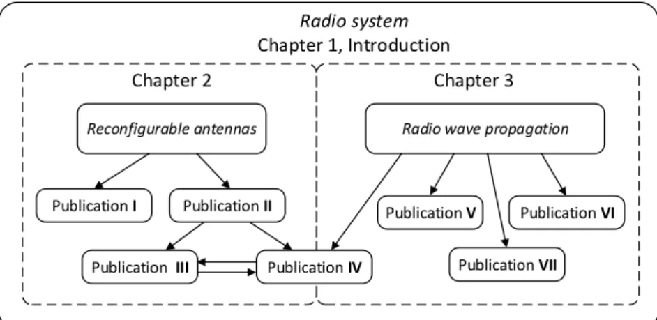
The structure of the thesis is illustrated in Figure 1.1. The figure presents the whole radio system, however, the thesis concentrates only on two topics: reconfigurable antennas for micro- and mm-wave communications (Chapter 2), and characterization of radio wave propagation at mm-wave frequencies (Chapter 3).
19
Radio system
Chapter 1, Introduction
Reconfigurable antennas Radio wave propagation
Publication I Publication III Publication V Publication VI Publication VII Chapter 2 Chapter 3 Publication IV Publication II
Figure 1.1. Illustration of the thesis content.
Chapter 2 of the thesis discusses different types of reconfigurable antennas. We investigate the applicability of various multi-element antenna configurations and manufacturing processes of these antennas for millimeter wave frequencies. A reconfigurable antenna is an antenna capable to modify dynamically its properties, e.g. the operational frequency or radiation pattern. Antennas with the ability to reconfigure their radiation patterns can be beneficial in high data rate wireless communication systems for frequency reuse and for mitigating interference. In the first part of Chapter 2, antenna structures operating at 5.8 GHz with the use of liquid metals such as gallium are investigated. Using the properties of liquid metals can help us to avoid the main disadvantages of mechanically-actuated reconfigurable antennas, for example, mechanical failures. Another advantage is that antenna arrays with liquid metal, forming the radiating part on a flexible substrate, can be deformable and mechanically tunable. Tunability and beam-steering capability can also be achieved by injecting liquid metal into appropriate channels in the antenna structure. Radiation properties of the antenna can be controlled and these antennas can dynamically adapt to the changes in the communication channel or in the system requirements.
Antenna operating at 5.8 GHz frequency can be used in wireless local area network (WLAN) applications to achieve higher data rate communications compared to the usual 2.4 GHz frequency band. The prototype of a microfluidic antenna was developed and measured in [I]. In the second part of Chapter 2, conformal antennas are investigated. Conformal antennas can have large impact on high data rate communications. One of the main advantages of using these antenna structures is that they replicate the form of an object on which they are placed. This can be a great benefit for mobile devices, which can have a curved shape, or in the flexible electronics. Conformal antennas can have high gain and quasi-omnidirectional radiation patterns for omnidirectional coverage, which is essential for mobile handheld or wearable devices. Beam steering or beam switching can be realized using such antenna structures. The performance of conformal antenna arrays for 60 GHz applications based on cylindrical structures were studied in paper [II].
20
Conformal antenna arrays with a beam switching network were developed and characterized; in [III].
Chapter 3 of the thesis deals with radio wave propagation modeling and channel measurements at mm-wave frequencies in outdoor and indoor environments. Publication [IV] relates to Chapter 2 and Chapter 3. Results obtained in [IV] indicate that preliminary information of optimum antenna configurations, in a conference room scenario, can be obtained by ray tracing simulations. Reconfigurable conformal antennas developed in [II] and described in the first part of the thesis are used in the ray tracing simulations. Moreover, it is shown that the first estimations of the optimum antenna parameters can be done approximating the antenna radiation patterns with Gaussian beam antenna patterns. Human blockage, which is one of the main attenuation factors at 60 GHz, is considered.
In order to deploy mobile networks effectively it is essential to know the characteristics of radio wave propagation in a certain environment. The information received from measurements can be used for implementing accurate channel models in realistic environments. Modeling radio wave propagation at millimeter-wave frequencies in urban environments requires knowledge of the reflection and scattering properties of built surfaces. The measured data has been used for characterization of such properties for brick and glass walls in [V].
E-band radio wave propagation in a street canyon scenario is characterized in [VI]. Based on the measurement results, an existing 2D channel model [Kyrö2012] is extended to a 3D model by using the angular distributions of scatterers. Realistic power angular spectra can be calculated using the presented channel model.
Finally, a measurement campaign has been carried out to evaluate propagation effects on a rooftop-to-rooftop radio channel. Two 3D models, obtained with different technologies, are presented: a simple geometrical model and a close-range photogrammetry model, which replicate the building geometry. The analysis is based on shooting-and-bouncing ray simulations and it aims at describing the feasibility of using highly accurate models of the environment in order to predict radio wave propagation effects at two different frequency bands [VII].
21
2. Reconfigurable antennas for smart
radio systems
The 1st generation networks appeared in 1980’s, they were analog and allowed only voice transmission. The first GSM network was launched in Finland by Radiolinja company in 1991. This digital cellular network of second generation (2G) allowed users to make calls and send text messages. Next, 2G system evolved into 2.5G and 2.75G with improvements in the data rates (56 kbit/s for 2.5G and 236 kbit/s for 2.75G, respectively) and services like Wireless Application Protocol (WAP), Multimedia messages (MMS) and Enhanced Data Rates for GSM Evolution (EDGE) technology were added [Lamba2012]. In 2002, 3G mobile networks based on Universal Mobile Telecommunication System (UMTS) technology appeared. This technology allows transmitting 14 Mbit/s of data. Later, 3G networks were developed to 3.5G and the data rates were increased up to 168 Mbit/s. LTE technology in the 4G mobile networks provides up to 337 Mbit/s of downlink speed. At the current time, 5G standard is being developed [Huawei2013, Bogale2016]. The primary goal is to support up to 1 Gbit/s for many users simultaneously. The main reasons for developing mobile networks are the increase in the data rates, appearances of new services and exponential growth of the number of connected devices. In Fig. 2.1 the forecast of the mobile traffic growth is presented [Cisco2016]. Mobile traffic data rates will exceed 30 Exabyte (1 Exabyte = 1 million of terabytes) per month by 2020. As can be seen, there is a great demand in high capacity communication systems which could support multi Gbit/s communications in the nearest future.
22
One example of the applications that require such high data rates is wireless transmission of high quality uncompressed video signal. Reconfigurable antennas can be one of the key elements to support high data rate communications. These antennas can significantly enhance radio system performance. Moreover, such antennas can be used in automotive radars, where it is necessary to steer the beam of the antenna and change its shape from omnidirectional to pencil beam. Reconfigurable antennas can also be used in satellite communications and airplane radars.
The history of reconfigurable antennas began in 1930’s, when a two element antenna array was developed with the ability to steer nulls of the radiation pattern by using a phase changer in order to determine the direction of signal arriving [Friis1934], which then led to a steerable antenna [Friis1937]. Later, a multibeam antenna was proposed in [Simmons1966, Matthews1979].
These antennas can be classified into the following categories, by the type of reconfiguration:
x frequency reconfigurability – ability to cover different frequency bands;
x pattern reconfigurability – transformation from isotropic to very narrow antenna beam or pointing beam of the antennas to different directions;
x polarization reconfigurability – antenna elements can radiate waves of different polarizations;
x hybrid reconfigurability – which is the combination of previously mentioned three techniques.
Compared with conventional omnidirectional and fixed beam antennas, reconfigurable antennas can provide: larger coverage area, frequency reuse with fewer base stations, less probable co-channel interference, increased data rates, and, consequently, overall system capacity.
Recently, many different concepts have been developed in the reconfigurable antenna design to control the antenna bandwidth, resonant frequency, polarization, and radiation properties. Antennas using radio-frequency microelectromechanical systems, or RF MEMS, [Brown1998, Chiao1999, Rebeiz2003, Erdil2007, Kingsley2007, Civi2011], PIN-diodes [Nikolaou2006, Kim2008, De Luis2009, Di Palma2015], and varactors [Behdad2006, White2009, Cure2014] can be considered as electrically reconfigurable. PIN-diodes or varactors are faster comparing to RF MEMS. The switching time of the PIN diode is 1-100 ns, and for the RF MEMS it is in the range of 1-300 μs [Rebeiz2003], which can be too large in some applications. However, PIN-diodes have high losses and require rather high bias voltages for their operation. Optically reconfigurable antennas utilize photoconductive switching elements [Pringle2004, Tawk2010]. In Table 1 an overview of the technologies, which can be used in reconfigurable antenna structures, is presented [Hum2014].
23
Table 1.Technologies for the implementation of reconfigurable reflect arrays and reconfigurable array lens (“-”, “0”, and “/” symbols refer to good, neutral, and poor, respectively), based on [Hum2014]. Type Tec hnology Reli abil ity In tegrat ion D/ A c ont rol C omplexi ty (c os t) Los s (mi crowav e/ T Hz ) Bias pow er co ns um ption Line arit y Sw itc hing ti me Lumped elements PIN diodes
-
/
D-
/
/
/
/
0 -Varactor diodes-
/
A-
/
/
/
-
/
-RF-MEMS 0-
D-
-
/
0-
-
0 Hybrid Ferro-electric thin film 0-
A 0 0/
/
-
0 -Tunable materials Liquid crystal 0 0 A 0/
/
-
0 0/
Graphene/
-
A 0/
/
-
-
/
- Photo-conductive 0/
A 0/
/
/
/
/
-Mechanical Fluidic 0/
A 0 0/
-
-
0/
Micromotors/
0 A/
-
0-
/
In this work, mechanically tunable antennas and antenna arrays using PIN-diode switches with the ability to reconfigure radiation characteristics are considered. Such antennas are of interest because of their ability to direct the beam towards the intended direction, which leads to power savings and improved signal to noise ratio. The antenna part of the thesis is dedicated to microfluidic antennas operating at 5.8 GHz and conformal antennas designed for the 60 GHz frequency range.
2.1. Antenna parameters
To describe antenna performance it is necessary to define various parameters and the relevant ones are described in this chapter. These parameters can be used for all antenna types independently on the antenna structure or operating frequency. First, the antenna radiation pattern is defined as a spatial distribution of a quantity that characterizes the electromagnetic field radiated by the antenna. The radiation pattern is defined in the far-field region and presented as a function of directional coordinates. The radiation pattern is usually characterized by the width of the main beam at half of its maximum power level, i.e. by the half power beamwidth (HPBW).
24
The antenna directivity D(θ, φ) is the ratio of the radiation intensity in a given direction from the antenna over the intensity averaged over all directions [IEEE1993]. The gain of the antenna G(θ, φ) combines the directivity and radiation efficiency of the antenna, which is the ratio between the radiated and accepted powers. The realized gain of the antenna comprises also mismatch losses [Balanis2005]. The directivity can be calculated as
ܦሺߠǡ ߮ሻ ൌ ܦఏሺߠǡ ߮ሻ ܦఝሺߠǡ ߮ሻ (2.1)
while the partial directivities Dθ and Dφ are defined as ܦఏൌሺସగഇሺఏǡఝሻ
౨ౚሻഇାሺ౨ౚሻക (2.2)
ܦఝൌ ସగകሺఏǡఝሻ
ሺ౨ౚሻഇାሺ౨ౚሻക (2.3)
where Uθand Uφare the radiation intensities in a given direction contained in
orthogonal θ and φ components; (Prad)θ and (Prad)φ are the power in all
directions contained in θand φcomponents.
The realized gain of an antenna can be calculated as
ܩ୰ୣୟ୪ൌ ߟܦሺߠǡ ߮ሻ (2.4)
where ߟ is the total antenna efficiency.
Link budget calculation can be performed to estimate necessary antenna gains or the maximum distance between the antennas when the connection is possible. The frequency and distance dependence of the loss between two antennas in free space can be expressed by the Friis transmission equation:
ೝ ൌ ܩ௧ܩ
ଵ
ಷೄ (2.5)
where Pr is received power, Pt is the transmit power, Gt is the transmitting
antenna gain, Gr is the receiving antenna gain, and LFS is free space loss
[Friis1946]. The free space loss is defined as: ଵ
ಷೄൌ ሺ ఒ ସగோሻ
ଶ (2.6)
where λ is the wavelength and R is the distance between the antennas. However, the atmospheric losses are not included in (2.5), which can have high impact on the propagation loss. Based on (2.5) and estimated atmospheric losses the necessary antenna gains can be calculated in the defined scenario if the distance between transmitter and receiver is known, assuming a pure line-of-sight (LOS) propagation channel.
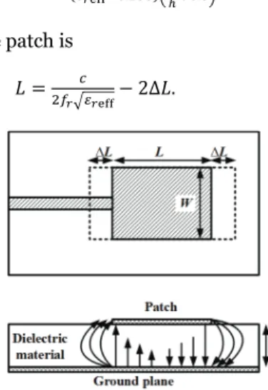
In applications where the weight, cost, size, and performance are essential parameters, low profile antennas are often required. Microstrip antennas are good candidates since they can meet all the requirements mentioned above [Deschamps1953, Gutton1955, Munson1972, Howell1975, Pozar1992]. A microstrip antenna consists of a conductive patch and a ground plane
25 separated by a dielectric layer. Radiation from the patch is similar to the radiation from two slots, at the left and right edges of the patch, where the slot is the narrow gap between the patch and the ground plane. Due to the fringing effects, the electrical length is larger than the physical one. The increase in effective patch length and E-field of the patch antenna is illustrated in Fig. 2.2.
The radiation patch element can have various shapes, e.g. square, rectangular, circular, elliptical, etc. There are several methods to feed patch antennas: microstrip line, coaxial cable, aperture coupling, and proximity coupling. In this thesis, microstrip line feeding technique for the developed rectangular patch antenna arrays is used. Rectangular patch element dimensions can be calculated by the transmission-line model [Hammerstad1975, Bahl1980, Balanis2005]. The design procedure can be described as follows. First, we estimate the patch width
ܹ ൌ
ଶೝට ଶ
ఌೝାଵ (2.7)
where c is the speed of light, fr is the resonance frequency, εr is therelative
permittivity. Next, the effective relative permittivity can be calculated as
ߝୣൌఌೝାଵ ଶ ఌೝିଵ ଶ ቂͳ ͳʹ ௐቃ ିଵȀଶ (2.8)
where h is the thickness of the substrate. After that the relation for the normalized extension of the length can be found:
ο
ൌ ͲǤͶͳʹ
ሺఌೝାǤଷሻቀೈାǤଶସቁ
ሺఌೝିǤଶହ଼ሻቀೈାǤ଼ቁ (2.9) The actual length of the patch is
ܮ ൌ
ଶೝඥఌೝെ ʹȟܮǤ (2.10)
26
2.2. Millimeter-wave measurement setup
The measurement of the antenna radiation properties can be challenging, especially at mm-wave frequencies. Due to the small size of the mm-wave antennas, when high accuracy of the measurements is required, usually a connector can not be used, but it is possible to use probe measurement systems for far-field antenna pattern measurements [Ranvier2009, Zwick2004, Beer2010, Titz2012]. The antenna feeding can be designed, for example, for the ground-signal-ground (GSG) probe feed. If a microelectronic probe-feeding technique is used to contact the antenna, the use of mm-wave connectors can be avoided in the antenna measurements. This can be advantageous because the size of the connector is in order of wavelength at mm-wave frequencies and can disturb the antenna performance [Ranvier2009]. In addition, the antenna is probed at that part which will be connected later to the integrated circuit (IC) [Zwick2004].
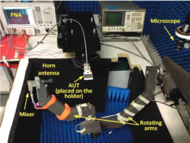
In this work we have used quasi 3-dimensional measurement system [Titz2012] for characterizing the radiation properties of the developed antenna prototypes.The measurement system has an accuracy of ±0.8 dB at 60 GHz. The measurement system is presented in Figure 2.3 and it allows measuring the reflection coefficient of the antenna under test (AUT) and also the realized gain. The GSG-probe is used to feed the AUT, which is placed on a foam holder. The relative permittivity of the holder is close to 1 (ߝ = 1.01), which ensures that the radiation pattern under the antenna can also be measured. At the receiver side the harmonic mixer connected to the horn antenna is used. In order to measure the radiation pattern over the sphere two rotating arms are used. The measurements can be performed over 74% of the sphere. The only part where GSG-probe feeding cables are located, can not be measured. However, this part can be extracted from the simulations. The distance between the receiving horn antenna and AUT is 20 cm. The calibration procedure of the measurement system is described in [Ranvier2009]. The realized gain values can be computed after the measurements. The detailed description of the measurement system and measurement technique can be found in [Titz2012].
27
2.3. Reconfigurable antennas
The growing interest in flexible electronic devices requires stretchable and conformal antennas. The usage of standard metals such as gold or copper limits the development of versatile electronics. Elastic dielectric materials together with liquid metals enable bending and stretching of the developed antenna structure. Antenna structures with the use of liquid metals have been actively investigated in the last years. Usage of liquid metals such as mercury or gallium in the antenna structures has been studied in [Fayad2006]. One of the main advantages of these structures is their reconfigurability. The antenna can have any kind of shape and it can be changed using micro pumps in the structure [So2009, Dickey2013, Erdil2013]. This approach can be used to reconfigure the shape of the antenna and, consequently, control the radiation properties of the antenna. Beam steering can also be implemented by the usage of mechanically tunable antennas in a conformal installation. A cavity milled in the substrate defines the antenna shape. Injecting the liquid metal into one or more cavities forms the antenna configuration. These antennas can be dynamically adapted to the changes in the communication channel or in the system requirements.
Another interesting concept in reconfigurable antennas is the use of conformal antennas and arrays. According to the IEEE Standard Definition of Terms for Antennas: “conformal antenna is an antenna (an array) that conforms to a surface whose shape is determined by considerations other than electromagnetic; for example aerodynamic or hydrodynamic,” [IEEE1993]. First investigations on conformal antenna arrays were done in 1930s [Chireix1936], where dipole elements formed an omnidirectional circular array. Also, a ring array of an infinite number of tangential dipoles, which can be azimuthally omnidirectional, was investigated in [Knudsen1953]. During the early years of World War II, a type of circularly disposed antenna array was developed, which received the name Wullenweber array [Joseffson2006]. Wullenweber technology was developed by the German navy communication research command for radio direction finding. During the Cold War similar systems were developed in different countries. Later, conformal microstrip antennas and microstrip antenna phased arrays providing omnidirectional coverage were studied [Munson1974]. Conformal antenna arrays can be placed on the several surfaces of an object [Vasylchenko2011] or on a continuous supporting structure [Liu2008, Cheng2013]. The azimuth coverage of antennas on continuous surfaces depends on the supporting object geometry [II]. If several antenna arrays are realized on the same printed circuit board (PCB) in a conformal installation with PIN-diodes, such an antenna structure can be used for beam steering or beam switching.
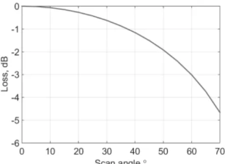
In the conventional planar antenna arrays, the beam can be steered in the range of maximum of ±70˚ without significant degradation of performance [Mailloux2005, Josefsson2006]. The scan loss in an ideal case is equal to
ሺߠ௦ሻ, where ߠ௦ is the scan angle, but in practice it is
28
where the exponent α may vary from 1 to 2 due to mutual coupling of array elements, impedance mismatch, resistive losses, etc. [Mailloux2005]. Figure 2.4 presents the scan loss dependance versus scanning angle, assuming that α = 1. For the ideal case, the antenna gain decreases for about 4.7 dB for the 70˚ scan angle. At the same time, conformal antenna arrays can provide wider scanning angles with the same performance (without significant gain reduction), since the projection of the effective antenna area is larger.
Figure 2.4. Scan loss versus scanning angle (mismatch losses are not taken into account).
2.4.
Contributions
of the thesis
2.4.1. Microfluidic antenna array
In [I], liquid metal patch antenna and reconfigurable antenna array operating at 5.8 GHz were developed and measured. Reconfigurability is achieved using liquid metal alloy which fills milled channels in the substrate of the antenna structure. Two antenna structures were designed using 3D full-wave electromagnetic fields simulator Ansoft HFSSTM: a single patch antenna and a patch antenna array. The array is presented in Figure 2.5 and it is composed of 3 patch elements. First, the 2 mm deep channels for the liquid metal were milled in a 3.25 mm thick Rogers 5880 substrate. Next, the SMA connector was attached. The structure was covered with a thin film of polyethylene terephthalate (PET) material to prevent the liquid metal of going out from the structure. Then, gallium (Ga) alloy was injected into the milled channels.
The next step of the work was to perform radiation pattern measurements. The cylindrical measurement system in All-Russian Scientific Research Institute, Saint Petersburg, was used to measure the radiation performance of the developed antenna structures. Three cases have been simulated and measured: a single patch antenna, feeding one central patch antenna in the antenna array and feeding all three patches in the antenna array. Example of the measured radiation patterns can be seen in Figure 2.6. The measurements were not performed in an anechoic chamber environment. One of the appropriate techniques to compensate for reflections is to use an antenna pattern comparison technique (APC) [Appel-Hansen1973]. This technique was used to compensate the reflections for the central patch in the antenna array (Figure 2.6a).
29
(a)
(b)
Figure 2.5. (a) Simulation model and (b) manufactured patch antenna array, from [I].
(a) (b)
Figure 2.6. Normalized radiation pattern cuts, from [I] (a) feeding one central patch antenna in the array and (b) feeding all three patches in the antenna array.
In [I], the concept of reconfigurable antenna arrays using liquid metal alloy as the patch and strip material was studied. If micro-pumps, which can force the liquid metal to fill desired milled channels, are integrated into this antenna structure, the shape of the radiation element can be changed. The disadvantage of such a structure is low speed of changing the states. However, using properties of liquid metals can help to avoid the main disadvantage of mechanically-actuated reconfigurable antennas, for example, mechanical failures. Another advantage is that antenna arrays with liquid metal as a conductor on a flexible substrate can be deformable and mechanically tunable.
2.4.2. Conformal antenna arrays
Conformal antennas can be used in Wireless Local Area Networks to achieve high data rate communication. Microstrip antenna arrays are the most suitable antennas in conformal installations because of their low profile structure,
30
simple geometry and relatively inexpensive manufacturing. In [II], the conformal 4x4 patch antenna array has been developed for the frequency of 58.8 GHz. The optimized array pattern is placed on Taconic TLY-5 material substrate (εr = 2.2 and tanδ = 0.0009 @ 10 GHz) with the thickness of 0.127
mm. The overall antenna size is 25x20 mm2. The antenna array has been designed for short range communications, such as high definition video transmission in indoor environments. Publication [II] includes the performance measurement results for an antenna array placed on supporting structures with different radii (Figures 2.7, 2.8).
X Y Z 20 mm 25 mm 1.65 mm 1.7 mm 0.12 mm width 0.3 mm width 1.63 mm 1.0925 mm 3.735 mm 3.28 mm 1.64 mm (a) (b)
Figure 2.7. (a) Schematic view of the studied cases and (b) antenna array structure from [II].
(a) (b)
Figure 2.8. Measured total realized gain depending on the curvature radii in (a) XZ-plane and (b) YZ-plane, from [II].
Manufactured antenna prototypes were measured in La Turbie, France. The measurement system presented in [Titz2012] allows measuring fields on quasi-three dimensional sphere over the AUT. Realized gain values were measured versus frequency. In a planar case, the antenna array has a measured gain of 17.2 dB and it decreases to 11.4 dB if the antenna is placed on a convex supporting structure with the radius of 6 mm. Simultaneously, the HPBW of the antenna is enlarged up to 4 times, from 20˚ to 79˚. It was shown that it was possible to obtain a wide azimuth coverage with the decreasing radii of the supporting cylinder. If several antennas are
arranged on the cylinder surface, omni-directional coverage can be obtained with high gain values.
In [III], a beam switching antenna array is presented. Radiation properties for planar and conformal cases were studied. Such an antenna array can be integrated into smart watches for short distance high data rate communications. In particular, three 4x4 patch antenna arrays were designed
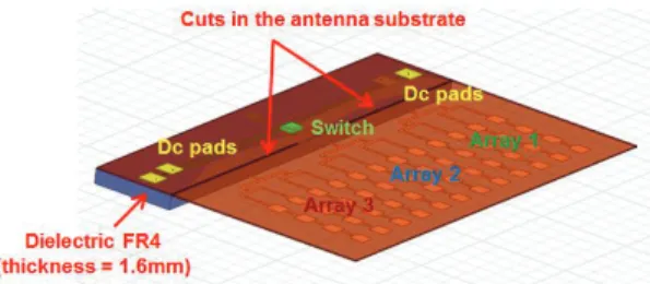
31 using a switching network. Each antenna array consists of 4 parallel connected series-fed linear arrays of 4 microstrip patches. The antenna array is optimized to operate at 59.9 GHz and the overall antenna size is 31x46.4 mm2. The antenna consists of two metallic layers separated by a 0.127 mm thick Rogers RT/Duroid 5880 substrate with relative permittivity of 2.2 and the dielectric loss tangent of 0.0009 (@ 10 GHz). The top layer consist of 3 antenna arrays, DC pads for biasing the switch, and the switch mounting area. On the bottom layer there is a ground plane. To avoid using a multilayer structure for simplifying the manufacturing process, the biasing lines for the switch were also placed on the bottom layer, where the ground plane is partly etched. Blind via holes were drilled from the bottom to the top layer. The antenna array structure is presented in Figure 2.9. A single pole three throw (SP3T) switch was attached to the top layer of the PCB through copper pillar attachment. The feeding part of the antenna is designed for the GSG-probe.
Figure 2.9. 3D view of the antenna structure.
Since the substrate is very thin and flexible, which can lead to breaking down the contacts between the switch and the PCB, FR-4 dielectric material layer was glued to the bottom layer of the antenna. One more reason is that the probing part of the antenna should be planar so that the antenna can be fed by a GSG-probe. For the conformal installation the antenna is placed on a cylinder, while the probing part remains planar. After antenna feeding pads, there is a transition to a microstrip and then back to a coplanar waveguide (CPW) for switch attachment (Figure 2.10a). It was necessary to make a CPW-microstrip-CPW transition, because of the dimensions between the switch pads, which did not allow to design a full CPW line from the probe to the switch. The transition was optimized in HFSSTM and simulated S-parameters are presented in Figure 2.10b. S11 and S22 are below -12 dB level over the frequency range from 57 to 63 GHz.
The losses in the switch were verified through indirect measurements for the planar antenna structure. The antenna structure without the switch was probed and the measured realized gain values were compared with the case when the antenna had a switch. The difference between these two measurements was 5.5 dB and could be caused by the mismatch in the switch connection and also insertion loss of the switch, the nominal value of which is 2.3 dB.
The realized gain values were measured for all three antennas in the planar case. Maximum values are 11.2 dBi for the first antenna array, 11.1 dBi for the second antenna array and 10.1 dBi for the third antenna array. Next, the
32
antenna was placed on a cylinder with the radius of 20 mm (Figure 2.11). Unfortunately, the bending of the antenna also affected the switch. Therefore, the radiation pattern of the central antenna array in a conformal installation could not be measured. The switch did not block the signal to the central antenna array and the feeding microstrip line for that antenna array was cut. Furthermore, the loss of the switch towards antenna 3 increased about 5 dB. The realized gain patterns of the side antenna arrays were measured and the results are presented in Figure 2.12. As can be seen, the scanning angles of the antenna are +34˚ and -32˚.
CPW- Microstrip-CPW transition T-junction power divider SP3T Switch
GSG pad for the probe
(a) (b)
Figure 2.10. (a) Microphotograph of the switch-mounted area, (b) simulated S-parameters of the CPW-microstrip-CPW transition.
(a) (b)
Figure 2.11. Photographs of the developed antenna array from [III] (a) Planar antenna array, (b) Convex antenna array bent on the cylinder with R=20 mm.
Figure 2.12. Measured normalized realized gain antenna radiation patterns, from [III].
The author has authored and co-authored also other related publications [Semkin2013a, Semkin2013b, Viikari2015, Ala-Laurinaho2015, Khairkar2016].
33
3. Radio wave propagation at mm-wave
frequencies
Electromagnetic waves were described by J. C. Maxwell in the classical field theory [Maxwell1865] and, later, in 1880’s they were discovered by Hertz, who was able to create an electromagnetic wave at about 50 MHz and to detect it [Hertz1887]. In 1890’s researchers from different countries investigated the possibility to transmit information via radio waves. In 1895 A. Popov and G. Marconi presented their apparatuses which were able to transmit a radio signal. During the next year Marconi performed necessary experiments and in 1896 he applied for a patent. In 1901 Marconi succeeded in the first transatlantic radio transmission. In 1897 J. C. Bose presented his investigations of electromagnetic waves at cm- and mm- wavelengths [Emerson1998]. However, the mm-wave technology remained mainly unexplored until the middle of the 20th century. Only since 1960’s mm-wave frequencies have been used by radio astronomers and by the military forces. In 1980’s the development of millimeter wave integrated circuits created an opportunity to use mm-wave devices in the commercial applications. In 1990’s automotive collision avoidance radar operating at 77 GHz was introduced. From that time mm-wave frequencies came to civil applications.
Nowadays, since the mobile traffic grows exponentially, the usage of mm-waves for data transmission can be used to improve the overall system capacity. Millimeter wave frequencies generally correspond to the radio spectrum from 30 GHz to 300 GHz, with the wavelength between ten and one millimeter. Compared to the signals at low frequencies which propagate for long distances and also through different objects, millimeter wave signals can propagate for only relatively short distances due to atmospheric attenuation and do not penetrate most solid materials. The atmospheric attenuation at these frequencies can be high. Millimeter waves are absorbed by the gases in the atmosphere, such as oxygen, water vapor, and others [FCC1997, Huang2011]. As can be seen in Figure 3.1, the attenuation at 60 GHz is more than 15 dB/km. However, mm-wave frequencies can provide wider spectrum and allow implementation of links in areas with a high number of users [FCC1997].
34
Figure 3.1. Atmospheric attenuation at mm-wave frequencies (at sea level, 20˚C temperature, 7.5 g/m3 of water content). Reproduced from [FCC1997].
The use of mm-wave frequencies for wireless communications has been supported by the standardization activities. The unlicensed frequency range from 57 to 66 GHz provides growing interest for wireless multi-gigabit communications for indoor environments [IEEE802.15.3c2009, IEEE802.11ad2012]. The frequency ranges from 71-76 GHz and 81-86 GHz (so called E-band) are used for fixed point-to-point radio communications [FCC2005, ETSI2006].
3.1. Ray-optical wave propagation
Electromagnetic theory development was possible due to the appearance of Maxwell’s equations in 1864 [Maxwell1865]. Later, Sommerfeld [1911] linked these equations to the Geometrical Optics (GO) and this work was extended by Luneberg [1944] and Kline [1951], who showed that GO can be presented as an asymptotic solution of Maxwell’s equations. The fields in GO are considered to travel along rays and can be derived geometrically. The GO can be used under the following assumptions [Hall1996]:
x all objects are large relatively to the wavelength;
x the surface is smooth on the wavelength scale;
x curvature radii of obstacles is large in wavelengths;
x the source and receiving points are separated by a large distance in wavelengths;
x the distance between the nearest scatterers is large in wavelengths.
35 In the GO approximation, the energy is carried between two points in an isotropic medium using the conservation of energy flux in a tube of rays. A ray tube is a tube the lateral surface of which is formed by a set of rays, and the bases are two wave front sections (Figure 3.2). In the ray tube the energy flux remains constant and the power density (or intensity) is inversely proportional to the cross-section of the ray tube
ܷ݀ܣൌ ܷ݀ܣ, (3.1)
where ܷ, ܷ are the radiation power densities and ݀ܣ, ݀ܣ are the cross section areas of the tube separated by distance s. Therefore, the power carried by a ray attenuates even in lossless media due to the enlarging of the ray tube cross-section.
Figure 3.3. Astigmatic tube of rays.
It is necessary to define an astigmatic tube of rays, which is a more general configuration of ray tubes, where the rays in the tube are perpendicular to the wavefront and not focused at one point, but pass through two lines called caustics. For an astigmatic tube of rays, presented in Fig. 3.3, the complex electric field amplitude, including phase and polarization, can be found as [Saez de Adana2011]
ܧሬԦሺݏሻ ൌ ܧሺͲሻට ఘభఘమ
ሺఘభା௦ሻሺఘమା௦ሻ݁
ିఉ௦, (3.2)
where ܧሺͲሻ is the electric field at the reference point, ߚ ൌଶగఒ is the propagation constant in free space, ߩଵ and ߩଶ are the curvature radii of the wave front at the reference point. The GO field in caustics is infinite because an infinite number of rays pass through them. There are three possible cases. First, if the two caustics deteriorate into a single point, then the wave front becomes spherical. Second, if one of the two caustics is formed at an infinite distance the wave front is cylindrical. Third, if both caustics are formed at an infinite distance then there is a plane wave.
As it is mentioned above, there is a significant limitation for the GO, when applied to radio-frequency problems; it is not possible to define the field in the shadow areas and at the shadow boundaries. The solution was proposed by
36
Keller [1962], who introduced diffracted rays, which allowed predicting the high-frequency field on the edges of objects. From that time an extension of GO, which was called Geometrical Theory of Diffraction (GTD), appeared. Later, the theory was further developed, because the original GTD proposed by Keller contained some problems, such as infinite diffracted field outside the shadow and reflection boundaries. This lead to the appearance of the Uniform Theory of Diffraction [Kouyoumjian1974].
3.2. Propagation mechanisms
Radio waves propagate in space according to several interaction mechanisms with the surrounding objects: free space propagation, reflection, transmission, diffraction, and scattering, as shown in Figure 3.4. Human blockage can also have a high impact on the radio wave propagation at mm-wave frequencies.
Figure 3.4. Possible propagation mechanisms by rays facing the building wall. Adopted from [Degli-Esposti2014].
3.2.1. Free-space propagation
The waves propagating from the transmitter (Tx) to the receiver (Rx) without any obstacles, and when there is only a line-of-sight connection, can be described by the free space propagation model [Friis1946]. The frequency and distance dependence of the loss between two antennas in free space can be expressed by Friis’ law (2.5). The free space loss factor is defined as in (2.6).
3.2.2. Ray reflection and transmission
Electromagnetic waves are often reflected at one or more objects before arriving at the receiver. Reflection is one of the dominant propagation mechanisms. Usually, if the interaction objects have smooth surfaces and are larger than the wavelength, only transmission and specular reflection take place (Fig. 3.5). When a ray impinges on a plane surface, the incident field is split into an incident, a reflected, and a transmitted one. The incident ray trajectory is modified according to Snell’s law, where the angle of incidence (ߠ) is equal to the reflection angle (ߠ).
37
(a) (b)
Figure 3.5. Reflection and transmission at the interface between two media (a) parallel polarization, (b) perpendicular polarization.
The field amplitude and phase changes at the interaction point can be calculated according to proper Fresnel’s reflection coefficients, which can be found, e.g., in [Mittra2014].
3.2.3. Scattering from rough surfaces
For a smooth surface, the total energy of a ray is reflected in the specular direction, as it was shown in the previous section. However, in the real cases, some portion of energy is scattered in all directions due to the roughness of the surface. This mechanism is very relevant at mm-wave frequencies, since roughness of a surface can be comparable with the wavelength. Scattering effect can have a large impact on the ray tracing simulations in urban environments since the surfaces of buildings are not ideal. There are two main theories which describe the scattering mechanism: Kirchhoff’s theory and the perturbation theory. For the surface roughness estimation Kirchhoff’s theory requires that the probability density function of surface height is known. It assumes that the height variations are small enough not to influence the nearest scattering points. If this condition is fulfilled, the specular reflected ray will be attenuated by a certain value. The decrease of the power can be described by the effective reflection coefficient [Molisch2011]:
ߩ୰୭୳୦ൌ ߩୱ୫୭୭୲୦݁ିଶሺఉఙୱ୧୬ఏሻమ (3.3) where ߩ୰୭୳୦ is the effective reflection coefficient, ߩୱ୫୭୭୲୦ is the reflection
coefficient from the smooth surface, ߚ is the propagation constant, ߪ is the standard deviation of the height distribution, and ߠ is the angle of incidence. However, the Kirchhoff theory is limited and cannot be used for small angles of incidence, since the height variation in a surface roughness becomes significant.
The perturbation theory, in addition to the probability density function, utilizes the spatial correlation function. In this case it is not probable that a shadowing region will appear. The effect of the surface roughness on the
38
specularly reflected ray can be described by a complex dielectric constant, which influences the reflection coefficient. More detailed description and formulas for the complex dielectric constant can be found in [Vaughan2003].
Different statistical scattering models were proposed by Didascalou [2003], Kloch [1997], Degli-Esposti [1999]. However, it is necessary to validate proposed scattering models by measurements. In [Degli-Esposti2007], scattering from different types of walls was measured and modeled at 1296 MHz, and in [Al-Nuaimi1994], a measurement campaign was conducted at 11.2 GHz to estimate the scattering effects from real buildings. Langen, et. al. [1994] performed amplitude measurements of a signal to define the scattering properties at 60 GHz. In [V], a wideband channel measurement system was used to define the multipath components from the LOS connection and the scattering patterns were measured from different observation angles at E-band. In contrast with Langen’s [1994] work, not only amplitude measurements have been performed, but also phase information has been acquired.
3.2.4. Diffraction and human blockage models
The main limitation of the GO is that only direct and reflected fields can be predicted. In order to predict the electromagnetic field in the shadow regions, the extension of the GO, called geometrical theory of diffraction (GTD), should be used, which takes into account diffraction effects. According to the GTD, the incident ray causes an infinite number of diffracted rays, which are placed on Keller’s cone, Figure 3.6. However, the GTD exhibits singularities at shadow boundaries and caustics. A uniform asymptotic method, i.e. uniform theory of diffraction (UTD), was proposed by Kouyoumjian [1974] to calculate the fields in all regions. The UTD includes Fresnel integrals in the diffraction coefficient and gives an accurate result close to the boundaries [Mittra2014].
39 Figure 3.7. Top view of the MKE diffraction model, rays 1 and 3 represent diffraction over the
human body, and ray 2 represents diffraction over the head.
Different diffraction models of human bodies have been studied [Ghaddar2007, Gustafson2012]. In this thesis, we have used multiple knife edge (MKE) diffraction model for human blockage developed by Jacob [2011, 2013] in the ray tracing simulations [IV]. This human blockage model was extended from a double vertical knife-edge diffraction model developed by Kunisch [2008]. The extended model includes an additional plane which is parallel to the body axis. This improvement is necessary, since in the original model the diffracted rays are not taken into account if the person movement is parallel to the propagating ray. In addition, the MKE diffraction model takes into account diffraction over the human head (Figure 3.7).
3.3. Characterization of radio wave propagation at mm-wave
frequencies
3.3.1. Ray tracing techniques
Ray-optical modeling algorithms can be divided into two categories: the image method (IM) and the shooting-and-bouncing ray (SBR) method [Mittra2014]. Usually, algorithms based on IM are called Ray Tracing (RT) and algorithms based on SBR method are called Ray Launching (RL). Ray Tracing is a technique for generating an image of a source by calculating the paths taken by rays of light entering the observer’s eye at different angles. This technique is widely used not only in computer graphics, but also in radio wave propagation studies [Döttling1997a, Degli-Esposti2014, Fugen2007, Fuschini2008, Rautiainen2007]. If the wavelength is smaller than the surrounding objects, electromagnetic waves can be approximated by rays for which the geometrical optics rules are valid. Deterministic propagation models based on Geometrical Optics and Uniform Theory of Diffraction can provide reliable estimations of radio wave propagation in a specific environment [McKown1991].
Another method is the shooting-and-bouncing ray (SBR) method, or so-called ray launching, which also belongs to the group of deterministic models and can be used for radio wave propagation modelling [Kipp2004, Sato2005, Rose2014]. In the SBR method the rays are launched from a transmitter towards all directions in order to cover the angular space around the source. When a ray hits an object, it is split into transmitted and reflected ones. The relationship between the angles of incidence and refraction is calculated by Snell’s law. In comparison, the IM cannot use Snell’s law because the Tx and
40
Rx positions are fixed. The diffracted field is calculated on the edges and vertexes of the objects. The SBR is a direct method and it does not depend on the observation point position of the Rx antenna. The rays that reach the observation point contribute to the total electromagnetic field [Mittra2014]. Ray Launching method can be more suitable for planning the wireless networks since it is computationally more efficient than Ray Tracing [Gschwendtner1995]. The SBR method is preferable for the use in complex environments, since the IM can be computationally inefficient when there are higher order reflections and diffractions, especially in 3D models.
There are also other ray tracing techniques, developed from the IM/SBR method or their combination [Liang1997, Iskander2001, Mohtashami2010, Liu2012], however, they are not in the scope of this thesis.
3.3.2. Photogrammetry and its applicability for ray launching simulations
Since wireless radio links can be strongly influenced by propagation effects, it is necessary to know the detailed geometry of the environment. This is especially true at mm-wave frequencies when all the details of the object geometry can influence the propagation characteristics. A ray tracing software requires as input the object geometry. Considering urban scenarios with a lot of small objects like details of the facades of the buildings, traffic lights/signs etc., a detailed geometry description of the environment is needed in order to get reliable results for radio wave propagation prediction.
Photogrammetry
![Figure 2.1. Mobile traffic forecast [Cisco2016].](https://thumb-us.123doks.com/thumbv2/123dok_us/508308.2559983/22.748.290.542.716.903/figure-mobile-traffic-forecast-cisco.webp)
![Table 1. Technologies for the implementation of reconfigurable reflect arrays and reconfigurable array lens (“-”, “0”, and “/” symbols refer to good, neutral, and poor, respectively), based on [Hum2014]](https://thumb-us.123doks.com/thumbv2/123dok_us/508308.2559983/24.748.223.617.157.576/technologies-implementation-reconfigurable-reflect-reconfigurable-symbols-neutral-respectively.webp)
![Figure 2.6. Normalized radiation pattern cuts, from [I] (a) feeding one central patch antenna in the array and (b) feeding all three patches in the antenna array.](https://thumb-us.123doks.com/thumbv2/123dok_us/508308.2559983/30.748.191.649.436.625/figure-normalized-radiation-pattern-feeding-central-antenna-feeding.webp)
![Figure 2.8. Measured total realized gain depending on the curvature radii in (a) XZ-plane and (b) YZ-plane, from [II]](https://thumb-us.123doks.com/thumbv2/123dok_us/508308.2559983/31.748.113.556.259.402/figure-measured-total-realized-depending-curvature-radii-plane.webp)
![Figure 2.11. Photographs of the developed antenna array from [III] (a) Planar antenna array, (b) Convex antenna array bent on the cylinder with R=20 mm.](https://thumb-us.123doks.com/thumbv2/123dok_us/508308.2559983/33.748.158.506.516.660/figure-photographs-developed-antenna-planar-antenna-convex-cylinder.webp)
